clock DODGE CHARGER 2021 Owners Manual
[x] Cancel search | Manufacturer: DODGE, Model Year: 2021, Model line: CHARGER, Model: DODGE CHARGER 2021Pages: 320, PDF Size: 20.61 MB
Page 44 of 320
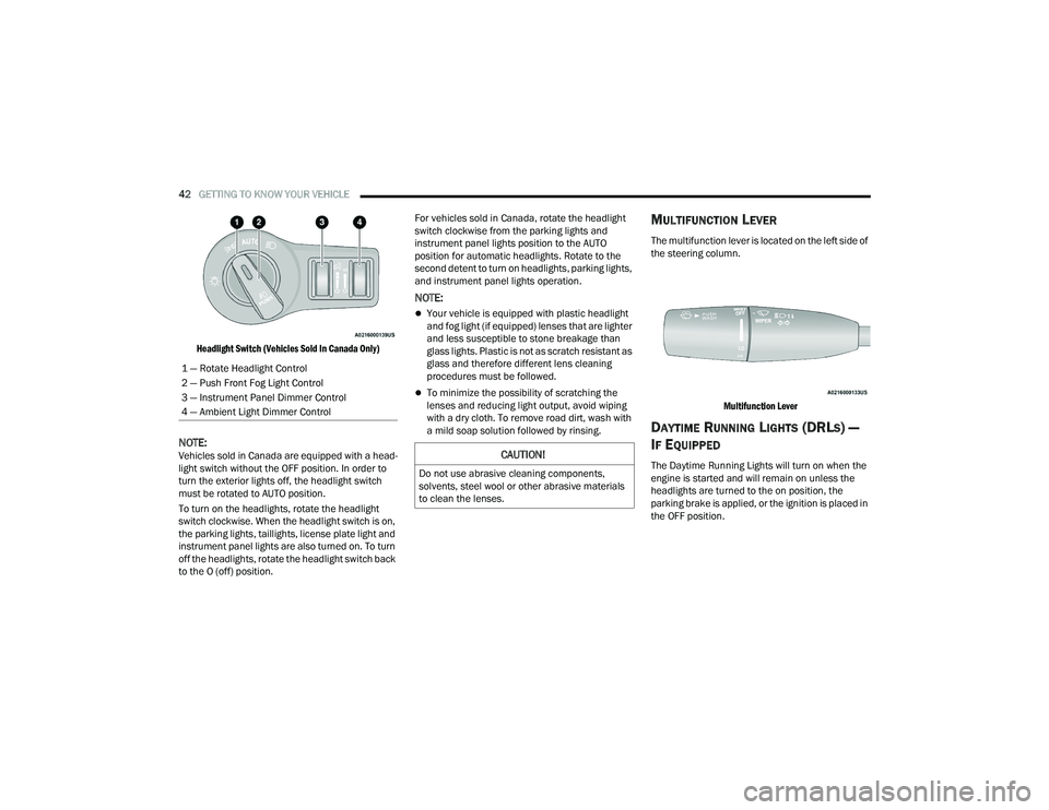
42GETTING TO KNOW YOUR VEHICLE
Headlight Switch (Vehicles Sold In Canada Only)
NOTE:Vehicles sold in Canada are equipped with a head -
light switch without the OFF position. In order to
turn the exterior lights off, the headlight switch
must be rotated to AUTO position.
To turn on the headlights, rotate the headlight
switch clockwise. When the headlight switch is on,
the parking lights, taillights, license plate light and
instrument panel lights are also turned on. To turn
off the headlights, rotate the headlight switch back
to the O (off) position. For vehicles sold in Canada, rotate the headlight
switch clockwise from the parking lights and
instrument panel lights position to the AUTO
position for automatic headlights. Rotate to the
second detent to turn on headlights, parking lights,
and instrument panel lights operation.
NOTE:
Your vehicle is equipped with plastic headlight
and fog light (if equipped) lenses that are lighter
and less susceptible to stone breakage than
glass lights. Plastic is not as scratch resistant as
glass and therefore different lens cleaning
procedures must be followed.
To minimize the possibility of scratching the
lenses and reducing light output, avoid wiping
with a dry cloth. To remove road dirt, wash with
a mild soap solution followed by rinsing.
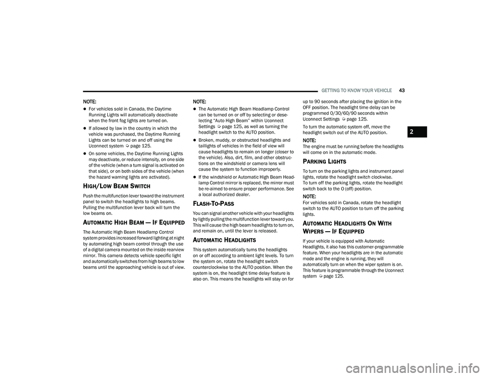
MULTIFUNCTION LEVER
The multifunction lever is located on the left side of
the steering column.
Multifunction Lever
DAYTIME RUNNING LIGHTS (DRLS) —
I
F EQUIPPED
The Daytime Running Lights will turn on when the
engine is started and will remain on unless the
headlights are turned to the on position, the
parking brake is applied, or the ignition is placed in
the OFF position.
1 — Rotate Headlight Control
2 — Push Front Fog Light Control
3 — Instrument Panel Dimmer Control
4 — Ambient Light Dimmer ControlCAUTION!
Do not use abrasive cleaning components,
solvents, steel wool or other abrasive materials
to clean the lenses.
21_LD_OM_EN_USC_t.book Page 42
Page 45 of 320
GETTING TO KNOW YOUR VEHICLE43
NOTE:
For vehicles sold in Canada, the Daytime
Running Lights will automatically deactivate
when the front fog lights are turned on.
If allowed by law in the country in which the
vehicle was purchased, the Daytime Running
Lights can be turned on and off using the
Uconnect system Úpage 125.
On some vehicles, the Daytime Running Lights
may deactivate, or reduce intensity, on one side
of the vehicle (when a turn signal is activated on
that side), or on both sides of the vehicle (when
the hazard warning lights are activated).
HIGH/LOW BEAM SWITCH
Push the multifunction lever toward the instrument
panel to switch the headlights to high beams.
Pulling the multifunction lever back will turn the
low beams on.
AUTOMATIC HIGH BEAM — IF EQUIPPED
The Automatic High Beam Headlamp Control
system provides increased forward lighting at night
by automating high beam control through the use
of a digital camera mounted on the inside rearview
mirror. This camera detects vehicle specific light
and automatically switches from high beams to low
beams until the approaching vehicle is out of view.
NOTE:
The Automatic High Beam Headlamp Control
can be turned on or off by selecting or dese -
lecting “Auto High Beam” within Uconnect
Settings Ú page 125, as well as turning the
headlight switch to the AUTO position.
Broken, muddy, or obstructed headlights and
taillights of vehicles in the field of view will
cause headlights to remain on longer (closer to
the vehicle). Also, dirt, film, and other obstruc -
tions on the windshield or camera lens will
cause the system to function improperly.
If the windshield or Automatic High Beam Head -
lamp Control mirror is replaced, the mirror must
be re-aimed to ensure proper performance. See
a local authorized dealer.
FLASH-TO-PASS
You can signal another vehicle with your headlights
by lightly pulling the multifunction lever toward you.
This will cause the high beam headlights to turn on,
and remain on, until the lever is released.
AUTOMATIC HEADLIGHTS
This system automatically turns the headlights
on or off according to ambient light levels. To turn
the system on, rotate the headlight switch
counterclockwise to the AUTO position. When the
system is on, the headlight time delay feature is
also on. This means the headlights will stay on for up to 90 seconds after placing the ignition in the
OFF position. The headlight time delay can be
programmed 0/30/60/90 seconds within
Uconnect Settings Ú
page 125.
To turn the automatic system off, move the
headlight switch out of the AUTO position.
NOTE:The engine must be running before the headlights
will come on in the automatic mode.
PARKING LIGHTS
To turn on the parking lights and instrument panel
lights, rotate the headlight switch clockwise.
To turn off the parking lights, rotate the headlight
switch back to the O (off) position.
NOTE:For vehicles sold in Canada, rotate the headlight
switch to the AUTO position to turn off the parking
lights.
AUTOMATIC HEADLIGHTS ON WITH
W
IPERS — IF EQUIPPED
If your vehicle is equipped with Automatic
Headlights, it also has this customer-programmable
feature. When your headlights are in the automatic
mode and the engine is running, they will
automatically turn on when the wiper system is on.
This feature is programmable through the Uconnect
system
Ú
page 125.
2
21_LD_OM_EN_USC_t.book Page 43
Page 52 of 320
50GETTING TO KNOW YOUR VEHICLE
Driver And Passenger Temperature Up And
Down Buttons
These buttons provide the driver and passenger
with independent temperature control.
Push the red button on the faceplate
or touchscreen or press and slide the
temperature bar towards the red arrow
button on the touchscreen for warmer
temperature settings.
Push the blue button on the faceplate
or touchscreen or press and slide the
temperature bar towards the blue arrow
button on the touchscreen for cooler
temperature settings.
SYNC Button
Press the SYNC button on the
touchscreen to toggle the SYNC feature
on/off. The SYNC indicator illuminates
when SYNC is on. SYNC synchronizes the
passenger temperature setting with the driver
temperature setting. Changing the passenger’s
temperature setting while in SYNC will
automatically exit this feature.
NOTE:The SYNC button is only available on the touch-
screen.
Blower Control
Blower Control regulates the amount of
air forced through the Climate Control
system. There are seven blower speeds
available. Adjusting the blower will cause
automatic mode to switch to manual operation.
The speeds can be selected using either the
blower control knob on the faceplate or the
buttons on the touchscreen.
Faceplate
The blower speed increases as you turn the blower
control knob clockwise from the lowest blower
setting. The blower speed decreases as you turn
the blower control knob counterclockwise.
Touchscreen
Use the small blower icon to reduce the blower
setting and the large blower icon to increase the
blower setting. Blower can also be selected by
pressing the blower bar area between the icons.
Mode Control
Select Mode by pressing one of the Mode
buttons on the touchscreen to change
the airflow distribution mode. The airflow
distribution mode can be adjusted so air
comes from the instrument panel outlets, floor
outlets, defrost outlets, and demist outlets.
Panel Mode
Air comes from the outlets in the
instrument panel. Each of these outlets
can be individually adjusted to direct the
flow of air. The air vanes of the center
outlets and outboard outlets can be moved up and
down or side to side to regulate airflow direction.
There is a shut off wheel located below the air
vanes to shut off or adjust the amount of airflow
from these outlets.
Bi-Level Mode
Air comes from the instrument panel
outlets and floor outlets. A slight amount
of air is directed through the defrost and
side window demister outlets.
NOTE:Bi-Level mode is designed under comfort condi -
tions to provide cooler air out of the panel outlets
and warmer air from the floor outlets.
Floor Mode
Air comes from the floor outlets. A slight
amount of air is directed through the defrost
and side window demister outlets.
21_LD_OM_EN_USC_t.book Page 50
Page 54 of 320
52GETTING TO KNOW YOUR VEHICLE
Rear Defrost Button
Press and release the Rear Defrost
button on the touchscreen, or push and
release the button on the faceplate, to
turn on the rear window defroster and the
heated outside mirrors (if equipped). The Rear
Defrost indicator illuminates when the rear window
defroster is on. The rear window defroster
automatically turns off after 10 minutes.
Driver And Passenger Temperature
Control Buttons
These buttons provide the driver and passenger
with independent temperature control.
Push the red button on the faceplate
or touchscreen or press and slide the
temperature bar towards the red arrow
button on the touchscreen for warmer
temperature settings.
Push the blue button on the faceplate
or touchscreen or press and slide the
temperature bar towards the blue arrow
button on the touchscreen for cooler
temperature settings.
SYNC Button
Press the SYNC button on the
touchscreen to toggle the SYNC feature
on/off. The SYNC indicator illuminates
when SYNC is on. SYNC synchronizes the
passenger temperature setting with the driver
temperature setting. Changing the passenger’s
temperature setting while in SYNC will
automatically exit this feature.
NOTE:The SYNC button is only available on the touch-
screen.
Blower Control
Blower Control regulates the amount of
air forced through the Climate Control
system. There are seven blower speeds
available. Adjusting the blower will cause
automatic mode to switch to manual operation.
The speeds can be selected using either the
blower control knob on the faceplate or the
buttons on the touchscreen.
Faceplate
The blower speed increases as you turn the blower
control knob clockwise from the lowest blower
setting. The blower speed decreases as you turn
the blower control knob counterclockwise.
Touchscreen
Use the small blower icon to reduce the blower
setting and the large blower icon to increase the
blower setting. Blower can also be selected by
pressing the blower bar area between the icons.
Mode Control
Select Mode by pressing one of the Mode
buttons on the touchscreen to change
the airflow distribution mode. The airflow
distribution mode can be adjusted so air
comes from the instrument panel outlets, floor
outlets, defrost outlets, and demist outlets.
CAUTION!
Failure to follow these cautions can cause
damage to the heating elements:
Use care when washing the inside of the rear
window. Do not use abrasive window cleaners
on the interior surface of the window. Use a
soft cloth and a mild washing solution, wiping
parallel to the heating elements. Labels can
be peeled off after soaking with warm water.
Do not use scrapers, sharp instruments, or
abrasive window cleaners on the interior
surface of the window.
Keep all objects a safe distance from the
window.
21_LD_OM_EN_USC_t.book Page 52
Page 115 of 320
STARTING AND OPERATING113
NOTE:
If snow, ice, mud, or any foreign substance builds up on
the camera lens, clean the lens, rinse with water, and
dry with a soft cloth. Do not cover the lens.
REFUELING THE VEHICLE
1. Put the vehicle in PARK and switch the
ignition off.
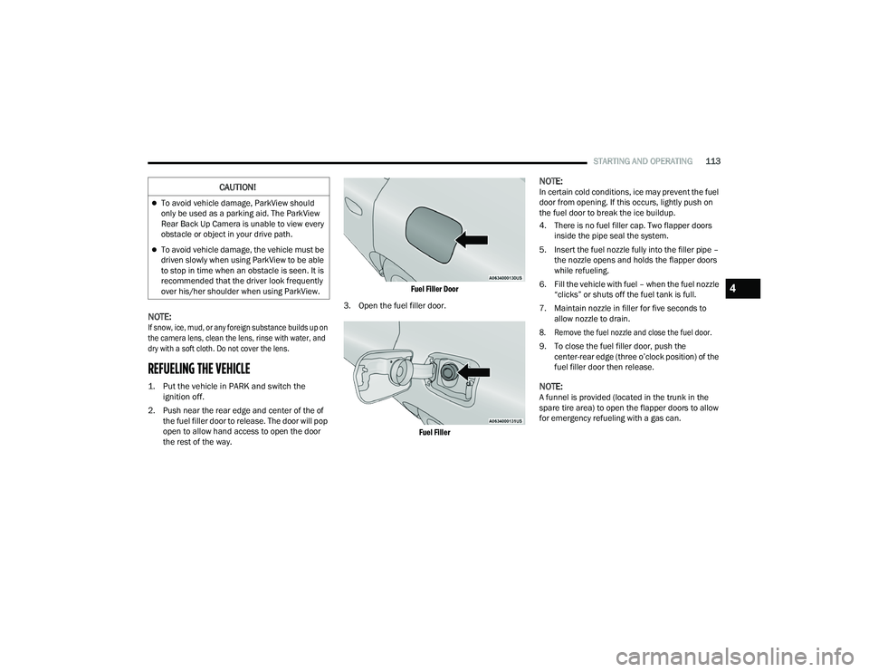
2. Push near the rear edge and center of the of the fuel filler door to release. The door will pop
open to allow hand access to open the door
the rest of the way.
Fuel Filler Door
3. Open the fuel filler door.
Fuel Filler
NOTE:In certain cold conditions, ice may prevent the fuel
door from opening. If this occurs, lightly push on
the fuel door to break the ice buildup.
4. There is no fuel filler cap. Two flapper doors inside the pipe seal the system.
5. Insert the fuel nozzle fully into the filler pipe – the nozzle opens and holds the flapper doors
while refueling.
6. Fill the vehicle with fuel – when the fuel nozzle “clicks” or shuts off the fuel tank is full.
7. Maintain nozzle in filler for five seconds to allow nozzle to drain.
8. Remove the fuel nozzle and close the fuel door.
9. To close the fuel filler door, push the center-rear edge (three o’clock position) of the
fuel filler door then release.
NOTE:A funnel is provided (located in the trunk in the
spare tire area) to open the flapper doors to allow
for emergency refueling with a gas can.
CAUTION!
To avoid vehicle damage, ParkView should
only be used as a parking aid. The ParkView
Rear Back Up Camera is unable to view every
obstacle or object in your drive path.
To avoid vehicle damage, the vehicle must be
driven slowly when using ParkView to be able
to stop in time when an obstacle is seen. It is
recommended that the driver look frequently
over his/her shoulder when using ParkView.
4
21_LD_OM_EN_USC_t.book Page 113
Page 130 of 320
128MULTIMEDIA
Voice
Clock
When the Voice button is pressed on the touchscreen, the system displays the options related to the vehicle’s Voice Recognition feature.
NOTE:Depending on the vehicle’s options, feature settings may vary.
Setting Name Description
Voice Response LengthThis setting will change the response length for the Voice Recognition system. The “Brief” setting
provides a shortened audio description from the system. The “Detailed” setting provides the full audio description from the system.
Show Command List This setting will allow you to turn the Command List on or off. The “Always” setting will always show the
Command List. The “With Help” setting will show the Command List and provide a brief description of what the command does. The “Never” setting will turn the Command List off.
When the Clock button is pressed on the touchscreen, the system displays the different options related to the vehicle’s internal clock.
NOTE:Depending on the vehicle’s options, feature settings may vary.
Setting Name Description
Sync Time With GPSThis setting will sync the time to the GPS receiver in the system. The system will control the time via
the GPS location.
Time Format This setting will allow you set the time format (AM/PM). Sync Time With GPS must be off for this setting
to be available. The “12 hrs” setting will set the time to a 12-hour format. The “24 hrs” setting will set the time to a 24-hour format.
21_LD_OM_EN_USC_t.book Page 128
Page 143 of 320
MULTIMEDIA141
UCONNECT MODES
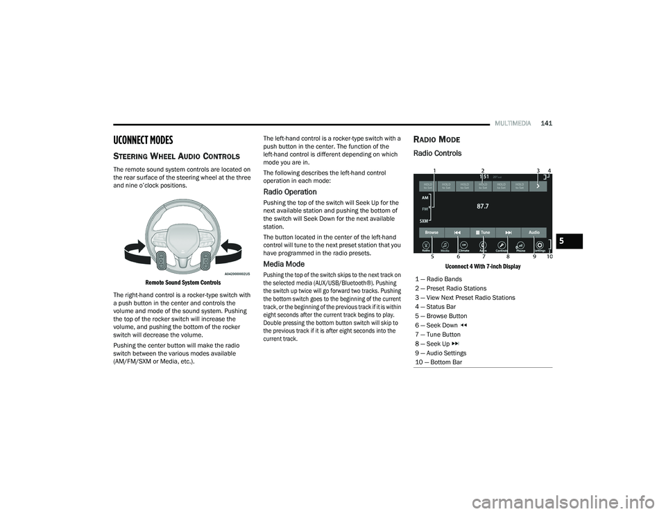
STEERING WHEEL AUDIO CONTROLS
The remote sound system controls are located on
the rear surface of the steering wheel at the three
and nine o’clock positions.
Remote Sound System Controls
The right-hand control is a rocker-type switch with
a push button in the center and controls the
volume and mode of the sound system. Pushing
the top of the rocker switch will increase the
volume, and pushing the bottom of the rocker
switch will decrease the volume.
Pushing the center button will make the radio
switch between the various modes available
(AM/FM/SXM or Media, etc.). The left-hand control is a rocker-type switch with a
push button in the center. The function of the
left-hand control is different depending on which
mode you are in.
The following describes the left-hand control
operation in each mode:
Radio Operation
Pushing the top of the switch will Seek Up for the
next available station and pushing the bottom of
the switch will Seek Down for the next available
station.
The button located in the center of the left-hand
control will tune to the next preset station that you
have programmed in the radio presets.
Media Mode
Pushing the top of the switch skips to the next track on
the selected media (AUX/USB/Bluetooth®). Pushing
the switch up twice will go forward two tracks. Pushing
the bottom switch goes to the beginning of the current
track, or the beginning of the previous track if it is within
eight seconds after the current track begins to play.
Double pressing the bottom button switch will skip to
the previous track if it is after eight seconds into the
current track.
RADIO MODE
Radio Controls
Uconnect 4 With 7-inch Display
1 — Radio Bands
2 — Preset Radio Stations
3 — View Next Preset Radio Stations
4 — Status Bar
5 — Browse Button
6 — Seek Down
7 — Tune Button
8 — Seek Up
9 — Audio Settings
10 — Bottom Bar
5
21_LD_OM_EN_USC_t.book Page 141
Page 144 of 320
142MULTIMEDIA
The radio is equipped with the following modes:
AM
FM
SiriusXM® Satellite Radio (if equipped)
Press the Radio button on the touchscreen to enter
the Radio Mode. The different tuner modes, AM,
FM, and SXM, can then be selected by pressing the
corresponding buttons in Radio Mode.
Volume & On/Off Control
Push the Volume & On/Off control knob to turn on
and off the Uconnect system.
The electronic volume control turns continuously
(360 degrees) in either direction, without stopping.
Turning the Volume & On/Off control knob
clockwise increases the volume, and
counterclockwise decreases it.
When the audio system is turned on, the sound will
be set at the same volume level as last played.
Mute Button
Push the Mute button to mute or unmute the
system. Tune/Scroll Control
Turn the rotary Tune/Scroll control knob clockwise
to increase or counterclockwise to decrease the
radio station frequency. Push the Enter/Browse
button to choose a selection.
Seek
The Seek Up and Down functions are activated
by pressing the double arrow buttons on the
touchscreen to the right and left of the radio station
display or by pushing the left steering wheel audio
control button up or down.
Seek Up and Seek Down
Press and release the Seek Up or Seek Down
button to tune the radio to the next available station
or channel. During a Seek Up/Down function, if the
radio reaches the starting station after passing
through the entire band two times, the radio will stop
at the station where it began.
Fast Seek Up and Fast Seek Down
Press and hold, and then release the Seek Up
or Seek Down button to advance the radio
through the available stations or channels at a
faster rate. The radio stops at the next available
station or channel when the button on the
touchscreen is released.
NOTE:
Pressing and holding either the Seek Up or
Seek Down button will scan the different
frequency bands at a slower rate.
Direct Tune
Press the Tune button located at the bottom of the
radio screen to directly tune to a desired radio
station or channel.
Press the available number button on the
touchscreen to begin selecting a desired station.
Once a number has been entered, any numbers
that are no longer possible (stations that cannot be
reached) will become deactivated/grayed out.
Undo
You can backspace an entry by pressing the
Back button on the touchscreen.
GO
Once the last digit of a station has been entered,
press “Ok”. The Direct Tune screen will close, and
the system will automatically tune to that station.
21_LD_OM_EN_USC_t.book Page 142
Page 229 of 320
IN CASE OF EMERGENCY227
2. Turn on the Hazard Warning Flashers.
3. Apply the parking brake.
4. Place the gear selector into PARK (P).
5. Turn off the ignition.
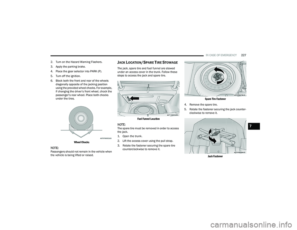
6. Block both the front and rear of the wheels diagonally opposite of the jacking position
using the provided wheel chocks. For example,
if changing the driver’s front wheel, chock the
passenger’s rear wheel. Place both chocks
under the tires.
Wheel Chocks
NOTE:Passengers should not remain in the vehicle when
the vehicle is being lifted or raised.
JACK LOCATION/SPARE TIRE STOWAGE
The jack, spare tire and fuel funnel are stowed
under an access cover in the trunk. Follow these
steps to access the jack and spare tire.
Fuel Funnel Location
NOTE:The spare tire must be removed in order to access
the jack.
1. Open the trunk.
2. Lift the access cover using the pull strap.
3. Rotate the fastener securing the spare tire counterclockwise to remove it.
Spare Tire Fastener
4. Remove the spare tire.
5. Rotate the fastener securing the jack counter -
clockwise to remove it.
Jack Fastener
7
21_LD_OM_EN_USC_t.book Page 227
Page 231 of 320
IN CASE OF EMERGENCY229
1. Remove the spare tire, jack, wheel chocks, and lug wrench.
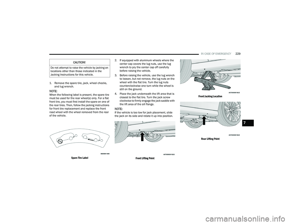
NOTE:When the following label is present, the spare tire
must be used for the rear wheel(s) only. For a flat
front tire, you must first install the spare on one of
the rear tires. Then, follow the jacking instructions
for front tire replacement and replace the front
road wheel with the wheel removed from the rear
of the vehicle.
Spare Tire Label
2. If equipped with aluminum wheels where the
center cap covers the lug nuts, use the lug
wrench to pry the center cap off carefully
before raising the vehicle.
3. Before raising the vehicle, use the lug wrench to loosen, but not remove, the lug nuts on the
wheel with the flat tire. Turn the lug nuts
counterclockwise one turn while the wheel is
still on the ground.
4. Place the jack underneath the lift area that is closest to the flat tire. Turn the jack screw
clockwise to firmly engage the jack saddle with
the lift area of the sill flange.
NOTE:If the vehicle is too low for jack placement, slide
the jack on its side and rotate it up into position.
Front Lifting Point Front Jacking Location
Rear Lifting Point
CAUTION!
Do not attempt to raise the vehicle by jacking on
locations other than those indicated in the
Jacking Instructions for this vehicle.
7
21_LD_OM_EN_USC_t.book Page 229