open hood DODGE CHARGER 2021 Owners Manual
[x] Cancel search | Manufacturer: DODGE, Model Year: 2021, Model line: CHARGER, Model: DODGE CHARGER 2021Pages: 320, PDF Size: 20.61 MB
Page 5 of 320
3
EXTERIOR LIGHTS.................................................. 41 Headlight Switch...............................................41
Multifunction Lever ..........................................42
Daytime Running Lights (DRLs) —
If Equipped........................................................42
High/Low Beam Switch....................................43
Automatic High Beam — If Equipped ..............43
Flash-To-Pass....................................................43
Automatic Headlights ......................................43
Parking Lights ..................................................43
Automatic Headlights On With Wipers — If
Equipped ...........................................................43
Headlight Delay ...............................................44
Lights-On Reminder .........................................44
Fog Lights — If Equipped ..................................44
Turn Signals .....................................................44
Lane Change Assist — If Equipped ..................44
Battery Saver ....................................................45
INTERIOR LIGHTS ................................................. 45
Interior Courtesy Lights ....................................45
WINDSHIELD WIPERS AND WASHERS .............. 47
Windshield Wiper Operation ............................47
Rain Sensing Wipers — If Equipped ................48
CLIMATE CONTROLS ............................................ 48
Automatic Climate Control Descriptions And
Functions .........................................................48
Manual Climate Control Descriptions And
Functions .........................................................51
Automatic Temperature
Control (ATC) ....................................................53 Climate Voice Commands................................53
Operating Tips .................................................54
INTERIOR STORAGE AND EQUIPMENT ............... 55
Storage..............................................................55
USB/AUX Control ..............................................56
Illuminated Cupholders —
If Equipped........................................................56
Power Outlets ...................................................57
WINDOWS ..............................................................58
Power Window Controls ...................................58
Automatic Window Features ...........................59
Reset Auto-Up ..................................................59
Window Lockout Switch ...................................60
Wind Buffeting .................................................60
POWER SUNROOF — IF EQUIPPED ...................... 60
Opening And Closing The Sunroof...................61
Pinch Protect Feature ......................................61
Venting Sunroof................................................61
Sunshade Operation ........................................61
Sunroof Maintenance ......................................61
Ignition Off Operation.......................................61
HOOD .......................................................................62
Opening The Hood ...........................................62
Closing The Hood .............................................62
TRUNK......................................................................63
Opening The Trunk ...........................................63
Closing The Trunk.............................................63
Trunk Safety .....................................................63
Cargo Area Features .......................................64
GETTING TO KNOW YOUR
INSTRUMENT PANEL
INSTRUMENT CLUSTER......................................... 65
Instrument Cluster Descriptions ..................... 67
INSTRUMENT CLUSTER DISPLAY ........................ 67
Location And Controls ..................................... 68
Engine Oil Life Reset ........................................ 69
Performance Shift Indicator
(PSI) — If Equipped ........................................... 69
Instrument Cluster Display Selectable
Menu Items ...................................................... 70
Battery Saver On/Battery Saver Mode
Message — Electrical Load Reduction
Actions — If Equipped ..................................... 73
WARNING LIGHTS AND MESSAGES ................... 74
Red Warning Lights ..........................................74
Yellow Warning Lights ...................................... 77
Yellow Indicator Lights ..................................... 79
Green Indicator Lights ..................................... 80
White Indicator Lights ...................................... 80
Blue Indicator Lights ........................................ 81
ONBOARD DIAGNOSTIC SYSTEM — OBD II ....... 81
Onboard Diagnostic System
(OBD II) Cybersecurity ...................................... 81
EMISSIONS INSPECTION AND MAINTENANCE
PROGRAMS ........................................................... 82
21_LD_OM_EN_USC_t.book Page 3
Page 8 of 320
6
SERVICING AND MAINTENANCE
SCHEDULED SERVICING .................................... 245
3.6L And 5.7L Engines ................................. 245
ENGINE COMPARTMENT .................................... 249
3.6L Engine ................................................... 2495.7L Engine ................................................... 250Checking Oil Level ......................................... 251
Adding Washer Fluid ..................................... 251
Maintenance-Free Battery ........................... 252
Pressure Washing ......................................... 252
VEHICLE MAINTENANCE ..................................... 253
Engine Oil ....................................................... 253
Engine Oil Filter ............................................. 254
Engine Air Cleaner Filter .............................. 254Air Conditioner Maintenance ....................... 254
Accessory Drive Belt Inspection ................... 256
Body Lubrication............................................ 256
Windshield Wiper Blades .............................. 257Exhaust System ............................................. 258
Cooling System ............................................. 259
Brake System ............................................... 262
Automatic Transmission ............................... 263
Rear Axle ........................................................ 263
FUSES .................................................................... 264
General Information ...................................... 264Underhood Fuses .......................................... 264
Rear Interior Fuses........................................ 267 BULB REPLACEMENT ......................................... 271
Replacement Bulbs ....................................... 271
Replacing Exterior Bulbs............................... 273
TIRES..................................................................... 275
Tire Safety Information ................................ 275Tires — General Information ........................ 283
Tire Types....................................................... 286
Spare Tires — If Equipped ............................. 287
Wheel And Wheel Trim Care ........................ 289
Snow Traction Devices ................................. 290
Tire Rotation Recommendations ................. 291
DEPARTMENT OF TRANSPORTATION
UNIFORM TIRE QUALITY GRADES ................... 291
Treadwear ...................................................... 292
Traction Grades ............................................. 292Temperature Grades ..................................... 292
STORING THE VEHICLE ...................................... 292
BODYWORK ......................................................... 293
Protection From Atmospheric Agents .......... 293
Body And Underbody Maintenance.............. 293Preserving The Bodywork ............................. 293
INTERIORS .......................................................... 294
Seats And Fabric Parts ................................. 294
Plastic And Coated Parts .............................. 295Leather Surfaces ........................................... 295Glass Surfaces ............................................. 295
TECHNICAL SPECIFICATIONS
VEHICLE IDENTIFICATION NUMBER (VIN) ........ 296
BRAKE SYSTEM .................................................. 296
WHEEL AND TIRE TORQUE SPECIFICATIONS .. 296
Torque Specifications ................................... 296
FUEL REQUIREMENTS ........................................ 297
3.6L Engine ................................................... 297
5.7L Engine ................................................... 297
Reformulated Gasoline ................................ 297Materials Added To Fuel ............................... 298
Gasoline/Oxygenate Blends ......................... 298
Do Not Use E-85 In Non-Flex Fuel
Vehicles ......................................................... 298
CNG And LP Fuel System Modifications ...... 298Methylcyclopentadienyl Manganese
Tricarbonyl (MMT) In Gasoline ..................... 299
FLUID CAPACITIES ............................................... 299
ENGINE FLUIDS AND LUBRICANTS ................... 300
CHASSIS FLUIDS AND LUBRICANTS ................. 301
21_LD_OM_EN_USC_t.book Page 6
Page 21 of 320
GETTING TO KNOW YOUR VEHICLE19
REMOTE START FRONT DEFROST
A
CTIVATION — IF EQUIPPED
When Remote Start is active, and the outside
ambient temperature is 40°F (4.5°C) or below,
the system will automatically activate front defrost
for 15 minutes or less. The time is dependent on
the ambient temperature. Once the timer expires,
the system will automatically adjust the settings
depending on ambient conditions. See “Remote
Start Comfort Systems — If Equipped” in the next
section for detailed operation.
REMOTE START COMFORT SYSTEMS —
I
F EQUIPPED
When Remote Start is activated, the front and rear
defrost will automatically turn on in cold weather.
The heated steering wheel and driver heated seat
feature will turn on if selected in the comfort menu
screen within Uconnect Settings Ú page 125.
In warm weather, the driver vented seat feature
will automatically turn on when the Remote Start is
activated, if programmed in the comfort menu
screen. The vehicle will adjust the climate control
settings depending on the outside ambient
temperature. Automatic Temperature Control (ATC) —
If Equipped
The climate controls will be automatically adjusted
to the optimal temperature and mode settings
depending on the outside ambient temperature.
This will occur until the ignition is placed in the
ON/RUN position where the climate controls will
resume their previous settings.
Manual Temperature Control (MTC) — If Equipped
In ambient temperatures at 40°F (4.5°C) or
below, the climate settings will default to
maximum heat, with fresh air entering the
cabin. If the front defrost timer expires, the
vehicle will enter Mix mode.
In ambient temperatures from 40°F (4.5°C) to
78°F (26°C), the climate settings will be based
on the last settings selected by the driver.
In ambient temperatures at 78°F (26°C) or
above, the climate settings will default to MAX
A/C, Bi-Level mode, with Recirculation on.
For more information on ATC, MTC, and climate
control settings, see Ú page 48.
NOTE:These features will stay on through the duration
of Remote Start until the ignition is placed in the
ON/RUN position. The climate control settings will
change if manually adjusted by the driver while the vehicle is in Remote Start mode, and exit auto
-
matic override. This includes the OFF button on the
climate controls, which will turn the system off.
REMOTE START WINDSHIELD WIPER
D
E–ICER ACTIVATION — IF EQUIPPED
When Remote Start is active and the outside
ambient temperature is less than 33°F (0.6°C),
the Windshield Wiper De-Icer will activate. Exiting
Remote Start will resume its previous operation.
If the Windshield Wiper De-Icer was active, the
timer and operation will continue.
REMOTE START CANCEL MESSAGE —
I
F EQUIPPED
The following messages will display in the
instrument cluster display if the vehicle fails to
remote start or exits Remote Start prematurely:
Remote Start Cancelled — Door Open
Remote Start Cancelled — Hood Open
Remote Start Cancelled — Fuel Low
Remote Start Cancelled — Trunk Open
Remote Start Disabled — Start Vehicle To Reset
The instrument cluster display message stays
active until the ignition is placed in the ON/RUN
position.
2
21_LD_OM_EN_USC_t.book Page 19
Page 22 of 320
20GETTING TO KNOW YOUR VEHICLE
VEHICLE SECURITY SYSTEM — IF EQUIPPED
The Vehicle Security system monitors the vehicle doors,
hood, trunk, and the Keyless Enter ‘n Go™ Ignition for
unauthorized operation. While the Vehicle Security
system is armed, interior switches for door locks and
trunk release are disabled. If something triggers the
alarm, the Vehicle Security system will provide the
following audible and visible signals:
The horn will pulse
The turn signals will flash
The Vehicle Security Light in the instrument
cluster will flash
TO ARM THE SYSTEM
Follow these steps to arm the Vehicle Security system:
1. Make sure the vehicle’s ignition is placed in
the OFF position.
2. Perform one of the following methods to lock the vehicle:
Push lock on the interior power door lock
switch with the driver and/or passenger
door open.
Push the lock button on the exterior Passive
Entry door handle with a valid key fob avail -
able in the same exterior zone Ú page 22.
Push the lock button on the key fob.
3. If any doors are open, close them.
TO DISARM THE SYSTEM
The Vehicle Security system can be disarmed using
any of the following methods:
Push the unlock button on the key fob.
Grab the Passive Entry door handle to unlock
the door Ú page 22.
Cycle the ignition out of the OFF position to
disarm the system.
NOTE:
The driver's door key cylinder and the trunk
button on the key fob cannot arm or disarm the
Vehicle Security system. Use of the door key
cylinder when the system is armed will sound
the alarm when the door is opened.
If Passive Entry (if equipped) is used to unlock
the trunk, the Vehicle Security system is
disarmed and the rest of the vehicle doors will
remain locked unless all doors are set to unlock
on first press within Uconnect Settings.
When the Vehicle Security system is armed, the
interior power door lock switches will not unlock
the doors.
The Vehicle Security system is designed to protect
your vehicle. However, you can create conditions
where the system will give you a false alarm. If one
of the previously described arming sequences has
occurred, the Vehicle Security system will arm, regardless of whether you are in the vehicle or not.
If you remain in the vehicle and open a door, the
alarm will sound. If this occurs, disarm the Vehicle
Security system.
If the Vehicle Security system is armed and the
battery becomes disconnected, the Vehicle
Security system will remain armed when the
battery is reconnected; the exterior lights will flash,
and the horn will sound. If this occurs, disarm the
Vehicle Security system.
REARMING OF THE SYSTEM
If something triggers the alarm and no action is
taken to disarm it, the Vehicle Security system will
turn the horn off after a 29 second cycle (with five
seconds between cycles and up to eight cycles if
the trigger remains active) and then rearm itself.
SECURITY SYSTEM MANUAL OVERRIDE
The Vehicle Security system will not arm if you lock
the doors using the manual door lock.
TAMPER ALERT
If something has triggered the Vehicle Security
system in your absence, the horn will sound three
times and the exterior lights will blink three times
when you disarm the Vehicle Security system.
21_LD_OM_EN_USC_t.book Page 20
Page 64 of 320
62GETTING TO KNOW YOUR VEHICLE
HOOD
OPENING THE HOOD
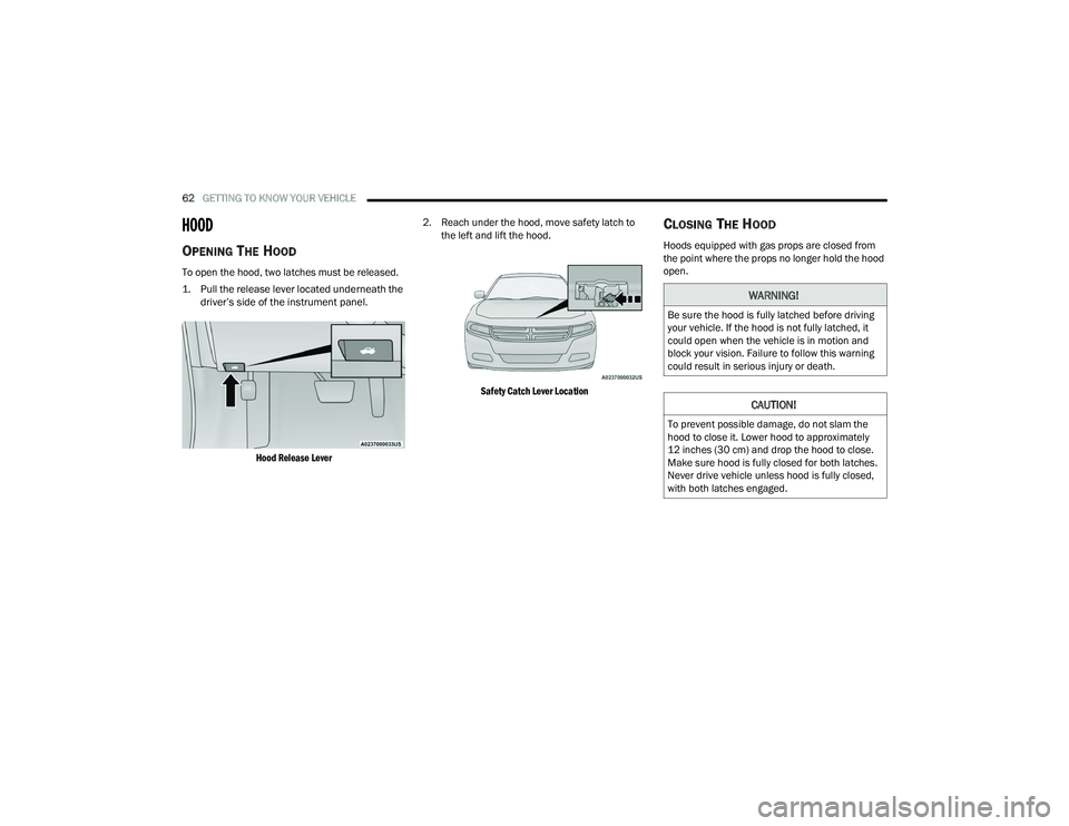
To open the hood, two latches must be released.
1. Pull the release lever located underneath the
driver’s side of the instrument panel.
Hood Release Lever
2. Reach under the hood, move safety latch to
the left and lift the hood.
Safety Catch Lever Location
CLOSING THE HOOD
Hoods equipped with gas props are closed from
the point where the props no longer hold the hood
open.
WARNING!
Be sure the hood is fully latched before driving
your vehicle. If the hood is not fully latched, it
could open when the vehicle is in motion and
block your vision. Failure to follow this warning
could result in serious injury or death.
CAUTION!
To prevent possible damage, do not slam the
hood to close it. Lower hood to approximately
12 inches (30 cm) and drop the hood to close.
Make sure hood is fully closed for both latches.
Never drive vehicle unless hood is fully closed,
with both latches engaged.
21_LD_OM_EN_USC_t.book Page 62
Page 69 of 320
GETTING TO KNOW YOUR INSTRUMENT PANEL67
INSTRUMENT CLUSTER DESCRIPTIONS
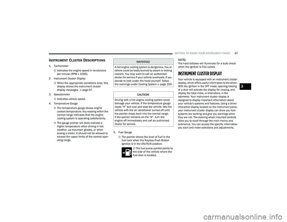
1. Tachometer
Indicates the engine speed in revolutions
per minute (RPM x 1000).
2. Instrument Cluster Display
When the appropriate conditions exist, this
display shows the instrument cluster
display messages Ú page 67.
3. Speedometer
Indicates vehicle speed.
4. Temperature Gauge
The temperature gauge shows engine
coolant temperature. Any reading within the
normal range indicates that the engine
cooling system is operating satisfactorily.
The gauge pointer will likely indicate a
higher temperature when driving in hot
weather, up mountain grades, or when
towing a trailer. It should not be allowed to
exceed the upper limits of the normal oper -
ating range. 5. Fuel Gauge
The pointer shows the level of fuel in the
fuel tank when the Keyless Push Button
Ignition is in the ON/RUN position.
The fuel pump symbol points to
the side of the vehicle where the
fuel door is located.
NOTE:The hard telltales will illuminate for a bulb check
when the ignition is first cycled.
INSTRUMENT CLUSTER DISPLAY
Your vehicle is equipped with an instrument cluster
display, which offers useful information to the driver.
With the ignition in the OFF mode, opening/closing
of a door will activate the display for viewing, and
display the total miles, or kilometers, in the
odometer. Your instrument cluster display is
designed to display important information about
your vehicle’s systems and features. Using a driver
interactive display located on the instrument panel,
your instrument cluster display can show you how
systems are working and give you warnings when
they are not. The steering wheel mounted controls
allow you to scroll through the main menus and
submenus. You can access the specific information
you want and make selections and adjustments.
WARNING!
A hot engine cooling system is dangerous. You or
others could be badly burned by steam or boiling
coolant. You may want to call an authorized
dealer for service if your vehicle overheats. If you
decide to look under the hood yourself, follow
the warnings under Cooling System Úpage 259.
CAUTION!
Driving with a hot engine cooling system could
damage your vehicle. If the temperature gauge
reads “H” pull over and stop the vehicle. Idle the
vehicle with the air conditioner turned off until
the pointer drops back into the normal range.
If the pointer remains on the “H”, turn the
engine off immediately and call an authorized
dealer for service.
3
21_LD_OM_EN_USC_t.book Page 67
Page 88 of 320
86STARTING AND OPERATING
AFTER STARTING
The idle speed is controlled automatically, and it
will decrease as the engine warms up.
ENGINE BLOCK HEATER — IF EQUIPPED
The engine block heater warms the engine, and
permits quicker starts in cold weather. Connect the
cord to a standard 110-115 Volt AC electrical
outlet with a grounded, three-wire extension cord.
The engine block heater must be plugged in at
least one hour to have an adequate warming effect
on the engine.
The engine block heater cord is routed under the
hood on the driver side of the vehicle. It has a
removable cap that is located near the air box.
ENGINE BREAK-IN RECOMMENDATIONS —
3.6L & 5.7L
A long break-in period is not required for the
drivetrain (engine, transmission, clutch, and rear
axle) in your new vehicle.
Drive moderately during the first 300 miles
(500 km). After the initial 60 miles (100 km),
speeds up to 50 or 55 mph (80 or 90 km/h) are
desirable. While cruising, brief full-throttle acceleration within
the limits of local traffic laws contributes to a good
break-in. However, wide-open throttle acceleration
in low gear can be detrimental and should be
avoided.
The engine oil, transmission fluid, and axle
lubricant installed at the factory is high-quality and
energy-conserving. Oil, fluid, and lubricant changes
should be consistent with anticipated climate and
conditions under which vehicle operations will
occur. For the recommended viscosity and quality
grades Ú
page 300.
NOTE:A new engine may consume some oil during its first
few thousand miles (kilometers) of operation.
This should be considered a normal part of the
break-in and not interpreted as an indication of
difficulty. Please check your oil level with the
engine oil indicator often during the break in
period. Add oil as required.
WARNING!
Never pour fuel or other flammable liquid into
the throttle body air inlet opening in an
attempt to start the vehicle. This could result
in flash fire causing serious personal injury.
Do not attempt to push or tow your vehicle to
get it started. Vehicles equipped with an auto -
matic transmission cannot be started this
way. Unburned fuel could enter the catalytic
converter and once the engine has started,
ignite and damage the converter and vehicle.
If the vehicle has a discharged battery,
booster cables may be used to obtain a start
from a booster battery or the battery in
another vehicle. This type of start can be
dangerous if done improperly Ú page 236.
CAUTION!
To prevent damage to the starter, do not
continuously crank the engine for more than
25 seconds at a time. Wait 60 seconds before
trying again.
WARNING!
Remember to disconnect the engine block
heater cord before driving. Damage to the
110-115 Volt electrical cord could cause
electrocution.
CAUTION!
Never use Non-Detergent Oil or Straight Mineral
Oil in the engine or damage may result.
21_LD_OM_EN_USC_t.book Page 86
Page 239 of 320
IN CASE OF EMERGENCY237
JUMP STARTING PROCEDURE
Connecting The Jumper Cables
1. Connect the positive
(+) end of the jumper
cable to the remote positive (+)
post of the
vehicle with the discharged battery.
2. Connect the opposite end of the positive (+)
jumper cable to the positive (+) post of the
booster battery.
3. Connect the negative (-) end of the jumper
cable to the negative (-) post of the booster
battery. 4. Connect the opposite end of the negative
(-)
jumper cable to the remote negative (-) post
(exposed metallic/unpainted post of the
discharge vehicle) located directly behind the
underhood fuse box.
5. Start the engine in the vehicle that has the booster battery, let the engine idle a few
minutes, and then start the engine in the
vehicle with the discharged battery.
WARNING!
Do not allow vehicles to touch each other as
this could establish a ground connection and
personal injury could result.
WARNING!
Take care to avoid the radiator cooling fan
whenever the hood is raised. It can start
anytime the ignition switch is ON. You can be
injured by moving fan blades.
Remove any metal jewelry such as rings,
watch bands and bracelets that could make
an inadvertent electrical contact. You could be
seriously injured.
Batteries contain sulfuric acid that can burn
your skin or eyes and generate hydrogen gas
which is flammable and explosive. Keep open
flames or sparks away from the battery.
WARNING!
Failure to follow this jump starting procedure
could result in personal injury or property
damage due to battery explosion.
CAUTION!
Failure to follow these procedures could result in
damage to the charging system of the booster
vehicle or the discharged vehicle.
WARNING!
Do not connect the jumper cable to the negative
(-) post of the discharged battery. The resulting
electrical spark could cause the battery to
explode and could result in personal injury.
CAUTION!
Do not run the booster vehicle engine above
2,000 RPM since it provides no charging benefit,
wastes fuel, and can damage booster vehicle
engine.
7
21_LD_OM_EN_USC_t.book Page 237
Page 242 of 320
240IN CASE OF EMERGENCY
MANUAL PARK RELEASE — 8-SPEED
TRANSMISSION
In order to move the vehicle in cases where the
transmission will not shift out of PARK (P) (such as
a depleted battery), a Manual Park Release is
available. Follow these steps to use the Manual Park
Release:
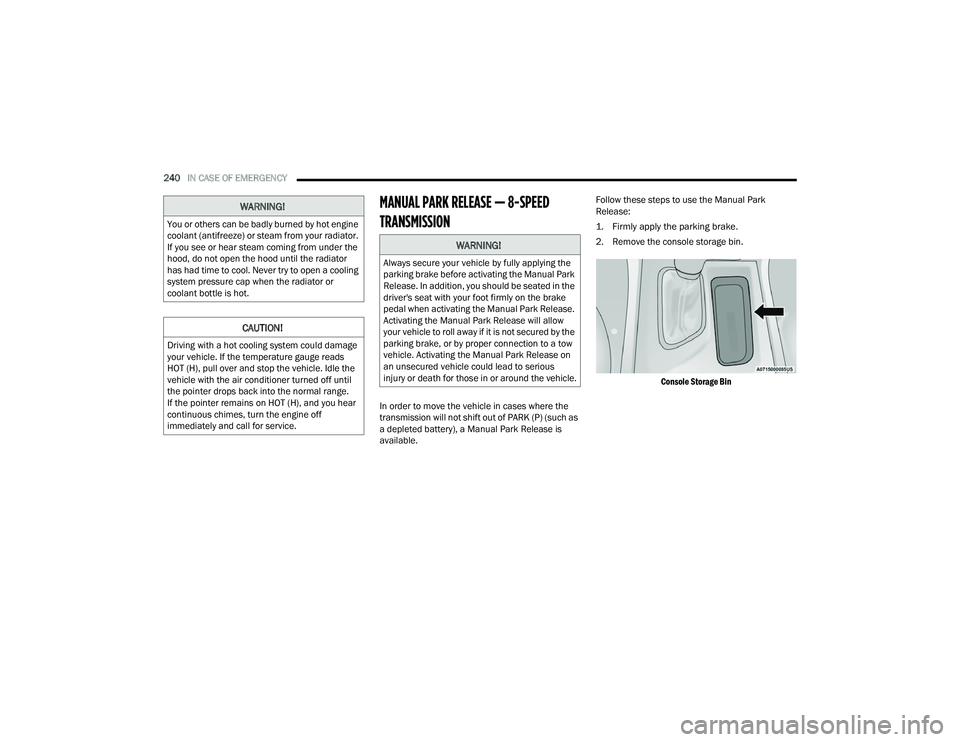
1. Firmly apply the parking brake.
2. Remove the console storage bin.
Console Storage Bin
WARNING!
You or others can be badly burned by hot engine
coolant (antifreeze) or steam from your radiator.
If you see or hear steam coming from under the
hood, do not open the hood until the radiator
has had time to cool. Never try to open a cooling
system pressure cap when the radiator or
coolant bottle is hot.
CAUTION!
Driving with a hot cooling system could damage
your vehicle. If the temperature gauge reads
HOT (H), pull over and stop the vehicle. Idle the
vehicle with the air conditioner turned off until
the pointer drops back into the normal range.
If the pointer remains on HOT (H), and you hear
continuous chimes, turn the engine off
immediately and call for service.
WARNING!
Always secure your vehicle by fully applying the
parking brake before activating the Manual Park
Release. In addition, you should be seated in the
driver's seat with your foot firmly on the brake
pedal when activating the Manual Park Release.
Activating the Manual Park Release will allow
your vehicle to roll away if it is not secured by the
parking brake, or by proper connection to a tow
vehicle. Activating the Manual Park Release on
an unsecured vehicle could lead to serious
injury or death for those in or around the vehicle.
21_LD_OM_EN_USC_t.book Page 240
Page 261 of 320
SERVICING AND MAINTENANCE259
Under normal operating conditions, the catalytic
converter will not require maintenance. However, it
is important to keep the engine properly tuned to
ensure proper catalyst operation and prevent
possible catalyst damage.
NOTE:Intentional tampering with emissions control
systems can result in civil penalties being
assessed against you.
In unusual situations involving grossly malfunctioning
engine operation, a scorching odor may suggest severe
and abnormal catalyst overheating. If this occurs, stop
the vehicle, turn off the engine and allow it to cool.
Service, including a tune-up to manufacturer's
specifications, should be obtained immediately.
To minimize the possibility of catalytic converter
damage:
Do not shut off the engine or interrupt the igni-
tion when the transmission is in gear and the
vehicle is in motion.
Do not try to start the engine by pushing or
towing the vehicle.
Do not idle the engine with any spark plug wires
disconnected or removed, such as when diag
-
nostic testing, or for prolonged periods during
very rough idle or malfunctioning operating
conditions.
NOTE:The vehicle exhaust system may be equipped with
an Electronic Exhaust Valve (EEV) system, if the
exhaust system is replaced with aftermarket
products a Malfunction Indicator Lamp (MIL) will
illuminate.
COOLING SYSTEM CAUTION!
The catalytic converter requires the use of
unleaded fuel only. Leaded gasoline will
destroy the effectiveness of the catalyst as an
emissions control device and may seriously
reduce engine performance and cause
serious damage to the engine.
Damage to the catalytic converter can result if
your vehicle is not kept in proper operating condi -
tion. In the event of engine malfunction, particu-
larly involving engine misfire or other apparent
loss of performance, have your vehicle serviced
promptly. Continued operation of your vehicle with
a severe malfunction could cause the converter to
overheat, resulting in possible damage to the
converter and vehicle.
WARNING!
You or others can be badly burned by hot
engine coolant (antifreeze) or steam from your
radiator. If you see or hear steam coming from
under the hood, do not open the hood until the
radiator has had time to cool. Never open a
cooling system pressure cap when the radi -
ator or coolant bottle is hot.
Keep hands, tools, clothing, and jewelry away
from the radiator cooling fan when the hood is
raised. The fan starts automatically and may
start at any time, whether the engine is
running or not.
When working near the radiator cooling fan,
disconnect the fan motor lead or turn the igni -
tion to the OFF mode. The fan is temperature
controlled and can start at any time the igni -
tion is in the ON mode.
8
21_LD_OM_EN_USC_t.book Page 259