sensor DODGE CHARGER 2021 Owners Manual
[x] Cancel search | Manufacturer: DODGE, Model Year: 2021, Model line: CHARGER, Model: DODGE CHARGER 2021Pages: 320, PDF Size: 20.61 MB
Page 6 of 320
4
STARTING AND OPERATING
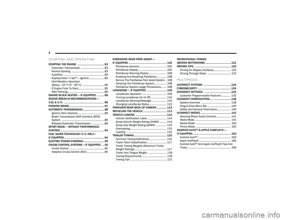
STARTING THE ENGINE ........................................ 83
Automatic Transmission .................................83
Normal Starting ...............................................83
AutoPark ...........................................................84
Keyless Enter ‘n Go™ — Ignition......................85
Cold Weather Operation
(Below –22°F Or −30°C) ...............................85
If Engine Fails To Start .....................................85
After Starting.....................................................86
ENGINE BLOCK HEATER — IF EQUIPPED ........... 86
ENGINE BREAK-IN RECOMMENDATIONS —
3.6L & 5.7L ........................................................... 86
PARKING BRAKE ................................................... 87
AUTOMATIC TRANSMISSION................................ 88 Ignition Park Interlock ......................................89
Brake Transmission Shift Interlock (BTSI)
System .............................................................89
8-Speed Automatic Transmission ...................89
SPORT MODE — WITHOUT PERFORMANCE
CONTROL ................................................................ 94
FUEL SAVER TECHNOLOGY 5.7L ONLY—
IF EQUIPPED ........................................................... 94
ELECTRIC POWER STEERING............................... 94
CRUISE CONTROL SYSTEMS — IF EQUIPPED ... 95
Cruise Control ...................................................95
Adaptive Cruise Control (ACC) .........................96 PARKSENSE REAR PARK ASSIST —
IF EQUIPPED ........................................................ 105
ParkSense Sensors ....................................... 105
ParkSense Display ........................................ 105ParkSense Warning Display ......................... 108
Enabling And Disabling ParkSense .............. 108
Service The ParkSense Park Assist System ...108
Cleaning The ParkSense System ................. 108
ParkSense System Usage Precautions........ 108
LANESENSE — IF EQUIPPED ............................. 109
LaneSense Operation ................................... 109Turning LaneSense On Or Off ....................... 110
LaneSense Warning Message ...................... 110Changing LaneSense Status ........................ 112
PARKVIEW REAR BACK UP CAMERA............... 112
REFUELING THE VEHICLE ................................... 113
VEHICLE LOADING ............................................. 114 Vehicle Certification Label ............................ 114
Gross Vehicle Weight Rating (GVWR) .......... 114
Gross Axle Weight Rating (GAWR) ............... 114
Overloading.................................................... 115
Loading ......................................................... 115
TRAILER TOWING ................................................ 115
Common Towing Definitions......................... 115
Trailer Hitch Classification ............................ 117
Trailer Towing Weights (Maximum Trailer
Weight Ratings) ............................................. 117Trailer And Tongue Weight ........................... 118Towing Requirements ................................... 118Towing Tips ................................................... 121 RECREATIONAL TOWING
(BEHIND MOTORHOME) ..................................... 121
DRIVING TIPS ....................................................... 122
Driving On Slippery Surfaces ........................ 122Driving Through Water ................................. 122
MULTIMEDIA
UCONNECT SYSTEMS ......................................... 124
CYBERSECURITY ................................................. 124
UCONNECT SETTINGS ........................................ 125 Customer Programmable Features ............. 125
UCONNECT INTRODUCTION................................ 138
System Overview .......................................... 138Drag & Drop Menu Bar ................................. 140
Safety And General Information................... 140
UCONNECT MODES ............................................. 141
Steering Wheel Audio Controls..................... 141Radio Mode .................................................. 141Media Mode ................................................. 150
Phone Mode ................................................. 152
ANDROID AUTO™ & APPLE CARPLAY® —
IF EQUIPPED ......................................................... 163
Android Auto™ .............................................. 163
Apple CarPlay® ............................................. 165Android Auto™ And Apple CarPlay® Tips And
Tricks.............................................................. 166
21_LD_OM_EN_USC_t.book Page 4
Page 75 of 320

GETTING TO KNOW YOUR INSTRUMENT PANEL73
BATTERY SAVER ON/BATTERY SAVER
M
ODE MESSAGE — ELECTRICAL LOAD
R
EDUCTION ACTIONS — IF EQUIPPED
This vehicle is equipped with an Intelligent Battery
Sensor (IBS) to perform additional monitoring of
the electrical system and status of the vehicle
battery.
In cases when the IBS detects charging system
failure, or the vehicle battery conditions are
deteriorating, electrical load reduction actions will
take place to extend the driving time and distance
of the vehicle. This is done by reducing power to or
turning off non-essential electrical loads.
Load reduction is only active when the engine is
running. It will display a message if there is a risk
of battery depletion to the point where the vehicle
may stall due to lack of electrical supply, or will not
restart after the current drive cycle.
When load reduction is activated, the message
“Battery Saver On” or “Battery Saver Mode” will
appear in the instrument cluster.
These messages indicate the vehicle battery has a
low state of charge and continues to lose electrical
charge at a rate that the charging system cannot
sustain.
NOTE:
The charging system is independent from load
reduction. The charging system performs a diag -
nostic on the charging system continuously.
If the Battery Charge Warning Light is on it may
indicate a problem with the charging system
Ú page 75.
The electrical loads that may be switched off
(if equipped), and vehicle functions which can be
affected by load reduction:
Heated Seat/Vented Seats/Heated Wheel
Heated/Cooled Cup Holders — If Equipped
Rear Defroster And Heated Mirrors
HVAC System
115 Volts AC Power Inverter System
Audio and Telematics System
Loss of the battery charge may indicate one or
more of the following conditions:
The charging system cannot deliver enough
electrical power to the vehicle system because
the electrical loads are larger than the capability
of the charging system. The charging system is
still functioning properly.
Turning on all possible vehicle electrical loads
(e.g. HVAC to max settings, exterior and interior
lights, overloaded power outlets +12 Volts,
115 Volts AC, USB ports) during certain driving
conditions (city driving, towing, frequent
stopping).
Installing options like additional lights, upfitter
electrical accessories, audio systems, alarms
and similar devices.
Unusual driving cycles (short trips separated by
long parking periods).
The vehicle was parked for an extended period
of time (weeks, months).
The battery was recently replaced and was not
charged completely.
The battery was discharged by an electrical load
left on when the vehicle was parked.
The battery was used for an extended period
with the engine not running to supply radio,
lights, chargers, +12 Volts portable appliances
like vacuum cleaners, game consoles and
similar devices.
3
21_LD_OM_EN_USC_t.book Page 73
Page 81 of 320
GETTING TO KNOW YOUR INSTRUMENT PANEL79
Each tire, including the spare (if provided), should be
checked monthly when cold and inflated to the inflation
pressure recommended by the vehicle manufacturer
on the vehicle placard or tire inflation pressure label.
If your vehicle has tires of a different size than the
size indicated on the vehicle placard or tire inflation
pressure label, you should determine the proper tire
inflation pressure for those tires.
As an added safety feature, your vehicle has been
equipped with TPMS that illuminates a low tire
pressure telltale when one or more of your tires is
significantly underinflated. Accordingly, when the
low tire pressure telltale illuminates, you should
stop and check your tires as soon as possible, and
inflate them to the proper pressure. Driving on a
significantly underinflated tire causes the tire to
overheat and can lead to tire failure. Underinflation
also reduces fuel efficiency and tire tread life, and
may affect the vehicle’s handling and stopping
ability. Please note that the TPMS is not a substitute for
proper tire maintenance, and it is the driver’s
responsibility to maintain correct tire pressure,
even if underinflation has not reached the level to
trigger illumination of the TPMS low tire pressure
telltale.
Your vehicle has also been equipped with a TPMS
malfunction indicator to indicate when the system is
not operating properly. The TPMS malfunction indicator
is combined with the low tire pressure telltale. When
the system detects a malfunction, the telltale will flash
for approximately one minute and then remain
continuously illuminated. This sequence will continue
upon subsequent vehicle start-ups as long as the
malfunction exists. When the malfunction indicator
is illuminated, the system may not be able to detect
or signal low tire pressure as intended. TPMS
malfunctions may occur for a variety of reasons,
including the installation of replacement or alternate
tires or wheels on the vehicle that prevent the TPMS
from functioning properly. Always check the TPMS
malfunction telltale after replacing one or more tires or
wheels on your vehicle to ensure that the replacement
or alternate tires and wheels allow the TPMS to
continue to function properly.
YELLOW INDICATOR LIGHTS
Forward Collision Warning (FCW) OFF
Indicator Light — If Equipped
This indicator light illuminates to indicate
that Forward Collision Warning is off
Ú
page 188.
CAUTION!
Do not continue driving with one or more flat
tires as handling may be compromised. Stop the
vehicle, avoiding sharp braking and steering. If a
tire puncture occurs, repair immediately using
the dedicated tire repair kit and contact an
authorized dealer as soon as possible.
CAUTION!
The TPMS has been optimized for the original
equipment tires and wheels. TPMS pressures and
warning have been established for the tire size
equipped on your vehicle. Undesirable system
operation or sensor damage may result when using
replacement equipment that is not of the same size,
type, and/or style. Aftermarket wheels can cause
sensor damage. Using aftermarket tire sealants may
cause the Tire Pressure Monitoring System (TPMS)
sensor to become inoperable. After using an
aftermarket tire sealant it is recommended that you
take your vehicle to an authorized dealer to have
your sensor function checked.
3
21_LD_OM_EN_USC_t.book Page 79
Page 98 of 320
96STARTING AND OPERATING
To Vary The Speed Setting
To Increase Or Decrease The Set Speed
When the Cruise Control is set, you can increase
speed by pushing the SET (+) button, or decrease
speed by pushing the SET (-) button.
U.S. Speed (mph)
Pushing the SET (+) , or SET (-) button once will
result in a 1 mph speed adjustment. Each
subsequent tap of the button results in an
adjustment of 1 mph.
If the button is continually pushed, the set
speed will continue to adjust until the button
is released, then the new set speed will be
established.
Metric Speed (km/h)
Pushing the SET (+), or SET (-) button once will
result in a 1 km/h speed adjustment. Each
subsequent tap of the button results in an
adjustment of 1 km/h.
If the button is continually pushed, the set
speed will continue to adjust until the button
is released, then the new set speed will be
established.
To Accelerate For Passing
Press the accelerator as you would normally. When
the pedal is released, the vehicle will return to the
set speed.
USING CRUISE CONTROL ON HILLS
The transmission may downshift on hills to
maintain the vehicle set speed.
The Cruise Control system maintains speed up and
down hills. A slight speed change on moderate hills
is normal. On steep hills, a greater speed loss or
gain may occur so it may be preferable to drive
without Cruise Control.
To Resume Speed
To resume a previously set speed, push the RES
button and release. Resume can be used at any
speed above 20 mph (32 km/h).
To Deactivate
A tap on the brake pedal, pushing the CANC button,
or normal brake pressure will deactivate the Cruise
Control system without erasing the set speed from
memory. The following conditions will also deactivate the
Cruise Control without erasing the set speed from
memory:
Vehicle parking brake is applied
Stability event occurs
Gear selector is moved out of DRIVE
Engine overspeed occurs
Pushing the on/off button or placing the ignition in the
OFF position erases the set speed from memory.
ADAPTIVE CRUISE CONTROL (ACC)
Adaptive Cruise Control (ACC) increases the driving
convenience provided by Cruise Control while traveling
on highways and major roadways. However, it is not a
safety system and not designed to prevent collisions.
The Cruise Control function performs differently
Ú
page 95.
ACC will allow you to keep Cruise Control engaged in
light to moderate traffic conditions without the constant
need to reset your Cruise Control. ACC utilizes a radar
sensor and a forward facing camera designed to detect
a vehicle directly ahead of you.
WARNING!
Cruise Control can be dangerous where the
system cannot maintain a constant speed.
Your vehicle could go too fast for the conditions,
and you could lose control and have an accident.
Do not use Cruise Control in heavy traffic or on
roads that are winding, icy, snow-covered or
slippery.
21_LD_OM_EN_USC_t.book Page 96
Page 99 of 320
STARTING AND OPERATING97
(Continued)
(Continued)
NOTE:
If the ACC sensor detects a vehicle ahead, ACC
will apply limited braking or acceleration (not to
exceed the original set speed) automatically to
maintain a preset following distance, while
matching the speed of the vehicle ahead.
Any chassis/suspension or tire size modifica -
tions to the vehicle will affect the performance
of the Adaptive Cruise Control and Forward Colli -
sion Warning systems.
Fixed Speed Cruise Control (ACC not enabled)
will not detect vehicles directly ahead of you.
Always be aware of the feature selected
Ú page 305.
WARNING!
Adaptive Cruise Control (ACC) is a conve -
nience system. It is not a substitute for active
driver involvement. It is always the driver’s
responsibility to be attentive of road, traffic,
and weather conditions, vehicle speed,
distance to the vehicle ahead; and, most
importantly, brake operation to ensure safe
operation of the vehicle under all road condi -
tions. Your complete attention is always
required while driving to maintain safe control
of your vehicle. Failure to follow these warn -
ings can result in a collision and death or
serious personal injury.
The ACC system:
Does not react to pedestrians, oncoming
vehicles, and stationary objects (e.g., a
stopped vehicle in a traffic jam or a
disabled vehicle).
Cannot take street, traffic, and weather condi -
tions into account, and may be limited upon
adverse sight distance conditions.
Does not always fully recognize complex
driving conditions, which can result in
wrong or missing distance warnings.
Will bring the vehicle to a complete stop
while following a vehicle ahead and hold
the vehicle for two seconds in the stop
position. If the vehicle ahead does not
start moving within two seconds, the ACC
system will display a message that the
system will release the brakes and that
the brakes must be applied manually. An
audible chime will sound when the brakes
are released.
WARNING!
You should switch off the ACC system:
When driving in fog, heavy rain, heavy snow,
sleet, heavy traffic, and complex driving situa -
tions (i.e., in highway construction zones).
When entering a turn lane or highway off
ramp; when driving on roads that are winding,
icy, snow-covered, slippery, or have steep
uphill or downhill slopes.
When towing a trailer up or down steep slopes.
When circumstances do not allow safe driving
at a constant speed.
WARNING!
4
21_LD_OM_EN_USC_t.book Page 97
Page 103 of 320
STARTING AND OPERATING101
When ACC Is Active:
When you use the SET (-) button to decelerate, if
the engine’s braking power does not slow the
vehicle sufficiently to reach the set speed, the
brake system will automatically slow the vehicle.
The ACC system applies the brake down to a full
stop when following the vehicle in front. If your
vehicle follows the vehicle in front to a standstill,
your vehicle will release the brakes two seconds
after coming to a full stop.
The ACC system maintains set speed when
driving uphill and downhill. However, a slight
speed change on moderate hills is normal.
In addition, downshifting may occur while
climbing uphill or descending downhill. This is
normal operation and necessary to maintain set
speed. When driving uphill and downhill, the ACC
system will cancel if the braking temperature
exceeds normal range (overheated).
Setting The Following Distance In ACC
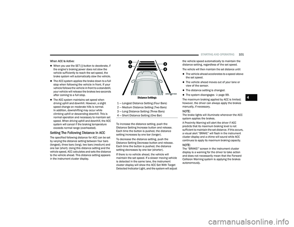
The specified following distance for ACC can be set
by varying the distance setting between four bars
(longest), three bars (long), two bars (medium) and
one bar (short). Using this distance setting and the
vehicle speed, ACC calculates and sets the distance
to the vehicle ahead. This distance setting appears
in the instrument cluster display. Distance Settings
To increase the distance setting, push the
Distance Setting Increase button and release.
Each time the button is pushed, the distance
setting increases by one bar (longer).
To decrease the distance setting, push the
Distance Setting Decrease button and release.
Each time the button is pushed, the distance
setting decreases by one bar (shorter).
If there is no vehicle ahead, the vehicle will
maintain the set speed. If a slower moving vehicle
is detected in the same lane, the instrument
cluster display will show the ACC Set With Target
Detected Indicator Light, and the system will adjust the vehicle speed automatically to maintain the
distance setting, regardless of the set speed.
The vehicle will then maintain the set distance until:
The vehicle ahead accelerates to a speed above
the set speed.
The vehicle ahead moves out of your lane or
view of the sensor.
The distance setting is changed.
The system disengages Ú
page 99.
The maximum braking applied by ACC is limited;
however, the driver can always apply the brakes
manually, if necessary.
NOTE:The brake lights will illuminate whenever the ACC
system applies the brakes.
A Proximity Warning will alert the driver if ACC
predicts that its maximum braking level is not
sufficient to maintain the set distance. If this occurs,
a visual alert “BRAKE” will flash in the instrument
cluster display and a chime will sound while ACC
continues to apply its maximum braking capacity.
NOTE:The “BRAKE!” screen in the instrument cluster
display is a warning for the driver to take action
and does not necessarily mean that the Forward
Collision Warning system is applying the brakes
autonomously.
1 — Longest Distance Setting (Four Bars)
2 — Medium Distance Setting (Two Bars)
3 — Long Distance Setting (Three Bars)
4 — Short Distance Setting (One Bar)
4
21_LD_OM_EN_USC_t.book Page 101
Page 104 of 320
102STARTING AND OPERATING
Overtake Aid
When driving with Adaptive Cruise Control (ACC)
engaged and following a vehicle, the system will
provide an additional acceleration up to the ACC
set speed to assist in passing the vehicle. This
additional acceleration is triggered when the driver
utilizes the left turn signal and will only be active
when passing on the left hand side.
ACC Operation At Stop
In the event that the ACC system brings your
vehicle to a standstill while following the vehicle in
front, if the vehicle in front starts moving within two
seconds of your vehicle coming to a standstill, your
vehicle will resume motion without the need for
any driver action.
If the vehicle in front does not start moving within
two seconds of your vehicle coming to a standstill,
the ACC with Stop system will cancel and the
brakes will release. A cancel message will display
on the instrument cluster display and produce a
warning chime. Driver intervention will be required
at this moment.
While ACC with Stop is holding your vehicle at a
standstill, if the driver seat belt is unbuckled or the
driver door is opened, the ACC with Stop system
will cancel and the brakes will release. A cancel
message will display on the instrument cluster
display and produce a warning chime. Driver
intervention will be required at this moment.
Display Warnings And Maintenance
“WIPE FRONT RADAR SENSOR IN FRONT OF
VEHICLE” WARNING
The “ACC/FCW Unavailable Wipe Front Radar
Sensor” warning will display and a chime will
sound when conditions temporarily limit system
performance.
This most often occurs at times of poor visibility,
such as in snow or heavy rain. The ACC system may
also become temporarily blinded due to
obstructions, such as mud, dirt or ice. In these
cases, the instrument cluster display will display
the above message and the system will deactivate.
This message can sometimes be displayed while
driving in highly reflective areas (i.e. ice and snow,
or tunnels with reflective tiles). The ACC system will
recover after the vehicle has left these areas.
Under rare conditions, when the radar is not
tracking any vehicles or objects in its path this
warning may temporarily occur.
NOTE:If the “ACC/FCW Unavailable Wipe Front Radar
Sensor” warning is active, Fixed Speed Cruise
Control is still available.
If weather conditions are not a factor, the driver
should examine the sensor. It may require cleaning
or removal of an obstruction. The sensor is located
in the center of the vehicle behind the lower grille.
To keep the ACC System operating properly, it is
important to note the following maintenance
items:
Always keep the sensor clean. Carefully wipe the
sensor lens with a soft cloth. Be cautious not to
damage the sensor lens.
Do not remove any screws from the sensor.
Doing so could cause an ACC system malfunc -
tion or failure and require a sensor realignment.
If the sensor or front end of the vehicle is
damaged due to a collision, see an authorized
dealer for service.
Do not attach or install any accessories near the
sensor, including transparent material or after -
market grilles. Doing so could cause an ACC
system failure or malfunction.
When the condition that deactivated the system is
no longer present, the system will return to the
“Adaptive Cruise Control Off” state and will resume
function by simply reactivating it.
WARNING!
When the ACC system is resumed, the driver
must ensure that there are no pedestrians,
vehicles or objects in the path of the vehicle.
Failure to follow these warnings can result in a
collision and death or serious personal injury.
21_LD_OM_EN_USC_t.book Page 102
Page 105 of 320
STARTING AND OPERATING103
NOTE:
If the “ACC/FCW Unavailable Wipe Front Radar
Sensor” message occurs frequently (e.g. more
than once on every trip) without any snow, rain,
mud, or other obstruction, have the radar
sensor realigned at an authorized dealer.
Installing a snow plow, front-end protector, an
aftermarket grille or modifying the grille is not
recommended. Doing so may block the sensor
and inhibit ACC/FCW operation.
“CLEAN FRONT WINDSHIELD” WARNING
The “ACC/FCW Limited Functionality Clean Front
Windshield” warning will display and a chime will
sound when conditions temporarily limit system
performance. This most often occurs at times of
poor visibility, such as in snow or heavy rain and
fog. The ACC system may also become temporarily
blinded due to obstructions, such as mud, dirt, or
ice on windshield and fog on the inside of glass.
In these cases, the instrument cluster display will
display “ACC/FCW Limited Functionality Clean
Front Windshield” and the system will have
degraded performance.
This message can sometimes be displayed while
driving in adverse weather conditions. The ACC/FCW
system will recover after the vehicle has left these
areas. Under rare conditions, when the camera is not
tracking any vehicles or objects in its path this warning
may temporarily occur.
If weather conditions are not a factor, the driver
should examine the windshield and the camera
located on the back side of the inside rearview
mirror. They may require cleaning or removal of an
obstruction.
When the condition that created limited functionality
is no longer present, the system will return to full
functionality.
NOTE:
If the “ACC/FCW Limited Functionality Clean Front
Windshield” message occurs frequently (e.g. more than
once on every trip) without any snow, rain, mud, or
other obstruction, have the windshield and forward
facing camera inspected at an authorized dealer.
SERVICE ACC/FCW WARNING
If the system turns off, and the instrument cluster
displays “ACC/FCW Unavailable Service Required” or
“Cruise/FCW Unavailable Service Required”, there may
be an internal system fault or a temporary malfunction
that limits ACC functionality. Although the vehicle is
still drivable under normal conditions, ACC will be
temporarily unavailable. If this occurs, try activating
ACC again later, following an ignition cycle. If the
problem persists, see an authorized dealer.
Precautions While Driving With ACC
In certain driving situations, ACC may have
detection issues. In these cases, ACC may brake
late or unexpectedly. The driver needs to stay alert
and may need to intervene. The following are
examples of these types of situations:
TOWING A TRAILER
Towing a trailer is not recommended when using ACC.
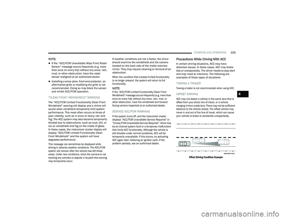
OFFSET DRIVING
ACC may not detect a vehicle in the same lane that is
offset from your direct line of travel, or a vehicle
merging in from a side lane. There may not be sufficient
distance to the vehicle ahead. The offset vehicle may
move in and out of the line of travel, which can cause
your vehicle to brake or accelerate unexpectedly.
Offset Driving Condition Example
4
21_LD_OM_EN_USC_t.book Page 103
Page 107 of 320
STARTING AND OPERATING105
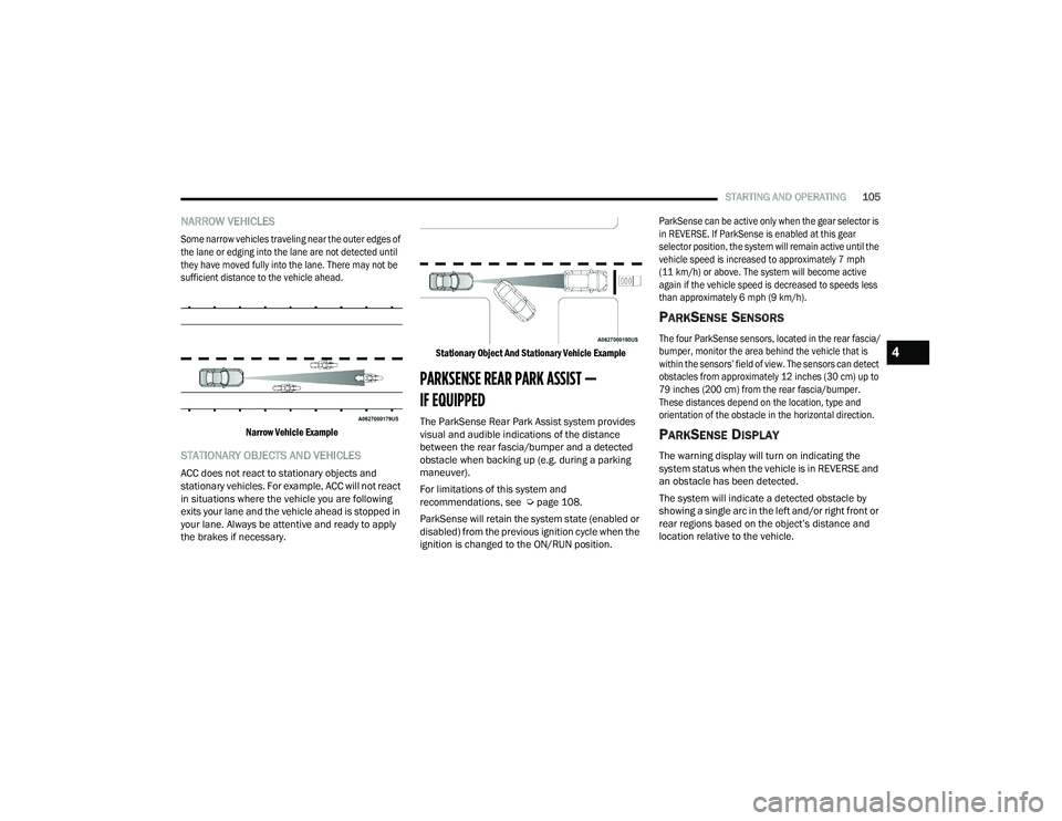
NARROW VEHICLES
Some narrow vehicles traveling near the outer edges of
the lane or edging into the lane are not detected until
they have moved fully into the lane. There may not be
sufficient distance to the vehicle ahead.
Narrow Vehicle Example
STATIONARY OBJECTS AND VEHICLES
ACC does not react to stationary objects and
stationary vehicles. For example, ACC will not react
in situations where the vehicle you are following
exits your lane and the vehicle ahead is stopped in
your lane. Always be attentive and ready to apply
the brakes if necessary.
Stationary Object And Stationary Vehicle Example
PARKSENSE REAR PARK ASSIST —
IF EQUIPPED
The ParkSense Rear Park Assist system provides
visual and audible indications of the distance
between the rear fascia/bumper and a detected
obstacle when backing up (e.g. during a parking
maneuver).
For limitations of this system and
recommendations, see Ú
page 108.
ParkSense will retain the system state (enabled or
disabled) from the previous ignition cycle when the
ignition is changed to the ON/RUN position.
ParkSense can be active only when the gear selector is
in REVERSE. If ParkSense is enabled at this gear
selector position, the system will remain active until the
vehicle speed is increased to approximately 7 mph
(11 km/h) or above. The system will become active
again if the vehicle speed is decreased to speeds less
than approximately 6 mph (9 km/h).
PARKSENSE SENSORS
The four ParkSense sensors, located in the rear fascia/
bumper, monitor the area behind the vehicle that is
within the sensors’ field of view. The sensors can detect
obstacles from approximately 12 inches (30 cm) up to
79 inches (200 cm) from the rear fascia/bumper.
These distances depend on the location, type and
orientation of the obstacle in the horizontal direction.
PARKSENSE DISPLAY
The warning display will turn on indicating the
system status when the vehicle is in REVERSE and
an obstacle has been detected.
The system will indicate a detected obstacle by
showing a single arc in the left and/or right front or
rear regions based on the object’s distance and
location relative to the vehicle.
4
21_LD_OM_EN_USC_t.book Page 105
Page 110 of 320
108STARTING AND OPERATING
Adjustable Chime Volume Settings
Rear chime volume settings can be selected from
the Uconnect system Ú page 125.
The chime volume settings include low, medium,
and high.
ParkSense will retain its last known configuration
state through ignition cycles.
PARKSENSE WARNING DISPLAY
The ParkSense Warning screen will only be
displayed if Sound and Display is selected from
within the Uconnect system Ú page 125.
The ParkSense Warning screen is located within the
instrument cluster display
Ú
page 67. It provides
visual warnings to indicate the distance between the
rear fascia/bumper and the detected obstacle.
ENABLING AND DISABLING PARKSENSE
ParkSense can be enabled and disabled
with the ParkSense switch.
When the ParkSense switch is pushed to disable
the system, the instrument cluster will display
the “ParkSense Off” message for approximately
five seconds. When the gear selector is moved to
REVERSE and the system is disabled, the instrument
cluster display will display the “ParkSense Off”
message for as long as the vehicle is in REVERSE.
The ParkSense switch LED will be on when
ParkSense is disabled or requires service. The
ParkSense switch LED will be off when the system is
enabled. If the ParkSense switch is pushed and the
system requires service, the ParkSense switch LED
will blink momentarily and then the LED will be on.
SERVICE THE PARKSENSE PARK ASSIST
S
YSTEM
During vehicle start up, when the ParkSense Rear Park
Assist System has detected a faulted condition, the
instrument cluster display will actuate a single chime,
once per ignition cycle, and it will display the
“PARKSENSE UNAVAILABLE WIPE REAR SENSORS” or
the “PARKSENSE UNAVAILABLE SERVICE REQUIRED”
message. When the gear selector is moved to REVERSE
and the system has detected a faulted condition, the
instrument cluster display will show the "PARKSENSE
UNAVAILABLE WIPE REAR SENSORS" or "PARKSENSE
UNAVAILABLE SERVICE REQUIRED" message for as
long as the vehicle is in REVERSE. Under this condition,
ParkSense will not operate.
If “PARKSENSE UNAVAILABLE WIPE REAR
SENSORS” appears in the instrument cluster
display, make sure the outer surface and the
underside of the rear fascia/bumper is clean and
clear of snow, ice, mud, dirt or other obstruction and
then cycle the ignition. If the message continues to
appear, see an authorized dealer.
If “PARKSENSE UNAVAILABLE SERVICE
REQUIRED” appears in the instrument cluster
display, see an authorized dealer.
CLEANING THE PARKSENSE SYSTEM
Clean the ParkSense sensors with water, car wash
soap and a soft cloth. Do not use rough or hard
cloths. Do not scratch or poke the sensors.
Otherwise, you could damage the sensors.
PARKSENSE SYSTEM USAGE
P
RECAUTIONS
NOTE:
Ensure that the rear fascia/bumper is free of
snow, ice, mud, dirt and debris to keep the
ParkSense system operating properly.
Jackhammers, large trucks, and other vibrations
could affect the performance of ParkSense.
When you turn ParkSense off in DRIVE, the
instrument cluster will display "PARKSENSE
OFF" for five seconds. Furthermore, once you
turn ParkSense off, it remains off until you turn
it on again, even if you cycle the ignition.
21_LD_OM_EN_USC_t.book Page 108