remote start DODGE CHARGER 2022 User Guide
[x] Cancel search | Manufacturer: DODGE, Model Year: 2022, Model line: CHARGER, Model: DODGE CHARGER 2022Pages: 312, PDF Size: 18.99 MB
Page 53 of 312
GETTING TO KNOW YOUR VEHICLE51
Remote Start Mode Inhibit — On vehicles
equipped with the Remote Start system, Rain
Sensing wipers are not operational when the
vehicle is in the Remote Start mode.
CLIMATE CONTROLS
The Climate Control system allows you to regulate
the temperature, air flow, and direction of air
circulating throughout the vehicle. The controls are
located on the touchscreen (if equipped) and on
the instrument panel below the radio.
AUTOMATIC CLIMATE CONTROL
D
ESCRIPTIONS AND FUNCTIONS
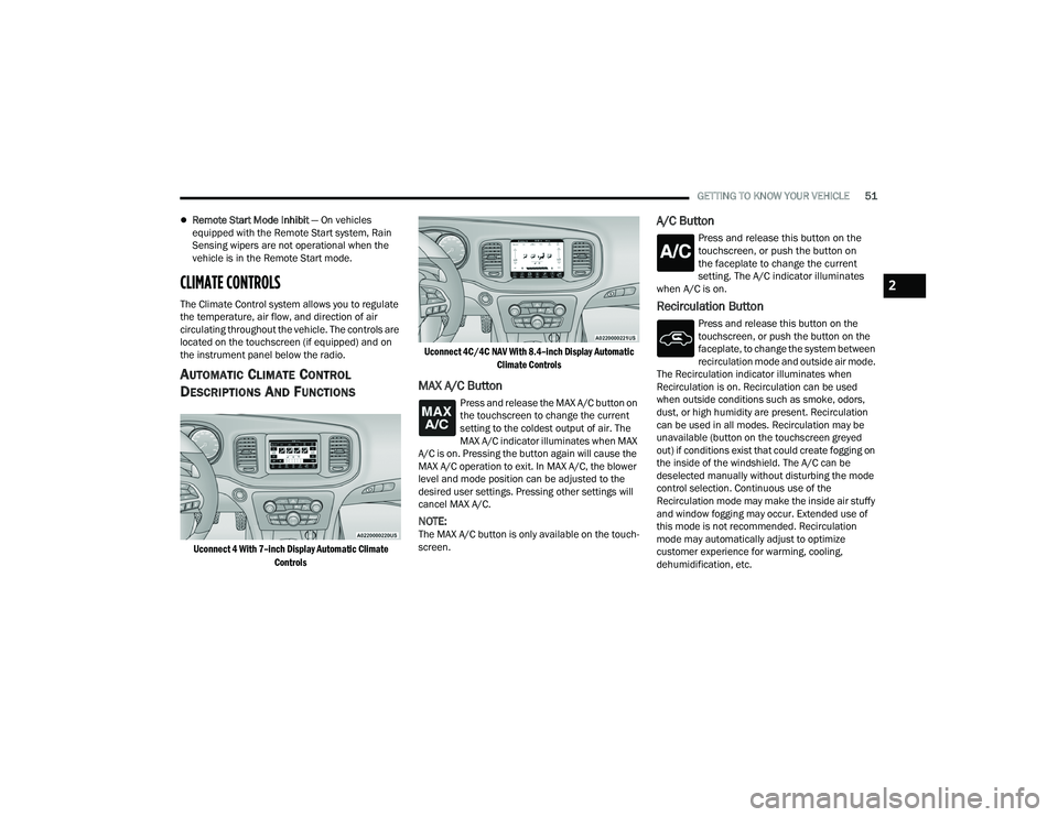
Uconnect 4 With 7–inch Display Automatic Climate
Controls Uconnect 4C/4C NAV With 8.4–inch Display Automatic
Climate Controls
MAX A/C Button
Press and release the MAX A/C button on
the touchscreen to change the current
setting to the coldest output of air. The
MAX A/C indicator illuminates when MAX
A/C is on. Pressing the button again will cause the
MAX A/C operation to exit. In MAX A/C, the blower
level and mode position can be adjusted to the
desired user settings. Pressing other settings will
cancel MAX A/C.
NOTE:The MAX A/C button is only available on the touch -
screen.
A/C Button
Press and release this button on the
touchscreen, or push the button on
the faceplate to change the current
setting. The A/C indicator illuminates
when A/C is on.
Recirculation Button
Press and release this button on the
touchscreen, or push the button on the
faceplate, to change the system between
recirculation mode and outside air mode.
The Recirculation indicator illuminates when
Recirculation is on. Recirculation can be used
when outside conditions such as smoke, odors,
dust, or high humidity are present. Recirculation
can be used in all modes. Recirculation may be
unavailable (button on the touchscreen greyed
out) if conditions exist that could create fogging on
the inside of the windshield. The A/C can be
deselected manually without disturbing the mode
control selection. Continuous use of the
Recirculation mode may make the inside air stuffy
and window fogging may occur. Extended use of
this mode is not recommended. Recirculation
mode may automatically adjust to optimize
customer experience for warming, cooling,
dehumidification, etc.
2
22_LD_OM_EN_USC_t.book Page 51
Page 88 of 312

86STARTING AND OPERATING
NOTE:For Keyless Enter ’n Go™ equipped vehicles, the
engine will turn off and the ignition switch will
change to ACC position.
If the vehicle is not in PARK and the driver exits the
vehicle with the engine running, the vehicle may
AutoPark.
AutoPark will engage when all of these conditions
are met:
Vehicle is equipped with an 8-speed transmis -
sion
Vehicle is not in PARK
Vehicle speed is 1.2 mph (1.9 km/h) or less
Driver’s seat belt is unbuckled
Driver’s door is ajar
Brake pedal is not pressed
The message “ AutoPark Engaged Shift to P then
Shift to Gear ” will display in the instrument cluster.
NOTE:In some cases the ParkSense graphic will be
displayed in the instrument cluster. In these cases,
the gear selector must be returned to “P” to select
desired gear. If the driver shifts into PARK while moving, the
vehicle may AutoPark.
AutoPark will engage
ONLY when vehicle speed is
1.2 mph (1.9 km/h) or less.
The message “ Vehicle Speed is Too High to Shift
to P ” will be displayed in the instrument cluster if
vehicle speed is above 1.2 mph (1.9 km/h).
ALWAYS DO A VISUAL CHECK
that your vehicle is in
PARK by looking for the "P" in the instrument
cluster display and on the gear selector. As an
added precaution, always apply the parking brake
when exiting the vehicle.
KEYLESS ENTER ‘N GO™ — IGNITION
This feature allows the driver to operate the
ignition switch with the push of a button, as long as
the Remote Start/Keyless Enter ’n Go™ key fob is
in the passenger compartment.
EXTENDED PARK STARTING
NOTE:Extended Park condition occurs when the vehicle
has not been started or driven for at least 30 days.
1. Install a battery charger or jumper cables to the battery to ensure a full battery charge
during the crank cycle.
2. Place the ignition in the START position and release it when the engine starts.
3. If the engine fails to start within 10 seconds, place the ignition in the OFF position, wait 10
to 15 seconds to allow the starter to cool, then
repeat the “Extended Park Starting”
procedure.
4. If the engine fails to start after eight attempts, allow the starter to cool for at least
10 minutes, then repeat the procedure.
WARNING!
If vehicle speed is above 1.2 mph (1.9 km/h),
the transmission will default to NEUTRAL until
the vehicle speed drops below 1.2 mph
(1.9 km/h). A vehicle left in the NEUTRAL
position can roll. As an added precaution,
always apply the parking brake when exiting the
vehicle.
CAUTION!
To prevent damage to the starter, do not crank
continuously for more than 10 seconds at a
time. Wait 10 to 15 seconds before trying again.
22_LD_OM_EN_USC_t.book Page 86
Page 134 of 312
132MULTIMEDIA
Doors & Locks
When the Doors & Locks button is pressed on the touchscreen, the system displays the options related to locking and unlocking the vehicle’s doors.
NOTE:Depending on the vehicle’s options, feature settings may vary.
Setting Name Description
Auto Unlock On ExitThis setting will unlock the doors when any of the doors are opened from the
inside.
Flash Lights With Lock This setting will allow you to turn on or off the flashing of the lights when the
Lock button is pushed on the key fob. Available settings are “On” and “Off”.
Sound Horn With Lock This setting will sound the horn when the Lock button is pushed on the key
fob. The “Off” setting will not sound the horn when the Lock button is pushed. The “1st Press” setting will sound the horn when the Lock button is pushed once. The “2nd Press” setting will sound the horn when the Lock button is pushed twice.
Sound Horn With Remote Start This setting will sound the horn when the remote start is activated from the
key fob.
1st Press Of Key Fob Unlocks This setting will change how many pushes of the Unlock button on the key fob
are needed to unlock all the doors. The “Driver Door” setting will only unlock
the driver door on the first push on the Unlock button. The “All Doors” setting will unlock all doors on the first push of the Unlock button.
Passive Entry This setting will allow you to turn the Passive Entry feature
(Keyless Enter ‘n Go™) on or off.
Personal Settings Linked To Key Fob This setting will recall preset radio stations and driver seat position that have
been linked to the key fob.
22_LD_OM_EN_USC_t.book Page 132
Page 135 of 312
MULTIMEDIA133
Seats & Comfort
Key Off Options
When Seats & Comfort button is pressed on the touchscreen, the system displays the option related to the vehicle’s comfort systems when remote start has
been activated or the vehicle has been started.
NOTE:Depending on the vehicle’s options, feature settings may vary.
Setting Name Description
Auto-On Driver Heated/Ventilated Seat & Steering Wheel With Vehicle Start
This setting will activate the vehicle’s comfort systems and heated seats or heated
steering wheel when the vehicle is remote started or ignition is started. The “Off” setting will not activate the comfort systems. The “Remote Start” setting (if
equipped) will only activate the comfort systems when using Remote Start. The “All Start” setting will activate the comfort systems whenever the vehicle is started.
When the Key Off Options button is pressed on the touchscreen, the system displays the options related to vehicle shut off. These settings will only activate
when the ignition is set to OFF.
NOTE:Depending on the vehicle’s options, feature settings may vary.
Setting Name Description
Easy Exit SeatThis setting adjusts the seats to make exiting the vehicle easier.
Key Off Power Delay This setting will keep certain electrical features running after the engine is
turned off. When any door is opened, the electronics will deactivate. The available settings are “0 sec”, “45 sec”, “5 min”, and “10 min”.
Headlight Off Delay This setting will allow you to set the amount of time the headlights remain on
after the vehicle has been turned off. The available settings are “0 sec”, “30 sec”, “60 sec”, and “90 sec”.
5
22_LD_OM_EN_USC_t.book Page 133
Page 228 of 312
226IN CASE OF EMERGENCY
(Continued)
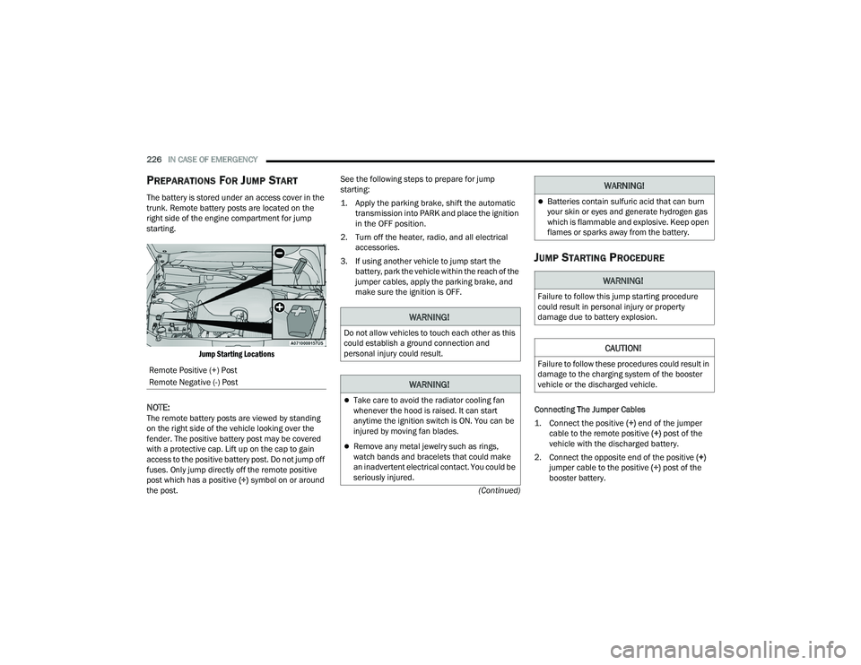
PREPARATIONS FOR JUMP START
The battery is stored under an access cover in the
trunk. Remote battery posts are located on the
right side of the engine compartment for jump
starting.
Jump Starting Locations
NOTE:The remote battery posts are viewed by standing
on the right side of the vehicle looking over the
fender. The positive battery post may be covered
with a protective cap. Lift up on the cap to gain
access to the positive battery post. Do not jump off
fuses. Only jump directly off the remote positive
post which has a positive (+) symbol on or around
the post. See the following steps to prepare for jump
starting:
1. Apply the parking brake, shift the automatic
transmission into PARK and place the ignition
in the OFF position.
2. Turn off the heater, radio, and all electrical accessories.
3. If using another vehicle to jump start the battery, park the vehicle within the reach of the
jumper cables, apply the parking brake, and
make sure the ignition is OFF.
JUMP STARTING PROCEDURE
Connecting The Jumper Cables
1. Connect the positive
(+) end of the jumper
cable to the remote positive (+)
post of the
vehicle with the discharged battery.
2. Connect the opposite end of the positive (+)
jumper cable to the positive (+) post of the
booster battery.
Remote Positive (+) Post
Remote Negative (-) Post
WARNING!
Do not allow vehicles to touch each other as this
could establish a ground connection and
personal injury could result.
WARNING!
Take care to avoid the radiator cooling fan
whenever the hood is raised. It can start
anytime the ignition switch is ON. You can be
injured by moving fan blades.
Remove any metal jewelry such as rings,
watch bands and bracelets that could make
an inadvertent electrical contact. You could be
seriously injured.
Batteries contain sulfuric acid that can burn
your skin or eyes and generate hydrogen gas
which is flammable and explosive. Keep open
flames or sparks away from the battery.
WARNING!
Failure to follow this jump starting procedure
could result in personal injury or property
damage due to battery explosion.
CAUTION!
Failure to follow these procedures could result in
damage to the charging system of the booster
vehicle or the discharged vehicle.
WARNING!
22_LD_OM_EN_USC_t.book Page 226
Page 229 of 312
IN CASE OF EMERGENCY227
3. Connect the negative (-) end of the jumper
cable to the negative (-) post of the booster
battery.
4. Connect the opposite end of the negative (-)
jumper cable to the remote negative (-) post
(exposed metallic/unpainted post of the
discharge vehicle) located directly behind the
underhood fuse box.
5. Start the engine in the vehicle that has the booster battery, let the engine idle a few
minutes, and then start the engine in the
vehicle with the discharged battery.
6. Once the engine is started, follow the discon -
nection procedure. Disconnecting The Jumper Cables
1. Disconnect the negative
(-) end of the jumper
cable from the remote negative (-)
post of the
vehicle with the discharged battery.
2. Disconnect the opposite end of the negative (-)
jumper cable from the negative (-) post of the
booster battery.
3. Disconnect the positive (+) end of the jumper
cable from the positive (+) post of the booster
battery.
4. Disconnect the opposite end of the positive (+)
jumper cable from the remote positive (+) post
of the vehicle with the discharged battery, and
reinstall the protective cap.
If frequent jump starting is required to start your
vehicle you should have the battery and charging
system inspected at an authorized dealer.
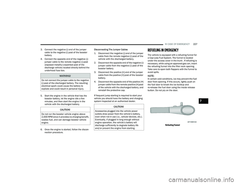
REFUELING IN EMERGENCY
The vehicle is equipped with a refueling funnel for
a Cap-Less Fuel System. The funnel is located
under the access cover in the trunk . If refueling is
necessary, while using an approved gas can, insert
the refueling funnel into the filler neck opening.
Take care to open both flappers with the funnel to
avoid spills.
NOTE:In certain cold conditions, ice may prevent the fuel
door from opening. If this occurs, lightly push on
the fuel door to break the ice buildup and
re-release the fuel door using the inside release
button. Do not pry on the door.
Refueling Funnel
WARNING!
Do not connect the jumper cable to the negative
(-) post of the discharged battery. The resulting
electrical spark could cause the battery to
explode and could result in personal injury.
CAUTION!
Do not run the booster vehicle engine above
2,000 RPM since it provides no charging benefit,
wastes fuel, and can damage booster vehicle
engine.
CAUTION!
Accessories plugged into the vehicle power
outlets draw power from the vehicle’s battery,
even when not in use (i.e., cellular devices, etc.).
Eventually, if plugged in long enough without
engine operation, the vehicle’s battery will
discharge sufficiently to degrade battery life
and/or prevent the engine from starting.
7
22_LD_OM_EN_USC_t.book Page 227
Page 243 of 312
SERVICING AND MAINTENANCE241
(Continued)
(Continued)
MAINTENANCE-FREE BATTERY
Your vehicle is equipped with a maintenance-free
battery. Water will never have to be added, and
periodic maintenance is not required.
NOTE:The battery is stored under an access cover in the
trunk. Remote battery terminals are located in the
engine compartment for jump starting
Ú
page 225.
PRESSURE WASHING
Cleaning the engine compartment with a high
pressure washer is not recommended.
VEHICLE MAINTENANCE
An authorized dealer has the qualified service
personnel, special tools, and equipment to
perform all service operations in an expert
manner. Service Manuals are available which
include detailed service information for your
vehicle. Refer to these Service Manuals before
attempting any procedure yourself.
WARNING!
Commercially available windshield washer
solvents are flammable. They could ignite and
burn you. Care must be exercised when filling or
working around the washer solution.
WARNING!
Battery fluid is a corrosive acid solution and
can burn or even blind you. Do not allow
battery fluid to contact your eyes, skin, or
clothing. Do not lean over a battery when
attaching clamps. If acid splashes in eyes or
on skin, flush the area immediately with large
amounts of water Ú page 225.
Battery gas is flammable and explosive. Keep
flame or sparks away from the battery. Do not
use a booster battery or any other booster
source with an output greater than 12 Volts.
Do not allow cable clamps to touch each
other.
Battery posts, terminals, and related accesso -
ries contain lead and lead compounds. Wash
hands after handling.
The battery in this vehicle has a vent hose that
should not be disconnected and should only
be replaced with a battery of the same type
(vented).
CAUTION!
It is essential when replacing the cables on
the battery that the positive cable is attached
to the positive post and the negative cable is
attached to the negative post. Battery posts
are marked positive (+) and negative (-) and
are identified on the battery case. Cable
clamps should be tight on the terminal posts
and free of corrosion.
WARNING!
If a “fast charger” is used while the battery is
in the vehicle, disconnect both vehicle battery
cables before connecting the charger to the
battery. Do not use a “fast charger” to provide
starting voltage.
CAUTION!
Precautions have been taken to safeguard all
parts and connections however, the pressures
generated by these machines is such that
complete protection against water ingress
cannot be guaranteed.
CAUTION!
8
22_LD_OM_EN_USC_t.book Page 241
Page 261 of 312
SERVICING AND MAINTENANCE259
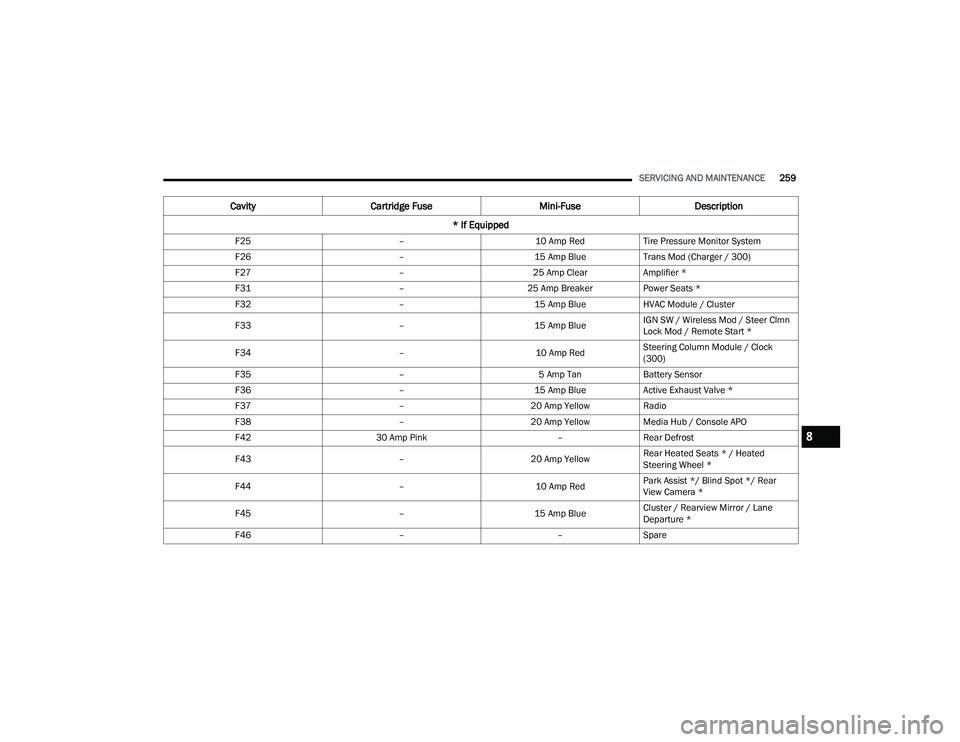
F25 –10 Amp RedTire Pressure Monitor System
F26 –15 Amp BlueTrans Mod (Charger / 300)
F27 –25 Amp ClearAmplifier *
F31 –25 Amp BreakerPower Seats *
F32 –15 Amp BlueHVAC Module / Cluster
F33 –15 Amp BlueIGN SW / Wireless Mod / Steer Clmn
Lock Mod / Remote Start *
F34 –10 Amp RedSteering Column Module / Clock
(300)
F35 –5 Amp TanBattery Sensor
F36 –15 Amp BlueActive Exhaust Valve *
F37 –20 Amp YellowRadio
F38 –20 Amp YellowMedia Hub / Console APO
F42 30 Amp Pink –Rear Defrost
F43 –20 Amp YellowRear Heated Seats * / Heated
Steering Wheel *
F44 –10 Amp RedPark Assist */ Blind Spot */ Rear
View Camera *
F45 –15 Amp BlueCluster / Rearview Mirror / Lane
Departure *
F46 ––Spare
Cavity Cartridge Fuse Mini-FuseDescription
* If Equipped
8
22_LD_OM_EN_USC_t.book Page 259
Page 301 of 312
299
Cooling System
.............................................. 248Adding Coolant (Antifreeze)....................... 249Coolant Level.................................. 248, 250Cooling Capacity........................................ 290Disposal Of Used Coolant.......................... 250Drain, Flush, And Refill.............................. 248Inspection................................................. 250Points To Remember................................. 250Pressure Cap............................................. 249Radiator Cap............................................. 249Selection Of Coolant (Antifreeze)........................ 248, 290, 291Corrosion Protection...................................... 283Cruise Control (Speed Control)................. 95, 96Cruise Light.............................................. 81, 82Customer Assistance..................................... 293Customer Programmable Features................123Cybersecurity................................................. 123
D
Daytime Running Lights................................... 45Deck LidPower Release............................................ 65Defroster, Windshield.................................... 210De-Icer, Remote Start...................................... 20Deleting A Phone........................................... 156
Deluxe Security Alarm...................................... 21Diagnostic System, Onboard............................ 82Dimmer SwitchHeadlight..................................................... 45DipsticksOil (Engine)............................................... 240Disabled Vehicle Towing............................... 232Disc Drive..................................................... 150Disconnecting............................................... 156DisposalAntifreeze (Engine Coolant)...................... 250Disturb.......................................................... 159Door Ajar.......................................................... 77Door Ajar Light................................................. 77Door LocksAutomatic.................................................... 26Child-Protection Door Lock — Rear Doors.... 26Doors............................................................... 22Drag & Drop.................................................. 140Driver Memory Presets................................. 147Driver’s Seat Back Tilt...................................... 31DrivingThrough Flowing, Rising, Or Shallow Standing Water
................................................... 122
E
Electric Brake Control System....................... 169Anti-Lock Brake System............................ 168Electronic Roll Mitigation................. 170, 173Electric Remote Mirrors...................................39
Electronic Power Distribution Center (Fuses).. 253
Electronic Speed Control (Cruise Control)........95Electronic Stability Control (ESC)................... 170Electronic Throttle Control Warning Light.........77Emergency Gas Can Refueling...................... 227Emergency, In Case OfFreeing Vehicle When Stuck..................... 231Hazard Warning Flasher........................... 213Jacking...................................................... 216Jump Starting.................................. 225, 226Towing...................................................... 232Emission Control System Maintenance............83Engine.................................................. 238, 239Air Cleaner................................................ 243Break-In Recommendations........................87Checking Oil Level.................................... 240Compartment.................................. 238, 239Compartment Identification...................... 238Coolant (Antifreeze)......................... 248, 291Cooling...................................................... 248Exhaust Gas Caution....................... 211, 212
11
22_LD_OM_EN_USC_t.book Page 299
Page 303 of 312
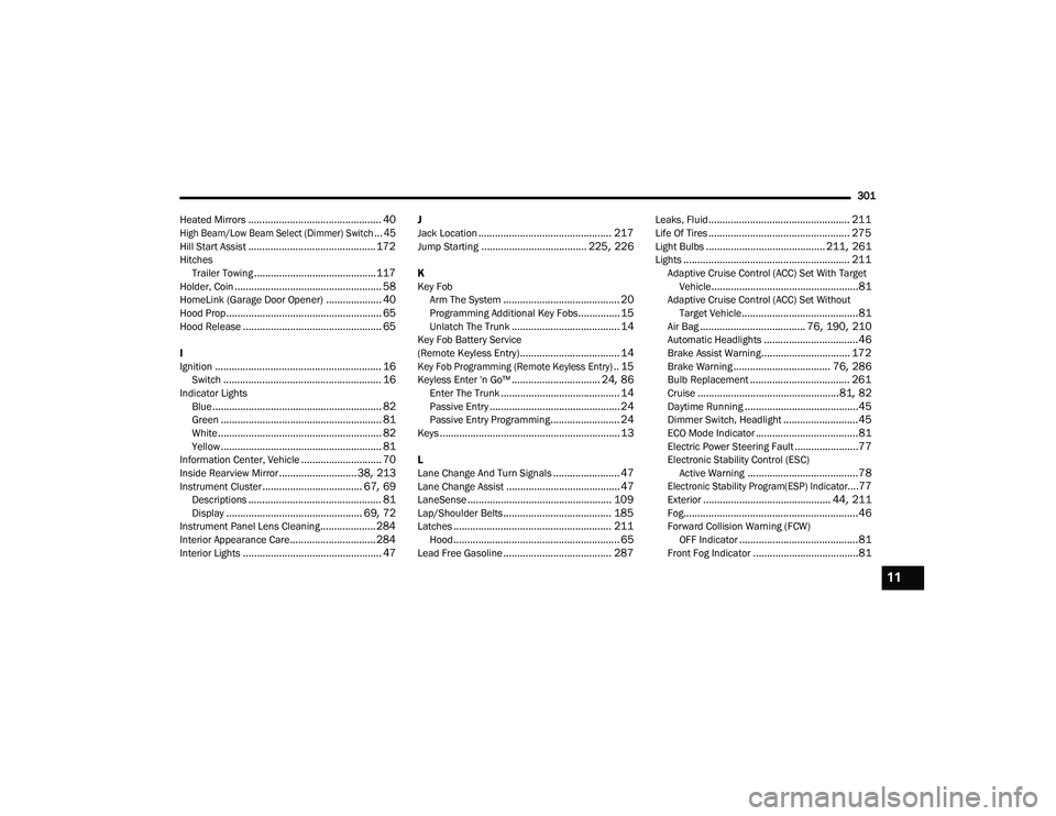
301
Heated Mirrors
................................................ 40
High Beam/Low Beam Select (Dimmer) Switch... 45
Hill Start Assist.............................................. 172Hitches Trailer Towing............................................ 117Holder, Coin..................................................... 58HomeLink (Garage Door Opener).................... 40Hood Prop........................................................ 65Hood Release.................................................. 65
I
Ignition............................................................ 16Switch......................................................... 16Indicator LightsBlue............................................................. 82Green.......................................................... 81White........................................................... 82Yellow.......................................................... 81Information Center, Vehicle............................. 70Inside Rearview Mirror............................ 38, 213Instrument Cluster.................................... 67, 69Descriptions................................................ 81Display................................................. 69, 72Instrument Panel Lens Cleaning.................... 284Interior Appearance Care............................... 284Interior Lights.................................................. 47
J
Jack Location................................................ 217Jump Starting...................................... 225, 226
K
Key FobArm The System
.......................................... 20Programming Additional Key Fobs............... 15Unlatch The Trunk....................................... 14Key Fob Battery Service
(Remote Keyless Entry).................................... 14
Key Fob Programming (Remote Keyless Entry).. 15
Keyless Enter 'n Go™................................ 24, 86Enter The Trunk........................................... 14Passive Entry............................................... 24Passive Entry Programming......................... 24Keys................................................................. 13
L
Lane Change And Turn Signals........................ 47Lane Change Assist......................................... 47LaneSense.................................................... 109Lap/Shoulder Belts....................................... 185Latches......................................................... 211Hood............................................................ 65Lead Free Gasoline....................................... 287
Leaks, Fluid................................................... 211Life Of Tires................................................... 275Light Bulbs........................................... 211, 261Lights............................................................ 211Adaptive Cruise Control (ACC) Set With Target Vehicle.....................................................81Adaptive Cruise Control (ACC) Set WithoutTarget Vehicle..........................................81Air Bag...................................... 76, 190, 210Automatic Headlights..................................46Brake Assist Warning................................ 172Brake Warning................................... 76, 286Bulb Replacement.................................... 261Cruise...................................................81, 82Daytime Running.........................................45Dimmer Switch, Headlight...........................45ECO Mode Indicator.....................................81Electric Power Steering Fault.......................77Electronic Stability Control (ESC)Active Warning........................................78
Electronic Stability Program(ESP) Indicator....77
Exterior.............................................. 44, 211Fog...............................................................46Forward Collision Warning (FCW) OFF Indicator...........................................81Front Fog Indicator......................................81
11
22_LD_OM_EN_USC_t.book Page 301