How to turn off car DODGE CHARGER 2022 Owners Manual
[x] Cancel search | Manufacturer: DODGE, Model Year: 2022, Model line: CHARGER, Model: DODGE CHARGER 2022Pages: 312, PDF Size: 18.99 MB
Page 20 of 312
18GETTING TO KNOW YOUR VEHICLE
HOW TO USE REMOTE START
Push and release the Remote Start button on the
key fob twice within five seconds. The vehicle
doors will lock, the parking lights will flash, and the
horn will chirp twice (if programmed). Then, the
engine will start, and the vehicle will remain in the
Remote Start mode for a 15 minute cycle. Pushing
the Remote Start button a third time shuts the
engine off.
To drive the vehicle, push the unlock button, and
with a valid Keyless Enter ‘n Go™ key fob in the
vehicle, press the brake pedal and place the
ignition in the ON/RUN position.
NOTE:
With Remote Start, the engine will only run for
15 minutes.
Remote Start can only be used twice.
If an engine fault is present or fuel level is low,
the vehicle will start and then shut down in 10
seconds.
The parking lights will turn on and remain on
during Remote Start mode.
For security, power window operation is
disabled when the vehicle is in the Remote Start
mode.
The ignition must be placed in the ON/RUN posi -
tion before the Remote Start sequence can be
repeated for a third cycle.
All of the following conditions must be met before
the engine will remote start:
Gear selector in PARK
Doors closed
Hood closed
Trunk closed
Hazard switch off
Brake switch inactive (brake pedal not pressed)
Battery at an acceptable charge level
Check engine light shall not be present
PANIC button not pushed
System not disabled from previous Remote
Start event
Vehicle Security system indicator flashing
Ignition in the OFF position
Fuel level meets minimum requirement
Vehicle Security system is not signaling an intrusion
Malfunction Indicator Light (MIL) is not illumi -
nated
TO EXIT REMOTE START MODE
To drive the vehicle after starting the Remote Start
system, either push and release the unlock button
on the key fob to unlock the doors, or unlock the
vehicle using Keyless Enter ‘n Go™ — Passive Entry
via the door handles, and disarm the Vehicle
WARNING!
Do not start or run an engine in a closed
garage or confined area. Exhaust gas contains
Carbon Monoxide (CO) which is odorless and
colorless. Carbon Monoxide is poisonous and
can cause serious injury or death when
inhaled.
Keep key fobs away from children. Operation
of the Remote Start system, windows, door
locks or other controls could cause serious
injury or death.
WARNING!
Do not start or run an engine in a closed
garage or confined area. Exhaust gas contains
Carbon Monoxide (CO) which is odorless and
colorless. Carbon Monoxide is poisonous and
can cause serious injury or death when
inhaled.
Keep key fobs away from children. Operation
of the Remote Start system, windows, door
locks or other controls could cause serious
injury or death.
22_LD_OM_EN_USC_t.book Page 18
Page 110 of 312
108STARTING AND OPERATING
Adjustable Chime Volume Settings
Rear chime volume settings can be selected from
the Uconnect system Ú page 123.
The chime volume settings include low, medium,
and high.
ParkSense will retain its last known configuration
state through ignition cycles.
PARKSENSE WARNING DISPLAY
The ParkSense Warning screen will only be
displayed if Sound and Display is selected from
within the Uconnect system Ú page 123.
The ParkSense Warning screen is located within
the instrument cluster display Ú page 69. It
provides visual warnings to indicate the distance
between the rear fascia/bumper and the detected
obstacle.
ENABLING AND DISABLING PARKSENSE
ParkSense can be enabled and disabled
with the ParkSense switch.
When the ParkSense switch is pushed to
disable the system, the instrument cluster will
display the “ParkSense Off” message for
approximately five seconds. When the gear
selector is moved to REVERSE and the system is
disabled, the instrument cluster display will display
the “ParkSense Off” message for as long as the
vehicle is in REVERSE.
The ParkSense switch LED will be on when
ParkSense is disabled or requires service. The
ParkSense switch LED will be off when the system
is enabled. If the ParkSense switch is pushed and
the system requires service, the ParkSense
switch LED will blink momentarily and then the
LED will be on.
SERVICE THE PARKSENSE PARK ASSIST
S
YSTEM
During vehicle start up, when the ParkSense Rear
Park Assist System has detected a faulted
condition, the instrument cluster display will
actuate a single chime, once per ignition cycle, and
it will display the “PARKSENSE UNAVAILABLE WIPE
REAR SENSORS” or the “PARKSENSE
UNAVAILABLE SERVICE REQUIRED” message.
When the gear selector is moved to REVERSE and
the system has detected a faulted condition, the
instrument cluster display will show the
"PARKSENSE UNAVAILABLE WIPE REAR SENSORS"
or "PARKSENSE UNAVAILABLE SERVICE
REQUIRED" message for as long as the vehicle is in
REVERSE. Under this condition, ParkSense will not
operate.
If “PARKSENSE UNAVAILABLE WIPE REAR
SENSORS” appears in the instrument cluster
display, make sure the outer surface and the
underside of the rear fascia/bumper is clean and
clear of snow, ice, mud, dirt or other obstruction and then cycle the ignition. If the message
continues to appear, see an authorized dealer.
If “PARKSENSE UNAVAILABLE SERVICE
REQUIRED” appears in the instrument cluster
display, see an authorized dealer.
CLEANING THE PARKSENSE SYSTEM
Clean the ParkSense sensors with water, car wash
soap and a soft cloth. Do not use rough or hard
cloths. Do not scratch or poke the sensors.
Otherwise, you could damage the sensors.
PARKSENSE SYSTEM USAGE
P
RECAUTIONS
NOTE:
Ensure that the rear fascia/bumper is free of
snow, ice, mud, dirt and debris to keep the
ParkSense system operating properly.
Jackhammers, large trucks, and other vibra -
tions could affect the performance of
ParkSense.
When you turn ParkSense off in DRIVE, the
instrument cluster will display "PARKSENSE
OFF" for five seconds. Furthermore, once you
turn ParkSense off, it remains off until you turn
it on again, even if you cycle the ignition.
22_LD_OM_EN_USC_t.book Page 108
Page 111 of 312
STARTING AND OPERATING109
When you move the gear selector to the
REVERSE position and ParkSense is turned off,
the instrument cluster display will show the
“PARKSENSE OFF” message for as long as the
vehicle is in REVERSE.
ParkSense will reduce the volume of the radio
when it is sounding an audio tone.
Clean the ParkSense sensors regularly, taking
care not to scratch or damage them. The
sensors must not be covered with ice, snow,
slush, mud, dirt or debris. Failure to do so can
result in the system not working properly. The
ParkSense system might not detect an obstacle
behind the fascia/bumper, or it could provide a
false indication that an obstacle is behind the
fascia/bumper.
Use the ParkSense switch to turn the ParkSense
system off if objects such as bicycle carriers,
trailer hitches, etc. are placed within 12 inches
(30 cm) from the rear fascia/bumper. Failure to
do so can result in the system misinterpreting a
close object as a sensor problem, causing the
“PARKSENSE UNAVAILABLE WIPE REAR
SENSORS” message to be displayed in the
instrument cluster.
LANESENSE — IF EQUIPPED
LANESENSE OPERATION
The LaneSense system is operational at speeds
above 37 mph (60 km/h) and below 112 mph
(180 km/h). The LaneSense system uses a
forward looking camera to detect lane markings
and measure vehicle position within the lane
boundaries.
When both lane markings are detected and the
driver unintentionally drifts out of the lane (no turn
signal applied), the LaneSense system provides a
haptic warning in the form of torque applied to the
steering wheel to prompt the driver to remain
within the lane boundaries. If the driver
unintentionally drifts out of the lane, the
LaneSense system provides a visual warning
through the instrument cluster display to prompt
the driver to remain within the lane boundaries.
The driver may manually override the haptic
warning by applying torque to the steering wheel at
any time.
When only a single lane marking is detected and
the driver drifts across the lane marking (no turn
signal applied), the LaneSense system provides
visual warnings through the instrument cluster
display to prompt the driver to remain within the
lane. When only a single lane marking is detected,
a haptic or a torque warning will not be provided.
WARNING!
Drivers must be careful when backing up even
when using ParkSense. Always check carefully
behind your vehicle, look behind you, and be
sure to check for pedestrians, animals, other
vehicles, obstructions, and blind spots before
backing up. You are responsible for safety and
must continue to pay attention to your
surroundings. Failure to do so can result in
serious injury or death.
CAUTION!
ParkSense is only a parking aid and it is
unable to recognize every obstacle, including
small obstacles. Parking curbs might be
temporarily detected or not detected at all.
Obstacles located above or below the sensors
will not be detected when they are in close
proximity.
The vehicle must be driven slowly when using
ParkSense in order to be able to stop in time
when an obstacle is detected. It is recom -
mended that the driver looks over his/her
shoulder when using ParkSense.
4
22_LD_OM_EN_USC_t.book Page 109
Page 114 of 312
112STARTING AND OPERATING
CHANGING LANESENSE STATUS
The LaneSense system has settings to adjust the
intensity of the torque warning and the warning
zone sensitivity (early/med/late) that you can
configure through the Uconnect system
Úpage 123.
NOTE:
When enabled the system operates above
37 mph (60 km/h) and below 112 mph
(180 km/h).
The warnings are disabled with the use of the
turn signal.
The system will not apply torque to the steering
wheel whenever a safety system engages
(Anti-Lock Brakes, Traction Control System,
Electronic Stability Control, Forward Collision
Warning, etc.).
PARKVIEW REAR BACK UP CAMERA
The ParkView Rear Back Up Camera allows you to
see an on-screen image of the rear surroundings of
your vehicle whenever the gear selector is put into
REVERSE. The image will be displayed on the
Navigation/Multimedia radio display screen along
with a caution note to “Check Entire Surroundings”
across the top of the screen. After five seconds this
note will disappear. The ParkView Rear Back Up Camera is located on the rear of the vehicle above
the rear license plate.
NOTE:The ParkView Rear Back Up Camera has program
-
mable modes of operation that may be selected
through the Uconnect system Ú page 123.
When the vehicle is shifted out of REVERSE with
camera delay turned off, the rear camera mode is
exited and the previous screen appears. When the
vehicle is shifted out of REVERSE with camera
delay turned on, the camera image will continue to
be displayed for up to 10 seconds unless the
following conditions occur: The vehicle speed
exceeds 8 mph (13 km/h), the vehicle is shifted
into PARK, the vehicle’s ignition is placed in the
OFF position, or the user presses image defeat X to
exit out of the camera video display.
When manually activated, a counter will be
initiated after the vehicle speed is above 8 mph
(13 km/h). The rear view camera image will turn
off when this counter reaches 10 seconds. The
counter will be reset when the vehicle speed is
8 mph (13 km/h) or below. If the vehicle speed
remains below 8 mph (13 km/h), the rear view
camera image will continue to be displayed until
the transmission is shifted into PARK, the vehicle’s
ignition is placed in the OFF position, or the image
defeat X button is pressed. When enabled, active guidelines are overlaid on
the image to illustrate the width of the vehicle and
its projected backup path based on the steering
wheel position. Different colored zones indicate
the distance to the rear of the vehicle. The
following table shows the approximate distances
for each zone:
Zone Distance To The Rear Of
The Vehicle
Red 0 - 1 ft (0 - 30 cm)
Yellow 1 ft - 6.5 ft (30 cm - 2 m)
Green 6.5 ft or greater
(2 m or greater)
WARNING!
Drivers must be careful when backing up even
when using the ParkView Rear Back Up Camera.
Always check carefully behind your vehicle, and
be sure to check for pedestrians, animals, other
vehicles, obstructions, or blind spots before
backing up. You are responsible for the safety of
your surroundings and must continue to pay
attention while backing up. Failure to do so can
result in serious injury or death.
22_LD_OM_EN_USC_t.book Page 112
Page 116 of 312
114STARTING AND OPERATING
VEHICLE LOADING
The load carrying capacity of your vehicle is shown
on the Vehicle Certification Label. This information
should be used for passenger and luggage loading
as indicated.
Do not exceed the specified Gross Vehicle Weight
Rating (GVWR) or the Gross Axle Weight Rating
(GAWR).
VEHICLE CERTIFICATION LABEL
Your vehicle has a Vehicle Certification Label
affixed to the driver’s side B-pillar or the rear of the
driver’s door.
The label contains the following information:
Name of manufacturer.
Month and year of manufacture.
Gross Vehicle Weight Rating (GVWR).
Gross Axle Weight Rating (GAWR) front.
Gross Axle Weight Rating (GAWR) rear.
Vehicle Identification Number (VIN).
Type of vehicle.
Month, Day, and Hour (MDH) of manufacture.
The bar code allows a computer scanner to read
the VIN.
GROSS VEHICLE WEIGHT RATING
(GVWR)
The GVWR is the total allowable weight of your
vehicle. This includes driver, passengers, and
cargo. The total load must be limited so that you do
not exceed the GVWR.
GROSS AXLE WEIGHT RATING (GAWR)
The GAWR is the maximum capacity of the front
and rear axles. Distribute the load over the front
and rear axles evenly. Make sure that you do not
exceed either front or rear GAWR.
OVERLOADING
The load carrying components (axle, springs, tires,
wheels, etc.) of your vehicle will provide
satisfactory service as long as you do not exceed
the GVWR and the front and rear GAWR.
The best way to figure out the total weight of your
vehicle is to weigh it when it is fully loaded and
ready for operation. Weigh it on a commercial scale
to ensure that it is not over the GVWR.
Figure out the weight on the front and rear of the
vehicle separately. It is important that you
distribute the load evenly over the front and rear
axles.
Never add fuel when the engine is running.
This is in violation of most state and federal
fire regulations and may cause the Malfunc -
tion Indicator Light to turn on.
A fire may result if fuel is pumped into a
portable container that is inside of a vehicle.
You could be burned. Always place fuel
containers on the ground while filling.
CAUTION!
To avoid fuel spillage and overfilling, do not “top
off” the fuel tank after filling.
WARNING!
WARNING!
Because the front wheels steer the vehicle, it is
important that you do not exceed the maximum
front or rear GAWR. A dangerous driving
condition can result if either rating is exceeded.
You could lose control of the vehicle and have a
collision.
22_LD_OM_EN_USC_t.book Page 114
Page 169 of 312
MULTIMEDIA167
ANDROID AUTO™ AND APPLE
C
ARPLAY® TIPS AND TRICKS
Android Auto™ And Apple CarPlay® Automatic
Bluetooth® Pairing
After connecting to Android Auto™ or Apple
CarPlay® for the first time and undergoing the
setup procedure, the smartphone pairs to the
Uconnect system via Bluetooth® without any setup
required every time it is within range, if Bluetooth®
is turned on.
NOTE:Apple CarPlay® uses a USB connection while
Android Auto™ uses both USB and Bluetooth®
connections to function. The connected device is
unavailable to other devices when connected
using Android Auto™ or Apple CarPlay®.
Multiple Devices Connecting To The Uconnect
System — If Equipped
It is possible to have multiple devices connected to
the Uconnect system. For example, if using Android
Auto™/Apple CarPlay®, the connected device will
be used to place hands-free phone calls or send
hands-free text messages. However, another
device can also be paired to the Uconnect system,
via Bluetooth®, as an audio source, so the
passenger can stream music.
NOTE:Apple CarPlay® and Android Auto™ can only be
launched from the front and center console USB
ports.
RADIO OPERATION AND MOBILE PHONES
Under certain conditions, the mobile phone being
on in your vehicle can cause erratic or noisy
performance from your radio. This condition may
be lessened or eliminated by repositioning the
mobile phone within the vehicle. This condition is
not harmful to the radio. If your radio performance
does not satisfactorily improve from repositioning
the mobile phone, it is recommended that the
volume be turned down or off during mobile phone
operation when not using the Uconnect system.
REGULATORY AND SAFETY
I
NFORMATION
US/CANADA
Exposure to Radio Frequency Radiation
The radiated output power of the internal wireless
radio is far below the FCC and IC radio frequency
exposure limits. Nevertheless, the wireless radio
will be used in such a manner that the radio is 8 in
(20 cm) or further from the human body. The internal wireless radio operates within
guidelines found in radio frequency safety
standards and recommendations, which reflect
the consensus of the scientific community.
The radio manufacturer believes the internal
wireless radio is safe for use by consumers. The
level of energy emitted is far less than the
electromagnetic energy emitted by wireless
devices such as mobile phones. However, the use
of wireless radios may be restricted in some
situations or environments, such as aboard
airplanes. If you are unsure of restrictions, you are
encouraged to ask for authorization before turning
on the wireless radio Ú
page 296.
5
22_LD_OM_EN_USC_t.book Page 167
Page 179 of 312
SAFETY177
NOTE:In a parking lot situation, oncoming vehicles can be
blocked by vehicles parked on either side. If the
sensors are blocked by other structures or
vehicles, the system will not be able to alert the
driver.
Blind Spot Modes
Blind Spot Alert Lights Only
Blind Spot has three selectable modes of
operation that are available in the Uconnect
system.
When operating in Blind Spot Alert mode, the BSM
system will provide a visual alert in the appropriate
side view mirror based on a detected object.
However, when the system is operating in Rear
Cross Path mode, the system will respond with both visual and audible alerts when a detected
object is present. Whenever an audible alert is
requested, the radio volume is reduced so that the
alert can be better heard.
Blind Spot Alert Lights/Chime
When operating in Blind Spot Alert Lights/Chime
mode, the BSM system will provide a visual alert in
the appropriate side view mirror based on a
detected object. If the turn signal is then activated,
and it corresponds to an alert present on that side
of the vehicle, an audible chime will also be
sounded. Whenever a turn signal and detected
object are present on the same side at the same
time, both the visual and audio alerts will be
issued. In addition to the audible alert the radio (if
on) volume will be reduced so that the alert can be
better heard.
When the system is in RCP, the system shall
respond with both visual and audible alerts when a
detected object is present. Whenever an audible
alert is requested, the radio volume is reduced so
that the alert can be better heard.
Blind Spot Alert Off
When the BSM system is turned off there will be no
visual or audible alerts from either the BSM or RCP
systems.
NOTE:The BSM system will store the current operating
mode when the vehicle is shut off. Each time the
vehicle is started the previously stored mode will
be recalled and used.
FORWARD COLLISION WARNING (FCW)
W
ITH MITIGATION OPERATION
FCW with Mitigation provides the driver with
audible warnings, visual warnings (within the
instrument cluster display), and may apply haptic
warning in the form of a a brake jerk, to warn the
driver when it detects a potential frontal collision.
The warnings and limited braking are intended to
provide the driver with enough time to react, avoid
or mitigate the potential collision.
NOTE:FCW monitors the information from the forward
looking sensors, as well as the Electronic Stability
Control (ESC) system, to calculate the probability of
a forward collision. When the system determines
that a forward collision is probable, the driver will
be provided with audible and visual warnings and
may provide a brake jerk warning. If the driver does
not take action based upon these progressive
warnings, then the system will provide a limited
level of active braking to help slow the vehicle and
mitigate the potential forward collision. If the driver
reacts to the warnings by braking and the system
determines that the driver intends to avoid the
WARNING!
Rear Cross Path Detection (RCP) is not a back up
aid system. It is intended to be used to help a
driver detect an oncoming vehicle in a parking
lot situation. Drivers must be careful when
backing up, even when using RCP. Always check
carefully behind your vehicle, look behind you,
and be sure to check for pedestrians, animals,
other vehicles, obstructions, and blind spots
before backing up. Failure to do so can result in
serious injury or death.
6
22_LD_OM_EN_USC_t.book Page 177
Page 181 of 312
SAFETY179
NOTE:The “Far” setting may result in a greater number of
FCW possible collision warnings experienced.
Changing the FCW status to the “Near” setting,
allows the system to warn you of a possible
collision with the vehicle in front of you when you
are much closer. This setting provides less
reaction time than the “Far” setting, which allows
for a more dynamic driving experience.
NOTE:The “Near” setting may result in a lesser number of
FCW possible collision warnings experienced.
NOTE:
The system will retain the last setting selected
by the driver after ignition shut down.
FCW may not react to irrelevant objects such as
overhead objects, ground reflections, objects
not in the path of the vehicle, stationary objects
that are far away, oncoming traffic, or leading
vehicles with the same or higher rate of speed.
FCW disables in the same manner as ACC, and
will display a screen indicating that the feature
is unavailable when it has been disabled.
FCW Limited Warning
If the instrument cluster display reads “ACC/FCW
Limited Functionality” or “ACC/FCW Limited
Functionality Clean Front Windshield”
momentarily, there may be a condition that limits
FCW functionality. Although the vehicle is still drivable under normal conditions, the active
braking may not be fully available. Once the
condition that limited the system performance is
no longer present, the system will return to its full
performance state. If the problem persists, see an
authorized dealer.
Service FCW Warning
If the system turns off, and the instrument cluster
display reads:
ACC/FCW Unavailable Service Required
Cruise/FCW Unavailable Service Required
This indicates there is an internal system fault.
Although the vehicle is still drivable under normal
conditions, have the system checked by an
authorized dealer.
TIRE PRESSURE MONITORING SYSTEM
(TPMS)
The Tire Pressure Monitoring System (TPMS) will
warn the driver of a low tire pressure based on the
vehicle recommended cold placard pressure.
The tire pressure will vary with temperature by about
1 psi (7 kPa) for every 12°F (6.5°C). This means that
when the outside temperature decreases, the tire
pressure will decrease. Tire pressure should always
be set based on cold inflation tire pressure. This is
defined as the tire pressure after the vehicle has not
been driven for at least three hours, or driven less
than 1 mile (1.6 km) after a three hour period. The cold tire inflation pressure must not exceed the
maximum inflation pressure molded into the tire
sidewall. The tire pressure will also increase as the
vehicle is driven — this is normal and there should be
no adjustment for this increased pressure.
See Ú
page 264 for information on how to
properly inflate the vehicle’s tires.
The TPMS will warn the driver of a low tire pressure
if the tire pressure falls below the low-pressure
warning limit for any reason, including low
temperature effects and natural pressure loss
through the tire.
The TPMS will continue to warn the driver of low
tire pressure as long as the condition exists, and
will not turn off until the tire pressure is at or above
the recommended cold placard pressure. Once the
low tire pressure warning (TPMS Warning Light)
illuminates, you must increase the tire pressure to
the recommended cold placard pressure in order
for the TPMS Warning Light to turn off. The system
will automatically update and the TPMS Warning
Light will turn off once the system receives the
updated tire pressures. The vehicle may need to be
driven for up to 20 minutes above 15 mph
(24 km/h) in order for the TPMS to receive this
information.
6
22_LD_OM_EN_USC_t.book Page 179
Page 183 of 312
SAFETY181
Premium System
The Tire Pressure Monitoring System (TPMS) uses
wireless technology with wheel rim mounted
electronic sensors to monitor tire pressure levels.
Sensors, mounted to each wheel as part of the
valve stem, transmit tire pressure readings to the
receiver module.
NOTE:It is particularly important for you to check the tire
pressure in all of the tires on your vehicle monthly
and to maintain the proper pressure.
The TPMS consists of the following components:
Receiver module
Four Tire Pressure Monitoring System sensors
Various Tire Pressure Monitoring System messages,
which display in the instrument cluster
Tire Pressure Monitoring System Warning Light
Tire Pressure Monitoring System Low
Pressure Warnings
The Tire Pressure Monitoring System
(TPMS) Warning Light will illuminate in
the instrument cluster and a chime will
sound when tire pressure is low in one or
more of the four active road tires. In addition, the
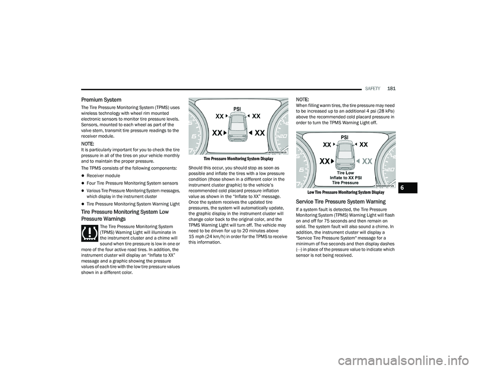
instrument cluster will display an “Inflate to XX”
message and a graphic showing the pressure
values of each tire with the low tire pressure values
shown in a different color.
Tire Pressure Monitoring System Display
Should this occur, you should stop as soon as
possible and inflate the tires with a low pressure
condition (those shown in a different color in the
instrument cluster graphic) to the vehicle’s
recommended cold placard pressure inflation
value as shown in the “Inflate to XX” message.
Once the system receives the updated tire
pressures, the system will automatically update,
the graphic display in the instrument cluster will
change color back to the original color, and the
TPMS Warning Light will turn off. The vehicle may
need to be driven for up to 20 minutes above
15 mph (24 km/h) in order for the TPMS to receive
this information.
NOTE:When filling warm tires, the tire pressure may need
to be increased up to an additional 4 psi (28 kPa)
above the recommended cold placard pressure in
order to turn the TPMS Warning Light off.
Low Tire Pressure Monitoring System Display
Service Tire Pressure System Warning
If a system fault is detected, the Tire Pressure
Monitoring System (TPMS) Warning Light will flash
on and off for 75 seconds and then remain on
solid. The system fault will also sound a chime. In
addition, the instrument cluster will display a
"Service Tire Pressure System" message for a
minimum of five seconds and then display dashes
(- -) in place of the pressure value to indicate which
sensor is not being received.
6
22_LD_OM_EN_USC_t.book Page 181
Page 249 of 312
SERVICING AND MAINTENANCE247
(Continued)
4. Slide the wiper blade onto the arm until motion
stops, then fold down the locking tab to
secure.
NOTE:The locking tab will not snap into place until the
blade is properly positioned on the wiper arm hook.
5. Gently lower the wiper blade onto the glass.
EXHAUST SYSTEM
The best protection against carbon monoxide entry
into the vehicle body is a properly maintained
engine exhaust system.
If you notice a change in the sound of the exhaust
system; or if the exhaust fumes can be detected
inside the vehicle; or when the underside or rear of
the vehicle is damaged; have an authorized
technician inspect the complete exhaust system
and adjacent body areas for broken, damaged,
deteriorated, or mispositioned parts. Open seams
or loose connections could permit exhaust fumes
to seep into the passenger compartment. In
addition, have the exhaust system inspected each
time the vehicle is raised for lubrication or oil
change. Replace as required. Under normal operating conditions, the catalytic
converter will not require maintenance. However, it
is important to keep the engine properly tuned to
ensure proper catalyst operation and prevent
possible catalyst damage.
NOTE:Intentional tampering with emissions control
systems can result in civil penalties being
assessed against you.
In unusual situations involving grossly
malfunctioning engine operation, a scorching odor
may suggest severe and abnormal catalyst
overheating. If this occurs, stop the vehicle, turn off
the engine and allow it to cool. Service, including a
tune-up to manufacturer's specifications, should
be obtained immediately.
WARNING!
Exhaust gases can injure or kill. They contain
Carbon Monoxide (CO), which is colorless and
odorless. Breathing it can make you uncon
-
scious and can eventually poison you
Ú
page 211.
A hot exhaust system can start a fire if you
park over materials that can burn. Such
materials might be grass or leaves coming
into contact with your exhaust system. Do not
park or operate your vehicle in areas where
your exhaust system can contact anything
that can burn.
CAUTION!
The catalytic converter requires the use of
unleaded fuel only. Leaded gasoline will
destroy the effectiveness of the catalyst as an
emissions control device and may seriously
reduce engine performance and cause
serious damage to the engine.
Damage to the catalytic converter can result if
your vehicle is not kept in proper operating
condition. In the event of engine malfunction,
particularly involving engine misfire or other
apparent loss of performance, have your
vehicle serviced promptly. Continued opera -
tion of your vehicle with a severe malfunction
could cause the converter to overheat,
resulting in possible damage to the converter
and vehicle.
CAUTION!
8
22_LD_OM_EN_USC_t.book Page 247