fuel DODGE CHARGER 2022 Owners Manual
[x] Cancel search | Manufacturer: DODGE, Model Year: 2022, Model line: CHARGER, Model: DODGE CHARGER 2022Pages: 312, PDF Size: 18.99 MB
Page 6 of 312
4
GETTING TO KNOW YOUR
INSTRUMENT PANEL
INSTRUMENT CLUSTER......................................... 67
Instrument Cluster Descriptions .....................69
INSTRUMENT CLUSTER DISPLAY ........................ 69
Location And Controls .....................................70
Engine Oil Life Reset ........................................71
Performance Shift Indicator (PSI) —
If Equipped........................................................71
Instrument Cluster Display Selectable Menu
Items .................................................................72
Battery Saver On/Battery Saver Mode
Message — Electrical Load Reduction Actions —
If Equipped .......................................................74
WARNING LIGHTS AND MESSAGES ................... 75
Red Warning Lights ..........................................76
Yellow Warning Lights ......................................78
Yellow Indicator Lights .....................................81
Green Indicator Lights......................................81
White Indicator Lights ......................................82
Blue Indicator Lights ........................................82
ONBOARD DIAGNOSTIC SYSTEM — OBD II ....... 82
Onboard Diagnostic System
(OBD II) Cybersecurity ......................................82
EMISSIONS INSPECTION AND MAINTENANCE
PROGRAMS ........................................................... 83
STARTING AND OPERATING
STARTING THE ENGINE .........................................84
Automatic Transmission .................................84
Normal Starting ...............................................84
AutoPark ...........................................................85
Keyless Enter ‘n Go™ — Ignition......................86
Extended Park Starting ....................................86
If Engine Fails To Start .....................................87
Cold Weather Operation
(Below –22°F Or −30°C) ...............................87
After Starting ....................................................87
ENGINE BREAK-IN RECOMMENDATIONS — 3.6L
& 5.7L .....................................................................87
PARKING BRAKE ....................................................88
AUTOMATIC TRANSMISSION ................................89
Ignition Park Interlock ......................................90
Brake Transmission Shift Interlock (BTSI)
System .............................................................90
8-Speed Automatic Transmission ...................90
SPORT MODE — WITHOUT PERFORMANCE
CONTROL................................................................. 94
FUEL SAVER TECHNOLOGY 5.7L ONLY —
IF EQUIPPED ...........................................................94
ELECTRIC POWER STEERING ...............................94
CRUISE CONTROL SYSTEMS — IF EQUIPPED ....95
Cruise Control ...................................................95
Adaptive Cruise Control (ACC) .........................96 PARKSENSE REAR PARK ASSIST —
IF EQUIPPED ......................................................... 105
ParkSense Sensors ....................................... 105
ParkSense Display ........................................ 105
ParkSense Warning Display ......................... 108
Enabling And Disabling ParkSense.............. 108
Service The ParkSense Park Assist System ...108
Cleaning The ParkSense System ................. 108
ParkSense System Usage Precautions........ 108
LANESENSE — IF EQUIPPED ............................. 109
LaneSense Operation ................................... 109
Turning LaneSense On Or Off....................... 110
LaneSense Warning Message...................... 110
Changing LaneSense Status ........................ 112
PARKVIEW REAR BACK UP CAMERA ............... 112
REFUELING THE VEHICLE ................................... 113
VEHICLE LOADING .............................................. 114 Vehicle Certification Label ........................... 114
Gross Vehicle Weight Rating (GVWR) .......... 114
Gross Axle Weight Rating (GAWR) ............... 114
Overloading ................................................... 114
Loading ......................................................... 115
22_LD_OM_EN_USC_t.book Page 4
Page 8 of 312
6
IN CASE OF EMERGENCY
HAZARD WARNING FLASHERS ........................ 213
ASSIST AND SOS MIRROR — IF EQUIPPED...... 213
JACKING AND TIRE CHANGING.......................... 216 Preparations For Jacking .............................. 216Jack Location/Spare Tire Stowage .............. 217
Jacking Instructions ...................................... 218
TIRE SERVICE KIT — IF EQUIPPED ..................... 221
Tire Service Kit Storage ................................ 221
Tire Service Kit Components And Operation ....221
Tire Service Kit Usage Precautions .............. 221
Sealing A Tire With Tire Service Kit .............. 223
JUMP STARTING .................................................. 225
Preparations For Jump Start......................... 226Jump Starting Procedure .............................. 226
REFUELING IN EMERGENCY .............................. 227
IF YOUR ENGINE OVERHEATS ........................... 228
MANUAL PARK RELEASE–8–SPEED
TRANSMISSION.................................................... 229 FREEING A STUCK VEHICLE ............................... 231
TOWING A DISABLED VEHICLE ......................... 232 All Wheel Drive (AWD) Models ...................... 233Rear Wheel Drive (RWD) Models ................ 233
Without The Key Fob ..................................... 233
ENHANCED ACCIDENT RESPONSE SYSTEM
(EARS) .................................................................. 233
EVENT DATA RECORDER (EDR) ........................ 233
SERVICING AND MAINTENANCE
SCHEDULED SERVICING ................................... 234
3.6L And 5.7L Engines ................................. 234
ENGINE COMPARTMENT .................................... 238
3.6L Engine .................................................. 238
5.7L Engine .................................................. 239
Checking Oil Level ......................................... 240
Adding Washer Fluid ..................................... 240
Maintenance-Free Battery ........................... 241Pressure Washing ......................................... 241 VEHICLE MAINTENANCE ..................................... 241
Engine Oil....................................................... 242Engine Oil Filter ............................................. 242Engine Air Cleaner Filter .............................. 243
Air Conditioner Maintenance ....................... 243
Accessory Drive Belt Inspection ................... 244Body Lubrication ........................................... 245
Windshield Wiper Blades.............................. 245
Exhaust System ............................................. 247Cooling System ............................................. 248Brake System ............................................... 251Automatic Transmission ............................... 251
Rear Axle........................................................ 252
Fuses.............................................................. 252
Bulb Replacement ........................................ 261
TIRES ..................................................................... 264
Tire Safety Information ................................ 264Tires — General Information ........................ 273Tire Types....................................................... 276Spare Tires — If Equipped............................. 277Wheel And Wheel Trim Care ........................ 279Snow Traction Devices ................................. 280
Tire Rotation Recommendations ................. 281
22_LD_OM_EN_USC_t.book Page 6
Page 9 of 312
7
DEPARTMENT OF TRANSPORTATION UNIFORM
TIRE QUALITY GRADES ...................................... 281 Treadwear ...................................................... 282Traction Grades ............................................. 282
Temperature Grades ..................................... 282
STORING THE VEHICLE ...................................... 282
BODYWORK .......................................................... 283 Protection From Atmospheric Agents .......... 283
Body And Underbody Maintenance.............. 283
Preserving The Bodywork ............................. 283
INTERIORS ........................................................... 284
Seats And Fabric Parts.................................. 284
Plastic And Coated Parts .............................. 284Leather Surfaces ........................................... 285Glass Surfaces .............................................. 285
TECHNICAL SPECIFICATIONS
VEHICLE IDENTIFICATION NUMBER (VIN) ........ 286
BRAKE SYSTEM .................................................. 286
WHEEL AND TIRE TORQUE SPECIFICATIONS .. 286
Torque Specifications ................................... 286
FUEL REQUIREMENTS ....................................... 287
3.6L Engine ................................................... 287
5.7L Engine ................................................... 287
Reformulated Gasoline ................................ 288Materials Added To Fuel ............................... 288
Gasoline/Oxygenate Blends ......................... 288
Do Not Use E-85 In Non-Flex Fuel Vehicles ....288
CNG And LP Fuel System Modifications ...... 288Methylcyclopentadienyl Manganese
Tricarbonyl (MMT) In Gasoline...................... 289Fuel System Cautions ................................... 289
FLUID CAPACITIES .............................................. 290
ENGINE FLUIDS AND LUBRICANTS................... 291
CHASSIS FLUIDS AND LUBRICANTS ................ 292
CUSTOMER ASSISTANCE
SUGGESTIONS FOR OBTAINING SERVICE FOR
YOUR VEHICLE .................................................... 293
Prepare For The Appointment ...................... 293
Prepare A List ................................................ 293
Be Reasonable With Requests..................... 293
IF YOU NEED ASSISTANCE ................................ 293
FCA US LLC Customer Center....................... 293
FCA Canada Inc. Customer Center .............. 293
Mexico............................................................ 294
Puerto Rico And US Virgin Islands ............... 294
Customer Assistance For The Hearing Or
Speech Impaired(TDD/TTY) .......................... 294
Service Contract ........................................... 294
WARRANTY INFORMATION ................................ 295
MOPAR® PARTS ................................................. 295
REPORTING SAFETY DEFECTS .......................... 295
In The 50 United States And
Washington, D.C............................................ 295
In Canada ...................................................... 295
PUBLICATION ORDER FORMS .......................... 295
GENERAL INFORMATION.................................... 296
22_LD_OM_EN_USC_t.book Page 7
Page 13 of 312
11
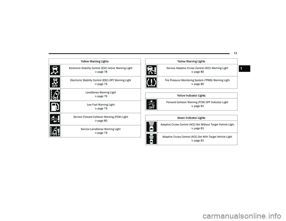
Electronic Stability Control (ESC) Active Warning Light Úpage 78
Electronic Stability Control (ESC) OFF Warning Light Úpage 79
LaneSense Warning Light Úpage 79
Low Fuel Warning Light Úpage 79
Service Forward Collision Warning (FCW) Light Úpage 80
Service LaneSense Warning Light Úpage 79
Yellow Warning Lights
Service Adaptive Cruise Control (ACC) Warning Light
Úpage 80
Tire Pressure Monitoring System (TPMS) Warning Light Úpage 80
Yellow Indicator Lights
Forward Collision Warning (FCW) OFF Indicator Light
Úpage 81
Green Indicator Lights
Adaptive Cruise Control (ACC) Set Without Target Vehicle Light
Úpage 81
Adaptive Cruise Control (ACC) Set With Target Vehicle Light Úpage 81
Yellow Warning Lights
1
22_LD_OM_EN_USC_t.book Page 11
Page 20 of 312
18GETTING TO KNOW YOUR VEHICLE
HOW TO USE REMOTE START
Push and release the Remote Start button on the
key fob twice within five seconds. The vehicle
doors will lock, the parking lights will flash, and the
horn will chirp twice (if programmed). Then, the
engine will start, and the vehicle will remain in the
Remote Start mode for a 15 minute cycle. Pushing
the Remote Start button a third time shuts the
engine off.
To drive the vehicle, push the unlock button, and
with a valid Keyless Enter ‘n Go™ key fob in the
vehicle, press the brake pedal and place the
ignition in the ON/RUN position.
NOTE:
With Remote Start, the engine will only run for
15 minutes.
Remote Start can only be used twice.
If an engine fault is present or fuel level is low,
the vehicle will start and then shut down in 10
seconds.
The parking lights will turn on and remain on
during Remote Start mode.
For security, power window operation is
disabled when the vehicle is in the Remote Start
mode.
The ignition must be placed in the ON/RUN posi -
tion before the Remote Start sequence can be
repeated for a third cycle.
All of the following conditions must be met before
the engine will remote start:
Gear selector in PARK
Doors closed
Hood closed
Trunk closed
Hazard switch off
Brake switch inactive (brake pedal not pressed)
Battery at an acceptable charge level
Check engine light shall not be present
PANIC button not pushed
System not disabled from previous Remote
Start event
Vehicle Security system indicator flashing
Ignition in the OFF position
Fuel level meets minimum requirement
Vehicle Security system is not signaling an intrusion
Malfunction Indicator Light (MIL) is not illumi -
nated
TO EXIT REMOTE START MODE
To drive the vehicle after starting the Remote Start
system, either push and release the unlock button
on the key fob to unlock the doors, or unlock the
vehicle using Keyless Enter ‘n Go™ — Passive Entry
via the door handles, and disarm the Vehicle
WARNING!
Do not start or run an engine in a closed
garage or confined area. Exhaust gas contains
Carbon Monoxide (CO) which is odorless and
colorless. Carbon Monoxide is poisonous and
can cause serious injury or death when
inhaled.
Keep key fobs away from children. Operation
of the Remote Start system, windows, door
locks or other controls could cause serious
injury or death.
22_LD_OM_EN_USC_t.book Page 18
Page 22 of 312
20GETTING TO KNOW YOUR VEHICLE
REMOTE START WINDSHIELD WIPER
D
E–ICER ACTIVATION — IF EQUIPPED
When Remote Start is active and the outside
ambient temperature is less than 33°F (0.6°C),
the Windshield Wiper De-Icer will activate. Exiting
Remote Start will resume its previous operation. If
the Windshield Wiper De-Icer was active, the timer
and operation will continue.
REMOTE START CANCEL MESSAGE —
I
F EQUIPPED
The following messages will display in the
instrument cluster display if the vehicle fails to
remote start or exits Remote Start prematurely:
Remote Start Cancelled — Door Open
Remote Start Cancelled — Hood Open
Remote Start Cancelled — Fuel Low
Remote Start Cancelled — Trunk Open
Remote Start Disabled — Start Vehicle To Reset
The instrument cluster display message stays
active until the ignition is placed in the ON/RUN
position.
VEHICLE SECURITY SYSTEM — IF EQUIPPED
The Vehicle Security system monitors the vehicle
doors, hood, trunk, and the Keyless Enter ‘n Go™
Ignition for unauthorized operation. While the
Vehicle Security system is armed, interior switches
for door locks and trunk release are disabled. If
something triggers the alarm, the Vehicle Security
system will provide the following audible and
visible signals:
The horn will pulse
The turn signals will flash
The Vehicle Security Light in the instrument
cluster will flash
TO ARM THE SYSTEM
Follow these steps to arm the Vehicle Security
system:
1. Make sure the vehicle’s ignition is placed in the OFF position.
2. Perform one of the following methods to lock the vehicle:
Push lock on the interior power door lock
switch with the driver and/or passenger
door open.
Push the lock button on the exterior Passive
Entry door handle with a valid key fob avail -
able in the same exterior zone Ú page 24.
Push the lock button on the key fob.
3. If any doors are open, close them.
TO DISARM THE SYSTEM
The Vehicle Security system can be disarmed using
any of the following methods:
Push the unlock button on the key fob.
Grab the Passive Entry door handle to unlock
the door Ú page 24.
Cycle the ignition out of the OFF position to
disarm the system.
NOTE:
The driver's door key cylinder and the trunk
button on the key fob cannot arm or disarm the
Vehicle Security system. Use of the door key
cylinder when the system is armed will sound
the alarm when the door is opened.
If Passive Entry (if equipped) is used to unlock
the trunk, the Vehicle Security system is
disarmed and the rest of the vehicle doors will
remain locked unless all doors are set to unlock
on first press within Uconnect Settings.
When the Vehicle Security system is armed, the
interior power door lock switches will not unlock
the doors.
22_LD_OM_EN_USC_t.book Page 20
Page 71 of 312
GETTING TO KNOW YOUR INSTRUMENT PANEL69
INSTRUMENT CLUSTER DESCRIPTIONS
1. Tachometer
Indicates the engine speed in revolutions
per minute (RPM x 1000).
2. Instrument Cluster Display
When the appropriate conditions exist, this
display shows the instrument cluster
display messages Ú page 69.
3. Speedometer
Indicates vehicle speed.
4. Temperature Gauge
The temperature gauge shows engine
coolant temperature. Any reading within the
normal range indicates that the engine
cooling system is operating satisfactorily.
The gauge pointer will likely indicate a
higher temperature when driving in hot
weather, up mountain grades, or when
towing a trailer. It should not be allowed to
exceed the upper limits of the normal oper -
ating range. 5. Fuel Gauge
The pointer shows the level of fuel in the
fuel tank when the Keyless Push Button
Ignition is in the ON/RUN position.
The fuel pump symbol points to
the side of the vehicle where the
fuel door is located.
NOTE:The hard telltales will illuminate for a bulb check
when the ignition is first cycled.
INSTRUMENT CLUSTER DISPLAY
Your vehicle is equipped with an instrument cluster
display, which offers useful information to the
driver. With the ignition in the OFF mode, opening/
closing of a door will activate the display for
viewing, and display the total miles, or kilometers,
in the odometer. Your instrument cluster display is
designed to display important information about
your vehicle’s systems and features. Using a driver
interactive display located on the instrument
panel, your instrument cluster display can show
you how systems are working and give you
warnings when they are not. The steering wheel
mounted controls allow you to scroll through the
main menus and submenus. You can access the
specific information you want and make selections
and adjustments.
WARNING!
A hot engine cooling system is dangerous. You or
others could be badly burned by steam or boiling
coolant. You may want to call an authorized
dealer for service if your vehicle overheats. If you
decide to look under the hood yourself, follow
the warnings under Cooling System Úpage 248.
CAUTION!
Driving with a hot engine cooling system could
damage your vehicle. If the temperature gauge
reads “H” pull over and stop the vehicle. Idle the
vehicle with the air conditioner turned off until
the pointer drops back into the normal range. If
the pointer remains on the “H”, turn the engine
off immediately and call an authorized dealer for
service.
3
22_LD_OM_EN_USC_t.book Page 69
Page 72 of 312
70GETTING TO KNOW YOUR INSTRUMENT PANEL
LOCATION AND CONTROLS
The instrument cluster display features an
interactive display which is located in the
instrument cluster.
Instrument Cluster Display Location And Controls
This system conveniently allows the driver to select
a variety of useful information by pushing the
arrow buttons located on the left side of the
steering wheel. The instrument cluster display
menu items consist of the following:
Speedometer
Vehicle Info
Performance — If Equipped
Driver Assist — If Equipped
Fuel Economy
Trip
Audio
Messages
Screen Setup
The system allows the driver to select information
by pushing the following buttons mounted on the
steering wheel:
Instrument Cluster Display Controls
Up And Down Arrow Buttons:
Using the
up or down arrow button allows
you to cycle through the Main Menu Items.
Changes the Main Screen area and Menu Title
area.
Left And Right Arrow Buttons:
Using the left or right arrow button allows
you to cycle through the submenu items of the
Main menu item.
NOTE:
Holding the up or down or left or
right arrow button will continuously loop
through the currently selected menu or options
presented on the screen.
Upon returning to a main menu, the last
submenu screen viewed within that main menu
will be displayed.
OK Button:
For Digital Speedometer:
Pushing the OK button changes units (mph or
km/h).
For Screen Setup:
OK button allows user to enter menu and
submenus.
1 – Instrument Cluster Display Screen
2 – Instrument Cluster Display Controls
1 — Left Arrow Button
2 — Up Arrow Button
3 — Right Arrow Button
4 — Down Arrow Button
5 — OK Button
22_LD_OM_EN_USC_t.book Page 70
Page 74 of 312
72GETTING TO KNOW YOUR INSTRUMENT PANEL
INSTRUMENT CLUSTER DISPLAY
S
ELECTABLE MENU ITEMS
Push and release the up or down arrow
button until the desired Selectable Menu item is
displayed in the instrument cluster display.
Follow the Menu or submenu prompts as desired.
Speedometer
Push and release the up or down arrow
button until the speedometer menu is displayed in
the instrument cluster display. Push and release
the OK button to toggle units (km/h or mph) of the
speedometer.
Vehicle Info
Push and release the up or down arrow
button until the “Vehicle Info” menu is displayed in
the instrument cluster display. Push and release
the right or left arrow button to scroll
through the submenus items of “Vehicle Info.”
Follow the directional prompts to access or reset
any of the following “Vehicle Info” submenu items:
Tire Pressure Monitor
Coolant Temperature
Trans Temperature
Oil Temperature
Oil Pressure
Oil Life
Battery Voltage
Intake Air Temperature — If Equipped
Engine Torque — If Equipped
Engine Power — If Equipped
Air-Fuel Ratio — If Equipped
Driver Assist — If Equipped
The Driver Assist menu displays the status of the
ACC and LaneSense systems.
Push and release the up or down arrow
button until the Driver Assist menu is displayed in
the instrument cluster display.
Adaptive Cruise Control (ACC) Feature
The instrument cluster displays the current ACC
system settings. The information displayed
depends on ACC system status.
Push the ACC on/off button (located on the
steering wheel) until one of the following displays
in the instrument cluster display:
Adaptive Cruise Control Off
When ACC is deactivated, the display will read
“Adaptive Cruise Control Off.”
Adaptive Cruise Control Ready
When ACC is activated but the vehicle speed
setting has not been selected, the display will read
“Adaptive Cruise Control Ready.” Push the SET + or the SET- button (located on the
steering wheel) and the following will display in the
instrument cluster display:
ACC SET
When ACC is set, the set speed will display in the
instrument cluster.
The ACC screen may display once again if any ACC
activity occurs, which may include any of the
following:Distance Setting Change
System Cancel
Driver Override
System Off
ACC Proximity Warning
ACC Unavailable Warning
The instrument cluster display will return to the last
display selected after five seconds of no ACC
display activity Ú page 96.
LaneSense — If Equipped
The instrument cluster displays the current
LaneSense system settings. The information
displayed depends on LaneSense system status
and the conditions that need to be met
Ú page 109.
22_LD_OM_EN_USC_t.book Page 72
Page 75 of 312
GETTING TO KNOW YOUR INSTRUMENT PANEL73
Fuel Economy
Two submenu pages; one with Current Value
(instantaneous calculation of the fuel economy)
displayed and one without the Current Value
displayed (toggle the left or right arrow
button to select one):
Current Fuel Economy (MPG, L/100 km, or km/L).
Range To Empty (miles or km).
Average Fuel Economy (MPG, L/100 km, or km/L).
The Max and Min values will correspond to the
particular engine requirements.
Lower end of gauge will be displayed in an
amber color and turn green as Fuel Economy
improves.
Hold the OK button to reset average fuel
economy information.
Trip Info
Push and release the up or down arrow
button until the Trip Menu item is displayed in the
instrument cluster display. Toggle the left or
right arrow button to select Trip A or Trip B. The
Trip information will display the following:
Distance – Shows the total distance (mi or km)
traveled for Trip A or Trip B since the last reset.
Average Fuel Economy – Shows the average
fuel economy (MPG, L/100km or km/L) of Trip A
or Trip B since the last reset.
Elapsed Time – Shows the total elapsed time of
travel since the last reset.
Hold the OK button to reset feature information.
Audio
This menu displays the Audio information of the
currently playing audio source (e.g. FM radio).
Messages
This feature shows the number of stored warning
messages, if any. Pushing the right or left
arrow button will allow you to scroll through the
stored messages.
Screen Setup
Push and release the up or down arrow
button until the Screen Setup Menu displays in the
instrument cluster display. Push and release the
OK button to enter the submenus. The Screen
Setup feature allows you to change what
information is displayed in the instrument cluster
as well as the location that information is
displayed.
Upper Left or Upper Right
None Compass Outside
Temperature
Time Range Avg L/100 km
(MPG or km/L)
Current L/
100 km (MPG
or km/L) Trip A Trip B
Trailer Trip Gain
Center
Digital
Speedometer CompassOutside
Temperature
Time Range to
EmptyAvg L/100 km
(MPG or km/L)
Current L/
100 km (MPG
or km/L) Trip A Trip B
Audio Menu Title
3
22_LD_OM_EN_USC_t.book Page 73