fuel DODGE CHARGER SRT 2007 6.G Owner's Manual
[x] Cancel search | Manufacturer: DODGE, Model Year: 2007, Model line: CHARGER SRT, Model: DODGE CHARGER SRT 2007 6.GPages: 350, PDF Size: 5.51 MB
Page 243 of 350
Loose Fuel Filler Cap Message
If the vehicle diagnostic system determines that the fuel
filler cap is loose, improperly installed, or damaged, a
ªCheck Gascapº message will display in the Electronic
Vehicle Information Center (EVIC). If this occurs, tighten
the fuel filler cap properly and press the odometer reset
button to turn off the message. If the problem continues,
the message will appear the next time the vehicle is
started.
A loose, improperly installed, or damaged fuel filler cap
may also turn on the Malfunction Indicator Light (MIL).
Refer to ªOnboard Diagnostic Systemº in Section 7 of this
manual for more information.
VEHICLE LOADING
The load carrying capacity of your vehicle is shown on
the ªVehicle Certification Label.º This information
should be used for passenger and luggage loading as
indicated.
If the seatbacks are folded for carrying cargo, do not
exceed the specified GVWR and GAWR.
Vehicle Certification Label
Your vehicle has a certification label attached to the rear
of the driver's door.
The label contains the following information:
²Name of manufacturer
²Month and year of manufacture
²Gross Vehicle Weight Rating (GVWR)
²Gross Axle Weight Rating (GAWR) front
²Gross Axle Weight Rating (GAWR) rear
²Vehicle Identification Number (VIN)
²Type of Vehicle
STARTING AND OPERATING 243
5
Page 254 of 350
²Do not operate the electric air pump for more than
eight minutes to avoid overheating. The air pump may
be used again once it has cooled down.
²Replace the TIREFIT sealant bottle (5) once every four
years to assure optimum operation of the system.
²If TIREFIT is liquid, clean water and a damp cloth will
remove the material from the vehicle or tire and wheel
components. Once TIREFIT sealing material has dried,
it can easily be peeled off and properly discarded.
²Do not exceed 55 mph (90 km/h) until the tire has
been inspected.
JUMP-STARTING PROCEDURES
WARNING!
²Take care to avoid the radiator cooling fan whenever the
hood is raised. It can start anytime the ignition switch is on.
You can be hurt by the fan.
²Do not attempt to push or tow your vehicle to get it started.
Vehicles equipped with an automatic transmission cannot
be started this way. Unburned fuel could enter the catalytic
converter and once the engine has started, ignite and
damage the converter and vehicle. If the vehicle has a
discharged battery, booster cables may be used to obtain a
start from another vehicle. This type of start can be danger-
ous if done improperly, so follow this procedure carefully.
²Battery fluid is a corrosive acid solution; do not allow
battery fluid to contact eyes, skin, or clothing. Don't lean
over battery when attaching clamps or allow the clamps to
touch each other. If acid splashes in eyes or on skin, flush
contaminated area immediately with large quantities of
water.
²A battery generates hydrogen gas, which is flammable and
explosive. Keep flame or spark away from the vent holes.
²Do not use a booster battery or any other booster source
with an output that exceeds 12 volts.
²The battery in this vehicle has a vent hose that should not
be disconnected and should only be replaced with a battery
of the same type (vented).
254 WHAT TO DO IN EMERGENCIES
Page 261 of 350
MAINTAINING YOUR VEHICLE
CONTENTS
m6.1L Engine Compartment...............263
mOnboard Diagnostic System Ð OBD II......264
NLoose Fuel Filler Cap..................264
mEmissions Inspection And Maintenance
Programs
............................265
mReplacement Parts.....................266
mDealer Service........................266
mMaintenance Procedures.................267
NEngine Oil..........................267
NEngine Oil Filter......................270
NDrive Belts Ð Check Condition And Tension . . 270
NSpark Plugs.........................270NEngine Air Cleaner Filter................271
NFuel Filter..........................271
NCatalytic Converter....................271
NMaintenance-Free Battery................273
NAir Conditioner Maintenance.............274
NA/C Air Filter Ð If Equipped............275
NPower Steering Ð Fluid Check............276
NFront & Rear Suspension Ball Joints........276
NSteering Linkage......................276
NBody Lubrication.....................276
NWindshield Wiper Blades................277
7
Page 262 of 350
NWindshield Washers...................277
NExhaust System......................278
NCooling System.......................278
NHoses And Vacuum/Vapor Harnesses.......283
NFuel System.........................283
NBrake System........................284
NAutomatic Transmission................286
NFront And Rear Wheel Bearings...........287
NAppearance Care And Protection From
Corrosion...........................287
NCleaning The Center Console Cup Holders . . . 291
mFuses (Power Distribution Centers).........291
NFuses (Front Power Distribution Center).....291
NFuses (Rear Power Distribution Center)......293
mVehicle Storage........................297
mReplacement Light Bulbs................298
mBulb Replacement......................299
NLow Beam Headlight, High Beam
Headlight, Park/Turn Light, And Front Side
Marker Light........................299
NBackup Light, Side Marker Light, Tail/Turn
Light, And Tail/Stop Light...............301
NLicense Light........................304
mFluids And Capacities...................304
mFluids, Lubricants, And Genuine Parts......305
NEngine.............................305
NChassis............................306
262 MAINTAINING YOUR VEHICLE
Page 264 of 350
ONBOARD DIAGNOSTIC SYSTEM Ð OBD II
Your vehicle is equipped with a sophisticated onboard
diagnostic system called OBD II. This system monitors
the performance of the emissions, engine, and automatic
transmission control systems. When these systems are
operating properly, your vehicle will provide excellent
performance and fuel economy, as well as engine emis-
sions well within current government regulations.
If any of these systems require service, the OBD II system
will turn on the ªMalfunction Indicator Light.º It will
also store diagnostic codes and other information to
assist your service technician in making repairs. Al-
though your vehicle will usually be drivable and not
need towing, see your dealer for service as soon as
possible.CAUTION!
Prolonged driving with the ªMalfunction Indicator
Lightº on could cause further damage to the emis-
sion control system. It could also affect fuel economy
and driveability. The vehicle must be serviced before
any emissions tests can be performed.
If the ªMalfunction Indicator Lightº is flashing
while the engine is running, severe catalytic con-
verter damage and power loss will soon occur. Im-
mediate service is required.
Loose Fuel Filler Cap
If the vehicle diagnostic system determines that the fuel
filler cap is loose, improperly installed, or damaged, a
ªCheck Gascapº message will display in the Electronic
Vehicle Information Center (EVIC) Ð if equipped. If this
occurs, tighten the fuel filler cap properly and press the
odometer reset button to turn off the message. If the
problem continues, the message will appear the next time
the vehicle is started.
264 MAINTAINING YOUR VEHICLE
Page 265 of 350
A loose, improperly installed, or damaged fuel filler cap
may also turn on the Malfunction Indicator Light (MIL).
EMISSIONS INSPECTION AND MAINTENANCE
PROGRAMS
In some localities, it may be a legal requirement to pass
an inspection of your vehicle's emissions control system.
Failure to pass could prevent vehicle registration.
For states, which have an I/M (Inspection and
Maintenance) requirement, this check verifies the
following: the MIL (Malfunction Indicator Lamp)
is functioning and is not on when the engine is running,
and that the OBD (On Board Diagnostic) system is ready
for testing.
Normally, the OBD system will be ready. The OBD
system maynotbe ready if your vehicle was recently
serviced, if you recently had a dead battery, or a battery
replacement. If the OBD system should be determined
not ready for the I/M test, your vehicle may fail the test.Your vehicle has a simple ignition key actuated test,
which you can use prior to going to the test station. To
check if your vehicle's OBD system is ready, you must do
the following:
1. Insert your ignition key into the ignition switch.
2. Turn the ignition to the ON position, but do not crank
or start the engine.
3. If you crank or start the engine, you will have to start
this test over.
4. As soon as you turn your key to the ON position, you
will see your MIL symbol come on as part of a normal
bulb check.
5. Approximately 15 seconds later, one of two things will
happen:
a. The MIL will flash for about 10 seconds and then
return to being fully illuminated until you turn off
the ignition key or start the engine. This means that
your vehicle's OBD system isnot readyand you
shouldnotproceed to the I/M station.
MAINTAINING YOUR VEHICLE 265
7
Page 267 of 350
WARNING!
You can be badly injured working on or around a
motor vehicle. Only do service work for which you
have the knowledge and the proper equipment. If
you have any doubt about your ability to perform a
service job, take your vehicle to a competent me-
chanic.
MAINTENANCE PROCEDURES
The pages that follow contain therequiredmaintenance
services determined by the engineers who designed your
vehicle.
Besides the maintenance items for which there are fixed
maintenance intervals, there are other items that should
operate satisfactorily without periodic maintenance.
However, if a malfunction of these items does occur, it
could adversely affect the engine or vehicle performance.
These items should be inspected if a malfunction is
observed or suspected.
Engine Oil
Checking Oil Level
To assure proper engine lubrication, the engine oil must
be maintained at the correct level. Check the oil level at
regular intervals, such as every fuel stop.
The best time to check the engine oil level is about 5
minutes after a fully warmed engine is shut off or before
starting the engine after it has sat overnight.
Checking the oil while the vehicle is on level ground will
improve the accuracy of the oil level readings. Maintain
the oil level in the ªSAFEº range. Adding 1.0 quart (1.0L)
of oil when the reading is at the bottom of the ªSAFEº
range will result in an oil level at the top of the ªSAFEº
range on these engines.
MAINTAINING YOUR VEHICLE 267
7
Page 271 of 350
Engine Air Cleaner Filter
For normal driving conditions, inspect and replace the
engine air cleaner filter at the intervals shown on Sched-
ule ªA.º For vehicles driven frequently in dusty or under
severe conditions, inspect and replace the engine air
cleaner filter at the intervals shown on Schedule ªB.º
WARNING!
The air induction system (air cleaner, hoses, etc) can
provide a measure of protection in the case of engine
backfire. Do not remove the air induction system (air
cleaner, hoses, etc) unless such removal is necessary
for repair or maintenance. Make sure that no one is
near the engine compartment before starting the
vehicle with the air induction system (air cleaner,
hoses, etc) removed. Failure to do so can result in
serious personal injury.
Fuel Filter
A plugged fuel filter can cause stalling, limit the speed at
which a vehicle can be driven or cause hard starting.
Should an excessive amount of dirt accumulate in the
fuel tank, filter replacement may be necessary. See your
authorized dealer for service.
Catalytic Converter
The catalytic converter requires the use of unleaded fuel
only. Leaded gasoline will destroy the effectiveness of the
catalyst as an emission control device.
Under normal operating conditions, the catalytic con-
verter will not require maintenance. However, it is im-
portant to keep the engine properly tuned to assure
proper catalyst operation and prevent possible catalyst
damage.
MAINTAINING YOUR VEHICLE 271
7
Page 283 of 350
²Make sure that the radiator and coolant recovery
bottle overflow hoses are not kinked or obstructed.
²Keep the front of the radiator clean. If your vehicle is
equipped with air conditioning, keep the front of the
condenser clean, also.
²Do not change the thermostat for summer or winter
operation. If replacement is ever necessary, install
ONLY the correct type thermostat. Other designs may
result in unsatisfactory coolant performance, poor gas
mileage, and increased emissions.
Hoses And Vacuum/Vapor Harnesses
Inspect surfaces of hoses and nylon tubing for evidence
of heat and mechanical damage. Hard or soft spots,
brittle rubber, cracking, tears, cuts, abrasions, and exces-
sive swelling indicate deterioration of the rubber.
Pay particular attention to those hoses nearest to high
heat sources such as the exhaust manifold. Inspect hose
routing to be sure hoses do not come in contact with any
heat source or moving component which may cause heat
damage or mechanical wear.Insure nylon tubing in these areas has not melted or
collapsed.
Inspect all hose connections such as clamps and cou-
plings to make sure they are secure and no leaks are
present.
Components should be replaced immediately if there is
any evidence of wear or damage that could cause failure.
Fuel System
The Electronic Fuel Injection high-pressure fuel system's
hoses and quick connect fittings have unique material
characteristics that provide adequate sealing and resist
attack by deteriorated gasoline.
You are urged to use only the manufacture specified
hoses with quick connect fittings, or their equivalent in
material and specification, in any fuel system servicing. It
is mandatory to replace any damaged hoses or quick
connect fittings that have been removed during service.
Care should be taken in installing quick connect fittings
to insure they are properly installed and fully connected.
See your authorized dealer for service.
MAINTAINING YOUR VEHICLE 283
7
Page 294 of 350
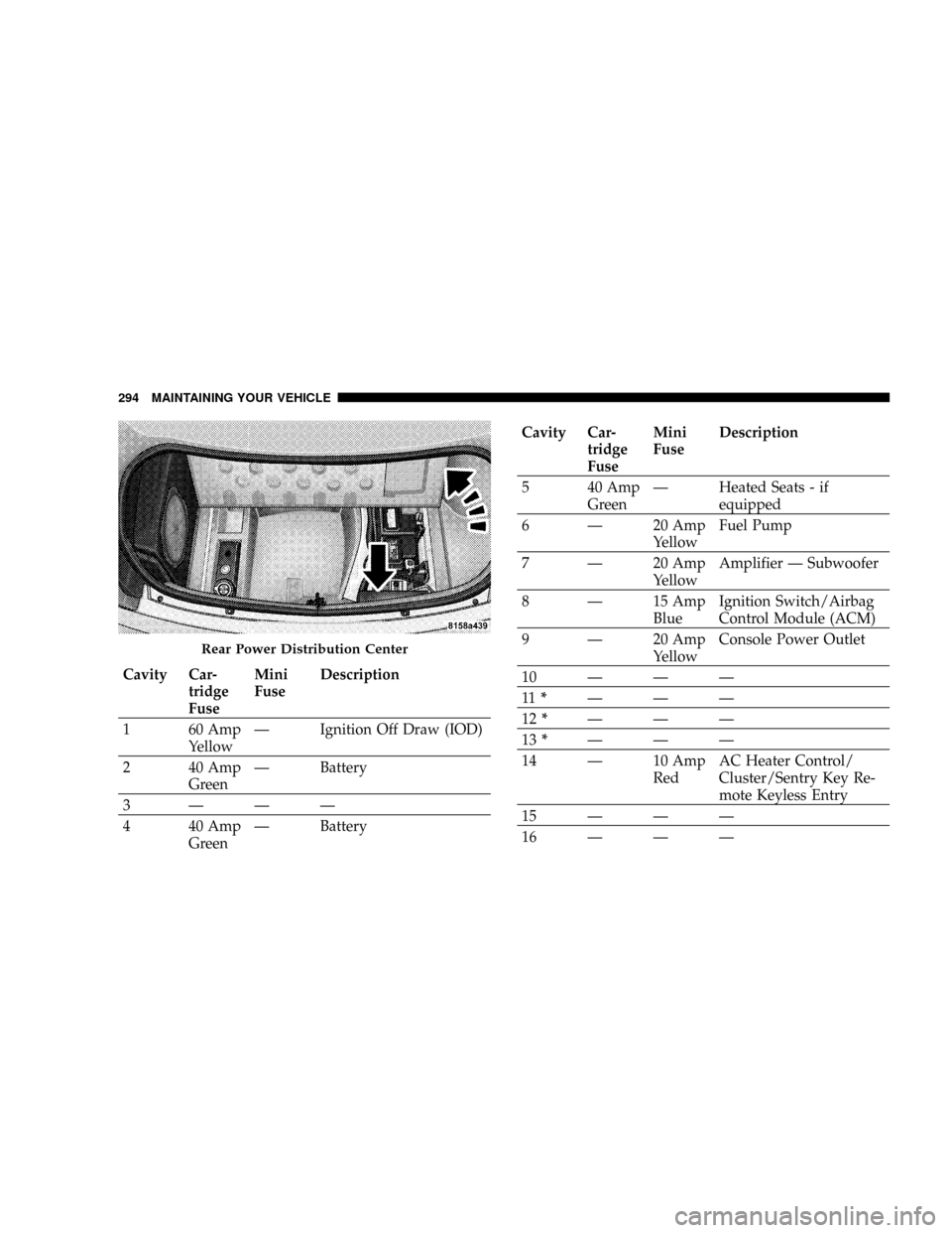
Cavity Car-
tridge
FuseMini
FuseDescription
1 60 Amp
YellowÐ Ignition Off Draw (IOD)
2 40 Amp
GreenÐ Battery
3ÐÐÐ
4 40 Amp
GreenÐ Battery
Cavity Car-
tridge
FuseMini
FuseDescription
5 40 Amp
GreenÐ Heated Seats - if
equipped
6 Ð 20 Amp
YellowFuel Pump
7 Ð 20 Amp
YellowAmplifier Ð Subwoofer
8 Ð 15 Amp
BlueIgnition Switch/Airbag
Control Module (ACM)
9 Ð 20 Amp
YellowConsole Power Outlet
10ÐÐÐ
11*ÐÐÐ
12*ÐÐÐ
13*ÐÐÐ
14 Ð 10 Amp
RedAC Heater Control/
Cluster/Sentry Key Re-
mote Keyless Entry
15ÐÐÐ
16ÐÐÐ
Rear Power Distribution Center
294 MAINTAINING YOUR VEHICLE