parking brake DODGE CHARGER SRT 2015 7.G Owners Manual
[x] Cancel search | Manufacturer: DODGE, Model Year: 2015, Model line: CHARGER SRT, Model: DODGE CHARGER SRT 2015 7.GPages: 595, PDF Size: 16.43 MB
Page 17 of 595
you to cycle the ignition to OFF. In addition to the chime,
the ignition or accessory on message will display in the
cluster.
NOTE:With the Uconnect® system, the power window
switches, radio, power sunroof (if equipped), and power
outlets will remain active for up to 10 minutes after the
ignition is placed in the OFF position. Opening either
front door will cancel this feature. The time for this
feature is programmable. Refer to “Uconnect® Settings”
in “Understanding Your Instrument Panel” for further
information.
WARNING!
•When leaving the vehicle, always remove the Key
Fob from the vehicle and lock your vehicle.
•Never leave children alone in a vehicle, or with
access to an unlocked vehicle.
(Continued)
WARNING!(Continued)
•Allowing children to be in a vehicle unattended is
dangerous for a number of reasons. A child or
others could be seriously or fatally injured. Chil-
dren should be warned not to touch the parking
brake, brake pedal or the gear selector.
•Do not leave the Key Fob in or near the vehicle, or
in a location accessible to children, and do not
leave the ignition of a vehicle equipped with
Keyless Enter-N-Go™ in the ACC or ON/RUN
mode. A child could operate power windows, other
controls, or move the vehicle.
•Do not leave children or animals inside parked
vehicles in hot weather. Interior heat build-up may
cause serious injury or death.
2
THINGS TO KNOW BEFORE STARTING YOUR VEHICLE 15
Page 29 of 595
How To Use Remote Start
All of the following conditions must be met before the
engine will remote start:
•Shift lever in PARK
•Doors closed
•Hood closed
•Hazard switch off
•Brake switch inactive (brake pedal not pushed)
•Battery at an acceptable charge level
•RKE PANIC button not pushed
•System not disabled from previous remote start event
•Vehicle security alarm not active
•Ignition in Off position (Keyless Enter-N-Go™)
WARNING!
•Do not start or run an engine in a closed garage or
confined area. Exhaust gas contains Carbon Mon-
oxide (CO) which is odorless and colorless. Carbon
Monoxide is poisonous and can cause serious in-
jury or death when inhaled.
•Keep Remote Keyless Entry (RKE) transmitters
away from children. Operation of the Remote Start
System, windows, door locks or other controls
could cause serious injury or death.
To Enter Remote Start Mode
Push and release the REMOTE START button on
the RKE transmitter twice within five seconds.
The vehicle doors will lock, the parking lights
will flash, and horn will chirp twice (if pro-
grammed). Then, the engine will start and the vehicle will
remain in the Remote Start mode for a 15-minute cycle.
2
THINGS TO KNOW BEFORE STARTING YOUR VEHICLE 27
Page 32 of 595
If the door lock knob is down when you shut the door,
the door will lock. Therefore, make sure the Key Fob is
not inside the vehicle before closing the door.
WARNING!
•For personal security and safety in the event of a
collision, lock the vehicle doors before you drive as
well as when you park and leave the vehicle.
•When leaving the vehicle, always make sure the
keyless ignition node is in the “OFF” mode, re-
move the Key Fob from the vehicle and lock your
vehicle.
(Continued)
WARNING!(Continued)
•Never leave children alone in a vehicle, or with
access to an unlocked vehicle. Allowing children to
be in a vehicle unattended is dangerous for a
number of reasons. A child or others could be
seriously or fatally injured. Children should be
warned not to touch the parking brake, brake pedal
or the gear selector.
•Do not leave the Key Fob in or near the vehicle, or
in a location accessible to children, and do not
leave the ignition of a vehicle equipped with
Keyless Enter-N-Go™ in the ACC or ON/RUN
mode. A child could operate power windows, other
controls, or move the vehicle.
30 THINGS TO KNOW BEFORE STARTING YOUR VEHICLE
Page 102 of 595
Periodic Safety Checks You Should Make Outside
The Vehicle
Tires
Examine tires for excessive tread wear and uneven wear
patterns. Check for stones, nails, glass, or other objects
lodged in the tread or sidewall. Inspect the tread for cuts
and cracks. Inspect sidewalls for cuts, cracks, and bulges.
Check the wheel nuts for tightness. Check the tires
(including spare) for proper cold inflation pressure.
Lights
Have someone observe the operation of brake lights and
exterior lights while you work the controls. Check turn
signal and high beam indicator lights on the instrument
panel.
Door Latches
Check for proper closing, latching, and locking.
Fluid Leaks
Check area under vehicle after overnight parking for fuel,
engine coolant, oil, or other fluid leaks. Also, if gasoline
fumes are detected or if fuel, power steering fluid (if
equipped), or brake fluid leaks are suspected, the cause
should be located and corrected immediately.
100 THINGS TO KNOW BEFORE STARTING YOUR VEHICLE
Page 151 of 595
Daytime Running Lights (DRL) — If Equipped
The Daytime Running Lights will turn On when the
engine is started and remain On unless the headlamps
are turned ON, the parking brake is applied, or the
engine is shut Off.
NOTE:If allowed by law in the country in which the
vehicle was purchased the Daytime Running Lights can
be turned on and off using the Uconnect® System, refer
to “Uconnect® Settings” in “Understanding Your Instru-
ment Panel” for further information.
Lights-On Reminder
If the headlights or parking lights are on after the ignition
is placed in the OFF position, a chime will sound to alert
the driver when the driver’s door is opened.
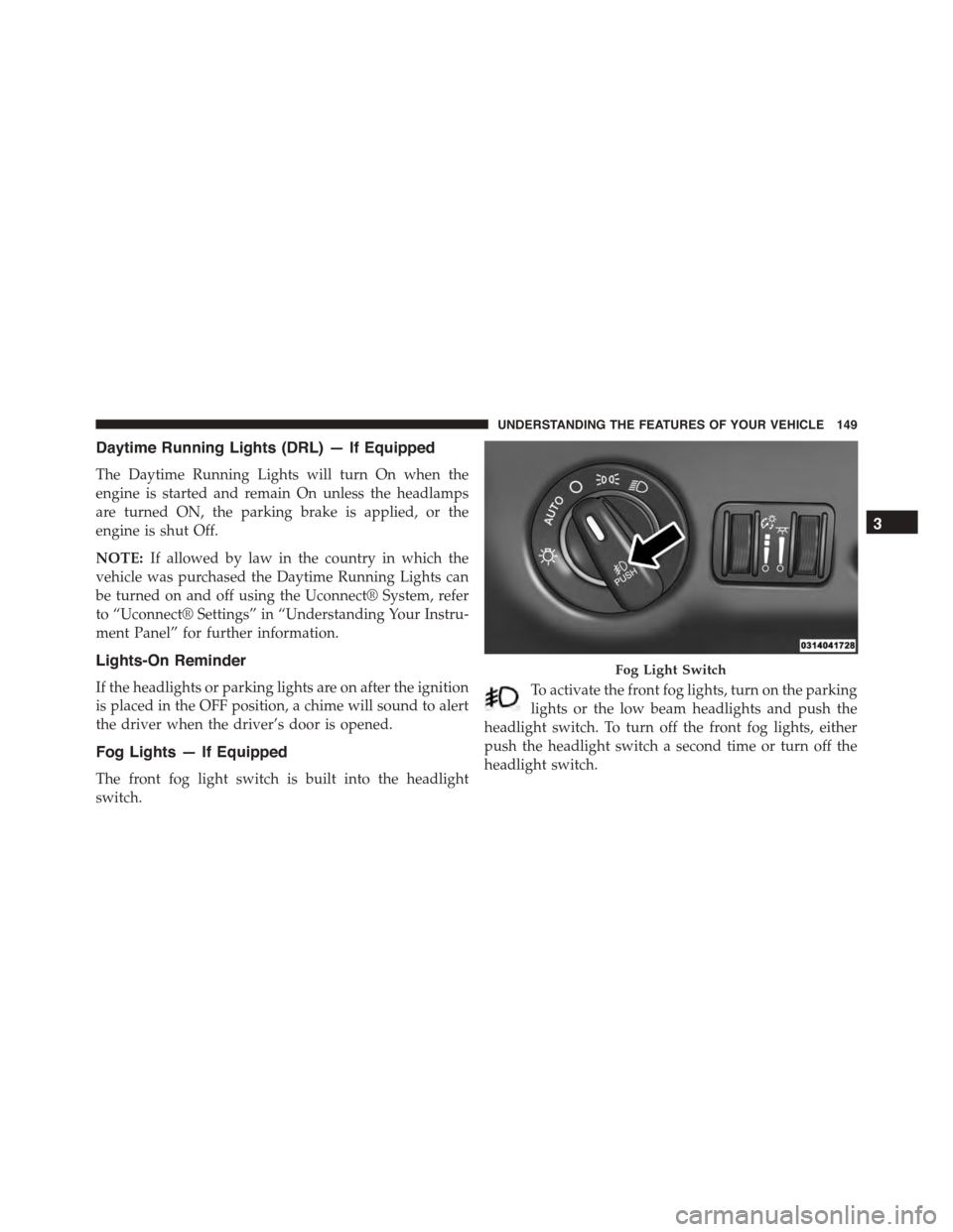
Fog Lights — If Equipped
The front fog light switch is built into the headlight
switch.
To activate the front fog lights, turn on the parking
lights or the low beam headlights and push the
headlight switch. To turn off the front fog lights, either
push the headlight switch a second time or turn off the
headlight switch.
Fog Light Switch
3
UNDERSTANDING THE FEATURES OF YOUR VEHICLE 149
Page 175 of 595
NOTE:Any chassis/suspension or tire size modifications
to the vehicle will effect the performance of the Adaptive
Cruise Control and Forward Collision Warning System.
Activating Adaptive Cruise Control (ACC)
You can only engage ACC if the vehicle speed is above
0 mph (0 km/h).
The minimum Set Speed for the ACC system is 20 mph
(32 km/h).
When the system is turned on and in the READY state,
the Driver Information Display (DID) displays “ACC
Ready.”
When the system is OFF, the DID displays “Adaptive
Cruise Control (ACC) Off.”
NOTE:You cannot engage ACC under the following
conditions:
•When you apply the brakes.
•When the parking brake is set.
•When the automatic transmission is in PARK, RE-
VERSE or NEUTRAL.
•When the Vehicle speed is outside of the speed range.
•When the brakes are overheated.
•When the driver door is open.
•When the driver seat belt is unbuckled.
3
UNDERSTANDING THE FEATURES OF YOUR VEHICLE 173
Page 178 of 595
•The shift lever/gear selector is removed from the
Drive position.
•The Electronic Stability Control/Traction Control Sys-
tem (ESC/TCS) activates.
•The vehicle parking brake is applied.
•Driver seatbelt is unbuckled at low speeds.
•Driver door is opened at low speeds.
•The driver switches ESC to full-off mode.
NOTE:
•If your vehicle stays at standstill for longer than two
seconds, then the system will cancel and the brake
force will be ramped-out. The driver will have to apply
the brakes to keep the vehicle at a standstill.
•ACC cannot be resumed if there is a stationary vehicle
in-front of your vehicle in close proximity.
To Turn Off
The system will turn off and erase the set speed in
memory if:
•The Normal (Fixed Speed) Electronic Speed Control
ON/OFF button is pushed.
•The ignition is turned off.
•The Adaptive Cruise Control (ACC) On/Off button is
pushed.
To Resume
If there is a set speed in memory push the RES (resume)
button and then remove your foot from the accelerator
pedal. The DID will display the last set speed.
176 UNDERSTANDING THE FEATURES OF YOUR VEHICLE
Page 197 of 595
The drivers preferred units can be selected through the
instrument panel settings if equipped. Refer to “Under-
standing Your Instrument Panel” for more information.
The speed decrement shown is dependant on the speed
of U.S. (mph) or Metric (km/h) units:
U.S. Speed (mph)
•Pushing the SET-button once will result ina1mph
decrease in set speed. Each subsequent tap of the
button results in a decrease of 1 mph.
•If the button is continually pushed, the set speed will
continue to decrease in 5 mph decrements until the
button is released. The decrease in set speed is re-
flected in the DID display.
Metric Speed (km/h)
•Pushing the SET-button once will result in a 1 km/h
decrease in set speed. Each subsequent tap of the
button results in a decrease of 1 km/h.
•If the button is continually pushed, the set speed will
continue to decrease in 10 km/h decrements until the
button is released. The decrease in set speed is re-
flected in the DID display.
To Cancel
The following conditions will cancel the Normal (Fixed
Speed) Electronic Speed Control without clearing the
memory:
•The brake pedal is applied.
•The CANCEL button is pushed.
•The Electronic Stability Control/Traction Control Sys-
tem (ESC/TCS) activates.
•The vehicle parking brake is applied.
•The braking temperature exceeds normal range (over-
heated).
3
UNDERSTANDING THE FEATURES OF YOUR VEHICLE 195
Page 208 of 595
NOTE:The LaneSense system operates with the similar
behavior for a right lane departure.
Changing LaneSense Status
The LaneSense system settings can be configured
through the Uconnect® system screen.
Follow these steps to change the LaneSense settings:
1. Push the “Controls” button on touchscreen located on
the bottom of the Uconnect® display.
2. Push the “Settings” button.
3. Push the “Safety & Driving Assistance” button.
When in the Safety & Driving Assistance screen, you can
configure the intensity of the torque warning and the
warning zone sensitivity (early/late) through the person-
alization settings.
NOTE:
•When enabled the system operates above 37 mph
(60 km/h) and below 112 mph (180 km/h).
•Use of the turn signal suppresses the warnings.
•The system will not apply torque to the steering wheel
whenever a safety system engages. (anti-lock brakes,
traction control system, electronic stability control,
forward collision warning, etc.)
PARKSENSE® REAR PARK ASSIST — IF
EQUIPPED
The ParkSense® Rear Park Assist system provides visual
and audible indications of the distance between the rear
fascia and a detected obstacle when backing up, e.g.
during a parking maneuver. Refer to “ParkSense® Sys-
tem Usage Precautions” in this section for limitations of
this system and recommendations.
206 UNDERSTANDING THE FEATURES OF YOUR VEHICLE
Page 253 of 595
INSTRUMENT CLUSTER DESCRIPTIONS
1. Tachometer
The red segments indicate the maximum permissible
engine revolutions per minute (RPM x 1000) for each gear
range. Ease up on the accelerator before reaching the red
area. The transition of the red line starts 500 RPM prior to
the actual redline. 6.2L SC redline = 6250 RPM and 6.4L
redline = 6400 RPM.
2. High Beam Indicator
This indicator will turn on when the high beam
headlights are on. Push the multifunction lever
away from the steering wheel to switch the headlights to
high beam.
3. Brake Warning Light
This light monitors various brake functions,
including brake fluid level and parking brake
application. If the brake light turns on, it may
indicate that the parking brake is applied, that
the brake fluid level is low, or that there is a problem with
the anti-lock brake system reservoir.
If the light remains on when the parking brake has been
disengaged, and the fluid level is at the full mark on the
master cylinder reservoir, it indicates a possible brake
hydraulic system malfunction. In this case, the light will
remain on until the condition has been corrected.
The dual brake system provides a reserve braking capac-
ity in the event of a failure to a portion of the hydraulic
system. A leak in either half of the dual brake system is
indicated by the Brake Warning Light which will turn on
when the brake fluid level in the master cylinder has
dropped below a specified level.
4
UNDERSTANDING YOUR INSTRUMENT PANEL 251