towing DODGE CHARGER SRT 2015 7.G Owners Manual
[x] Cancel search | Manufacturer: DODGE, Model Year: 2015, Model line: CHARGER SRT, Model: DODGE CHARGER SRT 2015 7.GPages: 595, PDF Size: 16.43 MB
Page 123 of 595
The BSM detection zone covers approximately one lane
width on both sides of the vehicle 12 ft (3.8 m). The zone
length starts at the outside rear view mirror and extends
approximately 10 ft (3 m) beyond the rear bumper of the
vehicle. The BSM system monitors the detection zones on
both sides of the vehicle when the vehicle speed reaches
approximately 6 mph (10 km/h) or higher and will alert
the driver of vehicles in these areas.
NOTE:
•The BSM system does NOT alert the driver about
rapidly approaching vehicles that are outside the de-
tection zones.
•The BSM system detection zone DOES NOT change if
your vehicle is towing a trailer. Therefore, visually
verify the adjacent lane is clear for both your vehicle
and trailer before making a lane change. If the trailer or
other object (i.e., bicycle, sports equipment) extends
beyond the side of your vehicle, this may result in the
BSM warning light remaining illuminated the entire
time the vehicle is in a forward gear.
The area on the rear fascia where the radar sensors are
located must remain free of snow, ice, and dirt/road
contamination so that the BSM system can function
properly. Do not block the area of the rear fascia where
the radar sensors are located with foreign objects (bum-
per stickers, bicycle racks, etc.).
The BSM system notifies the driver of objects in the
detection zones by illuminating the BSM warning light
located in the outside mirrors in addition to sounding an
audible (chime) alert and reducing the radio volume.
Refer to “Modes Of Operation” for further information.
The BSM system monitors the detection zone from three
different entry points (side, rear, front) while driving to
see if an alert is necessary. The BSM system will issue an
alert during these types of zone entries.
3
UNDERSTANDING THE FEATURES OF YOUR VEHICLE 121
Page 174 of 595
WARNING!(Continued)
•When towing a trailer up or down steep slopes.
•When circumstances do not allow safe driving at a
constant speed.
Adaptive Cruise Control (ACC) Operation
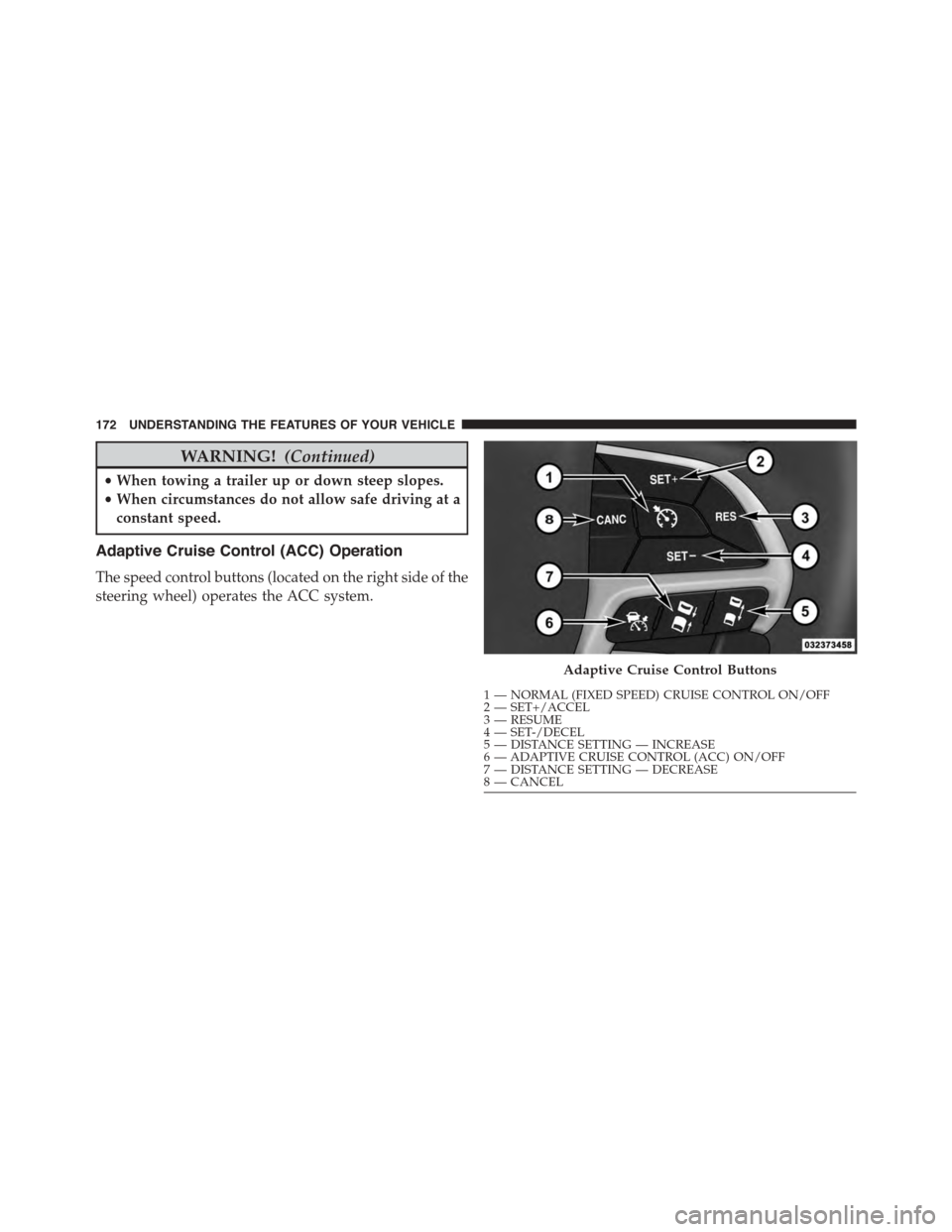
The speed control buttons (located on the right side of the
steering wheel) operates the ACC system.
Adaptive Cruise Control Buttons
1—NORMAL(FIXEDSPEED)CRUISECONTROLON/OFF2—SET+/ACCEL3—RESUME4—SET-/DECEL5—DISTANCESETTING—INCREASE6—ADAPTIVECRUISECONTROL(ACC)ON/OFF7—DISTANCESETTING—DECREASE8—CANCEL
172 UNDERSTANDING THE FEATURES OF YOUR VEHICLE
Page 190 of 595
When the condition that created limited functionality is
no longer present, the system will return to full function-
ality.
NOTE:If the “ACC/FCW Limited Functionality Clean
Front Windshield” message occurs frequently (e.g. more
than once on every trip) without any snow, rain, mud, or
other obstruction, have the windshield and forward
facing camera inspected at your authorized dealer.
Service ACC/FCW Warning
If the system turns off, and the DID displays “ACC/FCW
Unavailable Service Required” or “Cruise/FCW Unavail-
able Service Required”, there may be an internal system
fault or a temporary malfunction that limits ACC func-
tionality. Although the vehicle is still drivable under
normal conditions, ACC will be temporarily unavailable.
If this occurs, try activating ACC again later, following an
ignition cycle. If the problem persists, see your autho-
rized dealer.
Precautions While Driving With ACC
In certain driving situations, ACC may have detection
issues. In these cases, ACC may brake late or unexpect-
edly. The driver needs to stay alert and may need to
intervene.
Towing A Trailer
Towing a trailer is not advised when using ACC.
Offset Driving
ACC may not detect a vehicle in the same lane that is
offset from your direct line of travel, or a vehicle merging
in from a side lane. There may not be sufficient distance
to the vehicle ahead. The offset vehicle may move in and
out of the line of travel, which can cause your vehicle to
brake or accelerate unexpectedly.
188 UNDERSTANDING THE FEATURES OF YOUR VEHICLE
Page 260 of 595
The gauge pointer will likely indicate a higher tempera-
ture when driving in hot weather, up mountain grades,
or when towing a trailer. It should not be allowed to
exceed the upper limits of the normal operating range.
CAUTION!
Driving with a hot engine cooling system could
damage your vehicle. If the temperature gauge reads
“H,” pull over and stop the vehicle. Idle the vehicle
with the air conditioner turned off until the pointer
drops back into the normal range. If the pointer
remains on the “H,” and you hear a chime, turn the
engine OFF immediately and call for service.
WARNING!
A hot engine cooling system is dangerous. You or
others could be badly burned by steam or boiling
coolant. You may want to call a service center if your
vehicle overheats. If you decide to look under the
hood yourself, refer to “Maintaining Your Vehicle”
and follow the warnings under the Cooling System
Pressure Cap paragraph.
16. Seat Belt Reminder Light
This light will turn on for four to eight seconds as
a bulb check when the ignition is first placed in
ON/RUN position. A chime will sound if the
driver’s seat belt is unbuckled during the bulb check. The
Seat Belt Warning Light will flash or remain on continu-
ously if the driver’s seat belt remains unbuckled after the
bulb check or when driving. Refer to “Occupant Re-
straints” in “Things To Know Before Starting Your Ve-
hicle” for further information.
258 UNDERSTANDING YOUR INSTRUMENT PANEL
Page 261 of 595
17. Vehicle Security Light — If Equipped
This light will flash at a fast rate for approxi-
mately 15 seconds when the vehicle security
alarm is arming, and then will flash slowly
until the vehicle is disarmed.
18. Malfunction Indicator Light (MIL)
The Malfunction Indicator Light (MIL) is part of
an onboard diagnostic system called OBD. The
OBD system monitors engine and automatic
transmission control systems. The MIL will turn on when
the ignition is in the ON/RUN position before engine
start. If the MIL does not come on when turning the key
from OFF to ON/RUN, have the condition checked
promptly.
Certain conditions, such as a loose or missing gas cap,
poor fuel quality, etc., may illuminate the MIL after
engine start. The vehicle should be serviced if the MIL
stays on through several of your typical driving cycles. In
most situations, the vehicle will drive normally and will
not require towing.
CAUTION!
Prolonged driving with the Malfunction Indicator
Light (MIL) on could cause damage to the engine
control system. It also could affect fuel economy and
driveability. If the MIL is flashing, severe catalytic
converter damage and power loss will soon occur.
Immediate service is required.
4
UNDERSTANDING YOUR INSTRUMENT PANEL 259
Page 270 of 595
•Electronic Throttle Control (ETC) Light
This light informs you of a problem with the
Electronic Throttle Control (ETC) system. The
light will come on when the ignition is first
turned ON and remain on briefly as a bulb
check. If the light does not come on during starting, have
the system checked by an authorized dealer.
If a problem is detected, the light will come on while the
engine is running. Cycle the ignition key when the
vehicle has completely stopped and the shift lever is
placed in the PARK position. The light should turn off.
If the light remains lit with the engine running, your
vehicle will usually be drivable. However, see an autho-
rized dealer for service as soon as possible. If the light is
flashing when the engine is running, immediate service is
required. You may experience reduced performance, an
elevated/rough idle or engine stall, and your vehicle
may require towing.
•Oil Temperature Warning Light
This telltale indicates engine oil temperature is
high. If the light turns on while driving, stop
the vehicle and shut off the engine as soon as
possible.
•Air Bag Warning Light
This light will turn on for four to eight seconds
as a bulb check when the ignition switch is first
turned to the ON/RUN position. If the light is
either not on during starting, stays on, or turns
on while driving, have the system inspected at an autho-
rized dealer as soon as possible. Refer to “Occupant
Restraints” in “Things To Know Before Starting Your
Vehicle” for further information.
268 UNDERSTANDING YOUR INSTRUMENT PANEL
Page 271 of 595
•Speed Limit Warning Light
Push and release the UP or DOWN arrow
button until the Speed Limit Warning Menu
icon/title is highlighted in the DID. Push and
release OK to enter speed warning. Use UP or
DOWN arrow to select a desired speed, then push and
release OK to set the speed. The Manual Speed Assist
(MSA) Speed Warning telltale will display in the DID,
and a chime will sound with a pop up warning message
when the set speed is exceeded.
•Transmission Temperature Warning Light
This light indicates that there is excessive trans-
mission fluid temperature that might occur
with severe usage such as trailer towing. It may
also occur when operating the vehicle in a high
torque converter slip condition. If this light comes on,
stop the vehicle and run the engine at idle or faster with
the transmission in NEUTRAL until the light goes off.
CAUTION!
Continuous driving with the Transmission Tempera-
ture Warning Light illuminated will eventually cause
severe transmission damage or transmission failure.
WARNING!
If you continue operating the vehicle when the
Transmission Temperature Warning Light is illumi-
nated you could cause the fluid to boil over, come in
contact with hot engine or exhaust components and
cause a fire.
4
UNDERSTANDING YOUR INSTRUMENT PANEL 269
Page 370 of 595
▫MMT In Gasoline.....................452
▫Materials Added To Fuel................453
▫Fuel System Cautions...................453
▫Carbon Monoxide Warnings.............454
!ADDING FUEL........................455
▫Emergency Fuel Filler Door Release.........457
!VEHICLE LOADING....................458
▫Vehicle Certification Label...............459
▫Gross Vehicle Weight Rating (GVWR).......459
▫Gross Axle Weight Rating (GAWR).........459
▫Overloading.........................460
▫Loading............................460
!TRAILER TOWING.....................461
!RECREATIONAL TOWING (BEHIND
MOTORHOME, ETC.)...................461
368 STARTING AND OPERATING
Page 384 of 595
WARNING!
Do not coast in NEUTRAL and never turn off the
ignition to coast down a hill. These are unsafe
practices that limit your response to changing traffic
or road conditions. You might lose control of the
vehicle and have a collision.
CAUTION!
Towing the vehicle, coasting, or driving for any other
reason with the transmission in NEUTRAL can cause
severe transmission damage. Refer to “Recreational
Towing” in “Starting And Operating” and “Towing A
Disabled Vehicle” in “What To Do In Emergencies”
for further information.
DRIVE (D)
This range should be used for most city and highway
driving. It provides the smoothest upshifts and down-
shifts, and the best fuel economy. The transmission
automatically upshifts through all forward gears. The
DRIVE position provides optimum driving characteris-
tics under all normal operating conditions.
When frequent transmission shifting occurs (such as
when operating the vehicle under heavy loading condi-
tions, in hilly terrain or traveling into strong head winds),
use the AutoStick shift control (refer to#AutoStick#in this
section for further information) to select a lower gear.
Under these conditions, using a lower gear will improve
performance and extend transmission life by reducing
excessive shifting and heat buildup.
382 STARTING AND OPERATING
Page 417 of 595
Towing With HSA
HSA will provide assistance when starting on a grade
when pulling a trailer.
WARNING!
•HSA is not a parking brake. Always apply the
parking brake fully when leaving your vehicle.
Also, be certain to leave the transmission in PARK.
•Failure to follow these warnings may cause the
vehicle to roll down the incline and could collide
with another vehicle, object or person, and cause
serious or fatal injury. Always remember to use the
parking brake while parking on a hill and that the
driver is responsible for braking the vehicle.
HSA Off
If you wish to turn off the HSA system, it can be done in
the Uconnect® settings. Refer to#Uconnect® Settings#in
#Understanding Your Instrument Panel#for further infor-
mation.
Ready Alert Braking
Ready Alert Braking may reduce the time required to
reach full braking during emergency braking situations.
It anticipates when an emergency braking situation may
occur by monitoring how fast the throttle is released by
the driver. When the throttle is released very quickly,
Ready Alert Braking applies a small amount of brake
pressure. This brake pressure will not be noticed by the
driver. The brake system uses this brake pressure to allow
a fast brake response if the driver applies the brakes.
5
STARTING AND OPERATING 415