warning lights DODGE CHARGER SRT 2015 7.G Owners Manual
[x] Cancel search | Manufacturer: DODGE, Model Year: 2015, Model line: CHARGER SRT, Model: DODGE CHARGER SRT 2015 7.GPages: 595, PDF Size: 16.43 MB
Page 29 of 595
How To Use Remote Start
All of the following conditions must be met before the
engine will remote start:
ŌĆóShift lever in PARK
ŌĆóDoors closed
ŌĆóHood closed
ŌĆóHazard switch off
ŌĆóBrake switch inactive (brake pedal not pushed)
ŌĆóBattery at an acceptable charge level
ŌĆóRKE PANIC button not pushed
ŌĆóSystem not disabled from previous remote start event
ŌĆóVehicle security alarm not active
ŌĆóIgnition in Off position (Keyless Enter-N-GoŌäó)
WARNING!
ŌĆóDo not start or run an engine in a closed garage or
confined area. Exhaust gas contains Carbon Mon-
oxide (CO) which is odorless and colorless. Carbon
Monoxide is poisonous and can cause serious in-
jury or death when inhaled.
ŌĆóKeep Remote Keyless Entry (RKE) transmitters
away from children. Operation of the Remote Start
System, windows, door locks or other controls
could cause serious injury or death.
To Enter Remote Start Mode
Push and release the REMOTE START button on
the RKE transmitter twice within five seconds.
The vehicle doors will lock, the parking lights
will flash, and horn will chirp twice (if pro-
grammed). Then, the engine will start and the vehicle will
remain in the Remote Start mode for a 15-minute cycle.
2
THINGS TO KNOW BEFORE STARTING YOUR VEHICLE 27
Page 31 of 595
NOTE:For vehicles equipped with the Keyless Enter-N-
GoŌäó feature, the message ŌĆ£Push Button/Insert KeyŌĆØ will
display in the Driver Information Display (DID) until
you push the START button.
Cancel Remote Start
Remote Starting will also cancel if any of the following
occur:
ŌĆóThe engine stalls or engine speed exceeds 2500 rpm.
ŌĆóAny engine warning lights come on.
ŌĆóLow Fuel Light turns on.
ŌĆóThe hood is opened.
ŌĆóThe hazard switch is pushed.
ŌĆóThe shift lever is moved out of PARK.
ŌĆóThe brake pedal is pushed.
DOOR LOCKS
Manual Door Locks
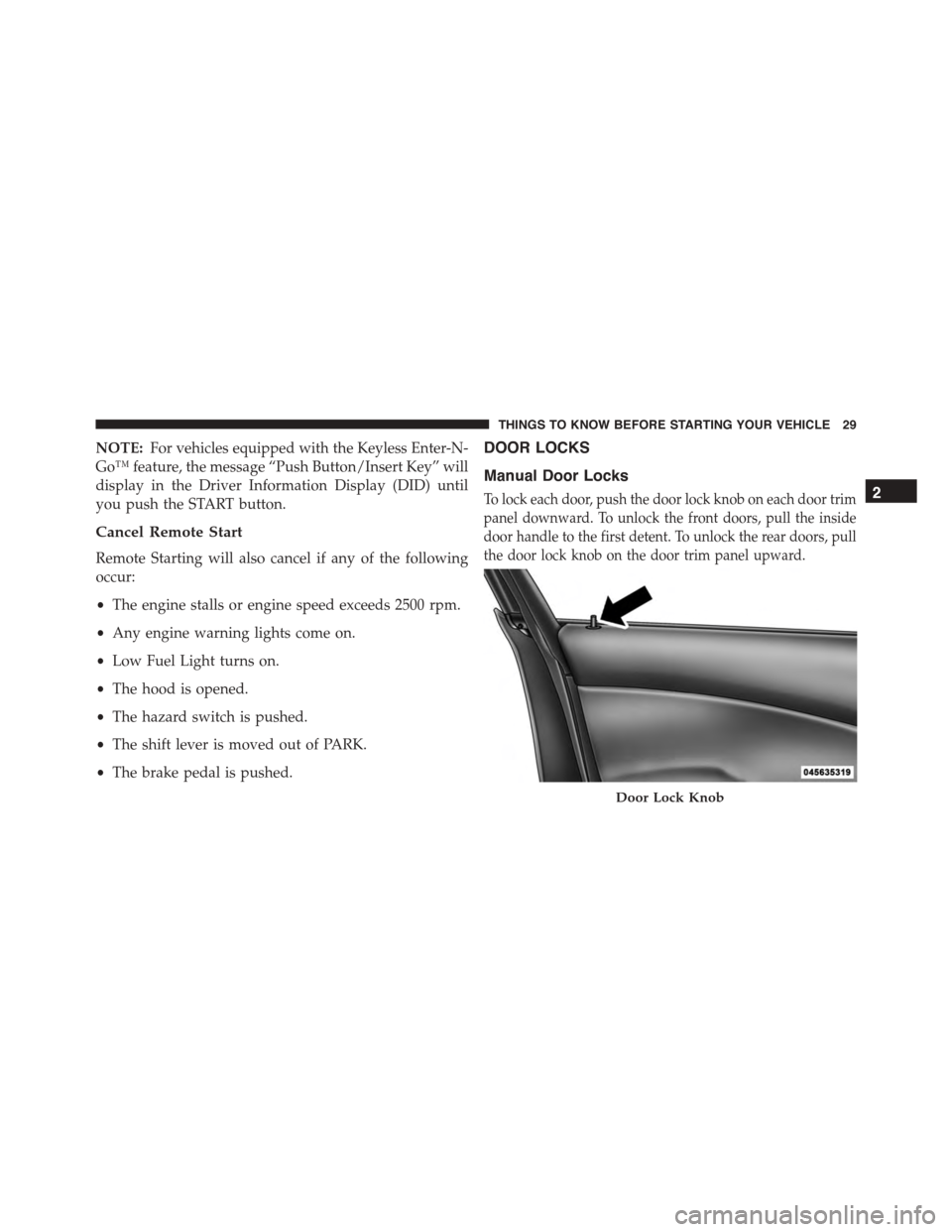
To lock each door, push the door lock knob on each door trim
panel downward. To unlock the front doors, pull the inside
door handle to the first detent. To unlock the rear doors, pull
the door lock knob on the door trim panel upward.
Door Lock Knob
2
THINGS TO KNOW BEFORE STARTING YOUR VEHICLE 29
Page 63 of 595
On the other hand, depending on the type and location of
impact, Advanced Front Air Bags may deploy in crashes
with little vehicle front-end damage but that produce a
severe initial deceleration.
Because air bag sensors measure vehicle deceleration
over time, vehicle speed and damage by themselves are
not good indicators of whether or not an air bag should
have deployed.
Seat belts are necessary for your protection in all colli-
sions, and also are needed to help keep you in position,
away from an inflating air bag.
When the ORC detects a collision requiring the Ad-
vanced Front Air Bags, it signals the inflator units. A large
quantity of non-toxic gas is generated to inflate the
Advanced Front Air Bags.
The steering wheel hub trim cover and the upper right
side of the instrument panel separate and fold out of the
way as the air bags inflate to their full size. The Advanced
Front Air Bags fully inflate in less time than it takes to
blink your eyes. The air bags then quickly deflate while
helping to restrain the driver and front passenger.
Knee Impact Bolsters
The Knee Impact Bolsters help protect the knees of the
driver and front passenger, and position the front occu-
pants for improved interaction with the Advanced Front
Air Bags.
WARNING!
ŌĆóDo not drill, cut, or tamper with the knee impact
bolsters in any way.
ŌĆóDo not mount any accessories to the knee impact
bolsters such as alarm lights, stereos, citizen band
radios, etc.
2
THINGS TO KNOW BEFORE STARTING YOUR VEHICLE 61
Page 70 of 595
Do not drive your vehicle after the air bags have de-
ployed. If you are involved in another collision, the air
bags will not be in place to protect you.
WARNING!
Deployed air bags and seat belt pretensioners cannot
protect you in another collision. Have the air bags,
seat belt pretensioners, and the seat belt retractor
assemblies replaced by an authorized dealer imme-
diately. Also, have the Occupant Restraint Controller
System serviced as well.
NOTE:
ŌĆóAir bag covers may not be obvious in the interior trim,
but they will open during air bag deployment.
ŌĆóAfter any collision, the vehicle should be taken to an
authorized dealer immediately.
Enhanced Accident Response System
In the event of an impact, if the communication network
remains intact, and the power remains intact, depending
on the nature of the event, the ORC will determine
whether to have the Enhanced Accident Response Sys-
tem perform the following functions:
ŌĆóCut off fuel to the engine.
ŌĆóFlash hazard lights as long as the battery has power or
until the ignition is placed in the ŌĆ£OFFŌĆØ position.
ŌĆóTurn on the interior lights, which remain on as long as
the battery has power or until the ignition is placed in
the ŌĆ£OFFŌĆØ position.
ŌĆóUnlock the doors automatically.
68 THINGS TO KNOW BEFORE STARTING YOUR VEHICLE
Page 107 of 595
Ō¢½Changing FCW And Active Braking Status. . . .199
Ō¢½FCW Limited Warning..................200
Ō¢½Service FCW Warning..................200
!LANESENSE ŌĆö IF EQUIPPED.............201
Ō¢½LaneSense Operation...................201
Ō¢½Turning LaneSense ON Or OFF............202
Ō¢½LaneSense Warning Message..............202
Ō¢½Changing LaneSense Status..............206
!PARKSENSE┬« REAR PARK ASSIST ŌĆö IF
EQUIPPED...........................206
Ō¢½ParkSense┬« Sensors....................207
Ō¢½ParkSense┬« Warning Display.............207
Ō¢½ParkSense┬« Display....................207
Ō¢½Enabling And Disabling ParkSense┬«........213
Ō¢½Service The ParkSense┬« Rear Park Assist
System.............................214
Ō¢½Cleaning The ParkSense┬« System..........214
Ō¢½ParkSense┬« System Usage Precautions.......215
!PARKVIEW┬« REAR BACK UP CAMERA ŌĆö IF
EQUIPPED...........................216
!OVERHEAD CONSOLE..................219
Ō¢½Front Map/Reading Lights ŌĆö If Equipped . . .219
Ō¢½Courtesy Lights.......................220
Ō¢½Sunglasses Bin Door...................221
!GARAGE DOOR OPENER ŌĆö IF EQUIPPED . . .221
Ō¢½Before You Begin Programming HomeLink┬« . .222
Ō¢½Programming A Rolling Code.............223
3
UNDERSTANDING THE FEATURES OF YOUR VEHICLE 105
Page 128 of 595
NOTE:In a parking lot situation, oncoming vehicles can
be obscured by vehicles parked on either side. If the
sensors are blocked by other structures or vehicles, the
system will not be able to alert the driver.
When RCP is on and the vehicle is in REVERSE, the
driver is alerted using both the visual and audible
alarms, including reducing the radio volume.
WARNING!
RCP is not a Back Up Aid system. It is intended to be
used to help a driver detect an oncoming vehicle in a
parking lot situation. Drivers must be careful when
backing up, even when using RCP. Always check
carefully behind your vehicle, look behind you, and
be sure to check for pedestrians, animals, other
vehicles, obstructions, and blind spots before back-
ing up. Failure to do so can result in serious injury or
death.
Modes Of Operation
Three selectable modes of operation are available in the
Uconnect┬« System. Refer to ŌĆ£Uconnect┬« Settings/
Customer Programmable FeaturesŌĆØ in ŌĆ£Understanding
Your Instrument PanelŌĆØ for further information.
Blind Spot Alert Lights Only
When operating in Blind Spot Alert mode, the BSM
system will provide a visual alert in the appropriate side
view mirror based on a detected object. However, when
the system is operating in Rear Cross Path mode, the
system will respond with both visual and audible alerts
when a detected object is present. Whenever an audible
alert is requested, the radio volume is reduced.
Blind Spot Alert Lights/Chime
When operating in Blind Spot Alert Lights/Chime mode,
the BSM system will provide a visual alert in the appro-
priate side view mirror based on a detected object. If the
126 UNDERSTANDING THE FEATURES OF YOUR VEHICLE
Page 147 of 595
CAUTION!
To prevent possible damage, do not slam the hood to
close it. Lower the hood until it is open approxi-
mately 6 inches (15 cm), and then drop it. This should
secure both latches. Never drive your vehicle unless
the hood is fully closed, with both latches engaged.
WARNING!
Be sure the hood is fully latched before driving your
vehicle. If the hood is not fully latched, it could open
when the vehicle is in motion and block your vision.
Failure to follow this warning could result in serious
injury or death.
LIGHTS
Headlight Switch
The headlight switch is located on the left side of
the instrument panel. This switch controls the
operation of the headlights, parking lights, instru-
ment panel lights, instrument panel light dimming, inte-
rior lights and fog lights (if equipped).
3
UNDERSTANDING THE FEATURES OF YOUR VEHICLE 145
Page 184 of 595
To increase the distance setting, push the Distance Setting
ŌĆö Increase button and release. Each time the button is
pushed, the distance setting increases by one bar (longer).
To decrease the distance setting, push the Distance Set-
ting ŌĆö Decrease button and release. Each time the button
is pushed, the distance setting decreases by one bar
(shorter).
If there is no vehicle ahead, the vehicle will maintain the
set speed. If a slower moving vehicle is detected in the
same lane, the DID displays the ŌĆ£Sensed Vehicle Indica-
torŌĆØ icon, and the system adjusts vehicle speed automati-
cally to maintain the distance setting, regardless of the set
speed.
The vehicle will then maintain the set distance until:
ŌĆóThe vehicle ahead accelerates to a speed above the set
speed.
ŌĆóThe vehicle ahead moves out of your lane or view of
the sensor.
ŌĆóThe distance setting is changed.
ŌĆóThe system disengages. (Refer to the information on
ACC Activation).
The maximum braking applied by ACC is limited; how-
ever, the driver can always apply the brakes manually, if
necessary.
NOTE:The brake lights will illuminate whenever the
ACC system applies the brakes.
A Proximity Warning will alert the driver if ACC predicts
that its maximum braking level is not sufficient to
maintain the set distance. If this occurs, a visual alert
ŌĆ£BRAKEŌĆØ will flash in the DID and a chime will sound
while ACC continues to apply its maximum braking
capacity.
182 UNDERSTANDING THE FEATURES OF YOUR VEHICLE
Page 238 of 595
NOTE:The instrument panel power outlet and dual rear
console USB ports can be changed to ŌĆ£batteryŌĆØ powered
all the time by moving the #12 20 Amp fuse from ŌĆ£IGNŌĆØ
to ŌĆ£B+ŌĆØ. Refer to ŌĆ£Rear Power Distribution Center
CoverŌĆØ in ŌĆ£Rear Power Distribution Center (Fuses)ŌĆØ.
WARNING!
To avoid serious injury or death:
ŌĆóOnly devices designed for use in this type of outlet
should be inserted into any 12 Volt outlet.
ŌĆóDo not touch with wet hands.
ŌĆóClose the lid when not in use and while driving the
vehicle.
ŌĆóIf this outlet is mishandled, it may cause an electric
shock and failure.
CAUTION!
ŌĆóMany accessories that can be plugged in draw
power from the vehicleŌĆÖs battery even when not in
use (i.e., cellular phones, etc.). Eventually, if
plugged in long enough, the vehicleŌĆÖs battery will
discharge sufficiently to degrade battery life and/or
prevent the engine from starting.
ŌĆóAccessories that draw higher power (i.e., coolers,
vacuum cleaners, lights, etc.) will degrade the bat-
tery even more quickly. Only use these intermit-
tently and with greater caution.
ŌĆóAfter the use of high power draw accessories or
long periods of the vehicle not being started (with
accessories still plugged in), the vehicle must be
driven a sufficient length of time to allow the
alternator to recharge the vehicleŌĆÖs battery.
(Continued)
236 UNDERSTANDING THE FEATURES OF YOUR VEHICLE
Page 253 of 595
INSTRUMENT CLUSTER DESCRIPTIONS
1. Tachometer
The red segments indicate the maximum permissible
engine revolutions per minute (RPM x 1000) for each gear
range. Ease up on the accelerator before reaching the red
area. The transition of the red line starts 500 RPM prior to
the actual redline. 6.2L SC redline = 6250 RPM and 6.4L
redline = 6400 RPM.
2. High Beam Indicator
This indicator will turn on when the high beam
headlights are on. Push the multifunction lever
away from the steering wheel to switch the headlights to
high beam.
3. Brake Warning Light
This light monitors various brake functions,
including brake fluid level and parking brake
application. If the brake light turns on, it may
indicate that the parking brake is applied, that
the brake fluid level is low, or that there is a problem with
the anti-lock brake system reservoir.
If the light remains on when the parking brake has been
disengaged, and the fluid level is at the full mark on the
master cylinder reservoir, it indicates a possible brake
hydraulic system malfunction. In this case, the light will
remain on until the condition has been corrected.
The dual brake system provides a reserve braking capac-
ity in the event of a failure to a portion of the hydraulic
system. A leak in either half of the dual brake system is
indicated by the Brake Warning Light which will turn on
when the brake fluid level in the master cylinder has
dropped below a specified level.
4
UNDERSTANDING YOUR INSTRUMENT PANEL 251