DODGE CHARGER SRT 2018 Owners Manual
Manufacturer: DODGE, Model Year: 2018, Model line: CHARGER SRT, Model: DODGE CHARGER SRT 2018Pages: 490, PDF Size: 5.08 MB
Page 291 of 490
4. Squeeze the two tabs on the side of the bulb socket andpull straight out from the lamp assembly.
5. Disconnect the bulb from the wiring connector and install the replacement bulb.
6. Install the bulb and connector assembly straight into the lamp until it locks in place.
7. Install the turn signal bulb cap in the headlamp housing and rotate clockwise to lock in place.
Backup Lamps
The Backup Lamps use LED sources that are not service-
able separately. The Applique must be replaced as an
assembly; see your authorized dealer.
License Lamp
The License Lamp uses an LED source that is not service-
able separately. The License Lamp must be replaced as an
assembly; see your authorized dealer.
Center High Mounted Stop Lamp (CHMSL)
The CHMSL Lamp uses LED sources that are not service-
able separately. The CHMSL Lamp must be replaced as an
assembly; see your authorized dealer.
FUSES
WARNING!
•When replacing a blown fuse, always use an appro-
priate replacement fuse with the same amp rating as
the original fuse. Never replace a fuse with another
fuse of higher amp rating. Never replace a blown
fuse with metal wires or any other material. Do not
place a fuse inside a circuit breaker cavity or vice
versa. Failure to use proper fuses may result in
serious personal injury, fire and/or property damage.
• Before replacing a fuse, make sure that the ignition is
off and that all the other services are switched off
and/or disengaged.
• If the replaced fuse blows again, contact an autho-
rized dealer.
• If a general protection fuse for safety systems (air
bag system, braking system), power unit systems
(engine system, transmission system) or steering
system blows, contact an authorized dealer.
7
IN CASE OF EMERGENCY 289
Page 292 of 490
General Information
The fuses protect electrical systems against excessive current.
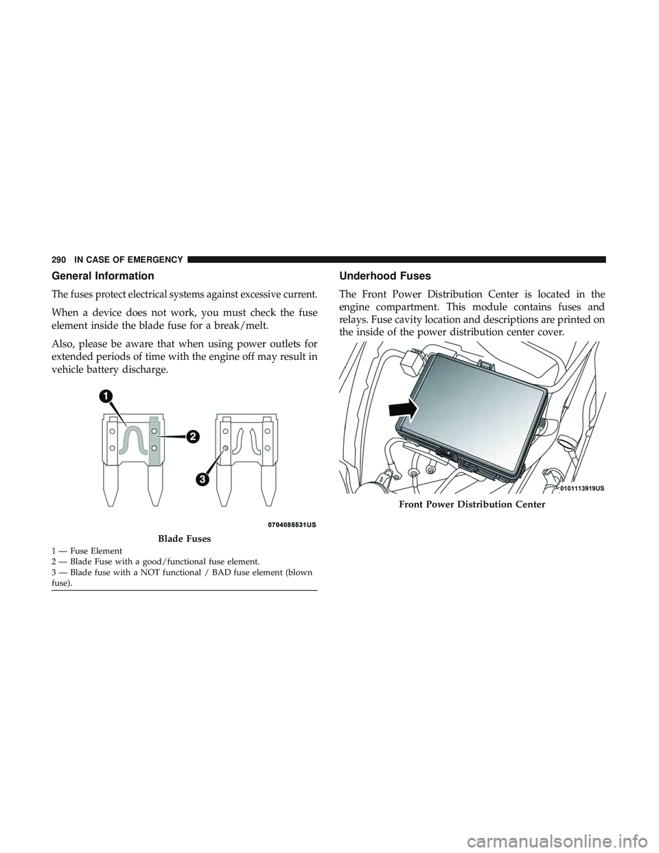
When a device does not work, you must check the fuse
element inside the blade fuse for a break/melt.
Also, please be aware that when using power outlets for
extended periods of time with the engine off may result in
vehicle battery discharge.
Underhood Fuses
The Front Power Distribution Center is located in the
engine compartment. This module contains fuses and
relays. Fuse cavity location and descriptions are printed on
the inside of the power distribution center cover.
Blade Fuses
1 — Fuse Element
2 — Blade Fuse with a good/functional fuse element.
3 — Blade fuse with a NOT functional / BAD fuse element (blown
fuse).
Front Power Distribution Center
290 IN CASE OF EMERGENCY
Page 293 of 490
CAUTION!
•When installing the power distribution center cover,
it is important to ensure the cover is properly posi-
tioned and fully latched. Failure to do so may allow
water to get into the power distribution center and
possibly result in an electrical system failure.
• When replacing a blown fuse, it is important to use
only a fuse having the correct amperage rating. The
use of a fuse with a rating other than indicated may
result in a dangerous electrical system overload. If a
properly rated fuse continues to blow, it indicates a
problem in the circuit that must be corrected.
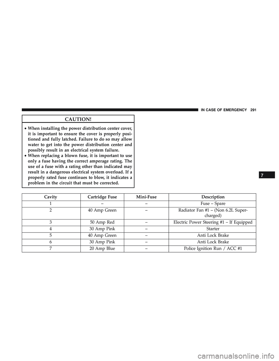
Cavity Cartridge Fuse Mini-Fuse Description
1 –– Fuse – Spare
2 40 Amp Green –Radiator Fan #1 – (Non 6.2L Super-
charged)
3 50 Amp Red –Electric Power Steering #1 – If Equipped
4 30 Amp Pink – Starter
5 40 Amp Green –Anti Lock Brake
6 30 Amp Pink –Anti Lock Brake
7 20 Amp Blue –Police Ignition Run / ACC #1
7
IN CASE OF EMERGENCY 291
Page 294 of 490
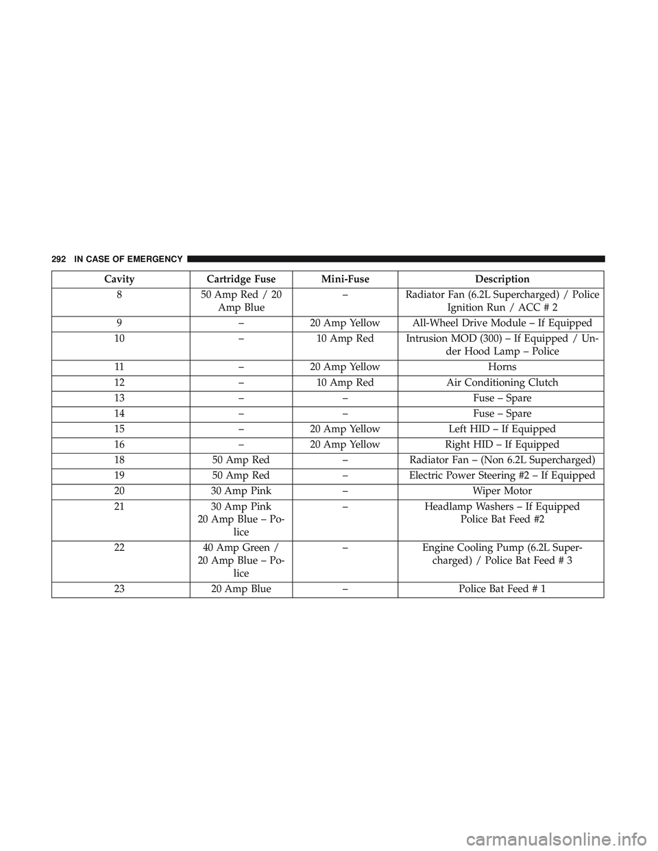
CavityCartridge Fuse Mini-Fuse Description
8 50 Amp Red / 20
Amp Blue –
Radiator Fan (6.2L Supercharged) / Police
Ignition Run / ACC # 2
9 –20 Amp Yellow All-Wheel Drive Module – If Equipped
10 –10 Amp Red Intrusion MOD (300) – If Equipped / Un-
der Hood Lamp – Police
11 –20 Amp Yellow Horns
12 –10 Amp Red Air Conditioning Clutch
13 –– Fuse – Spare
14 –– Fuse – Spare
15 –20 Amp Yellow Left HID – If Equipped
16 –20 Amp Yellow Right HID – If Equipped
18 50 Amp Red –Radiator Fan – (Non 6.2L Supercharged)
19 50 Amp Red –Electric Power Steering #2 – If Equipped
20 30 Amp Pink –Wiper Motor
21 30 Amp Pink
20 Amp Blue – Po- lice –
Headlamp Washers – If Equipped
Police Bat Feed #2
22 40 Amp Green /
20 Amp Blue – Po- lice –
Engine Cooling Pump (6.2L Super-
charged) / Police Bat Feed # 3
23 20 Amp Blue –Police Bat Feed # 1
292 IN CASE OF EMERGENCY
Page 295 of 490
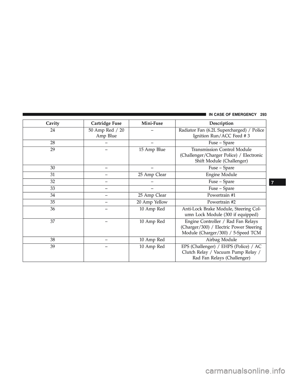
CavityCartridge Fuse Mini-Fuse Description
24 50 Amp Red / 20
Amp Blue –
Radiator Fan (6.2L Supercharged) / Police
Ignition Run/ACC Feed # 3
28 –– Fuse – Spare
29 –15 Amp Blue Transmission Control Module
(Challenger/Charger Police) / Electronic Shift Module (Challenger)
30 –– Fuse – Spare
31 –25 Amp Clear Engine Module
32 –– Fuse – Spare
33 –– Fuse – Spare
34 –25 Amp Clear Powertrain #1
35 –20 Amp Yellow Powertrain #2
36 –10 Amp Red Anti-Lock Brake Module, Steering Col-
umn Lock Module (300 if equipped)
37 –10 Amp Red Engine Controller / Rad Fan Relays
(Charger/300) / Electric Power SteeringModule (Charger/300) / 5-Speed TCM
38 –10 Amp Red Airbag Module
39 –10 Amp Red EPS (Challenger) / EHPS (Police) / AC
Clutch Relay / Vacuum Pump Relay /Rad Fan Relays (Challenger)
7
IN CASE OF EMERGENCY 293
Page 296 of 490
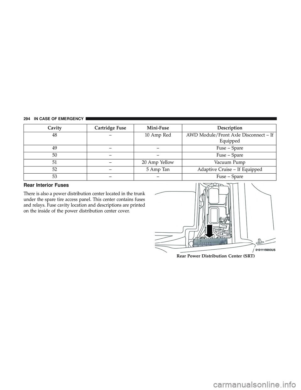
CavityCartridge Fuse Mini-Fuse Description
48 –10 Amp Red AWD Module/Front Axle Disconnect – If
Equipped
49 –– Fuse – Spare
50 –– Fuse – Spare
51 –20 Amp Yellow Vacuum Pump
52 –5 Amp Tan Adaptive Cruise – If Equipped
53 –– Fuse – Spare
Rear Interior Fuses
There is also a power distribution center located in the trunk
under the spare tire access panel. This center contains fuses
and relays. Fuse cavity location and descriptions are printed
on the inside of the power distribution center cover.
Rear Power Distribution Center (SRT)
294 IN CASE OF EMERGENCY
Page 297 of 490
CAUTION!
•When installing the power distribution center cover,
it is important to ensure the cover is properly posi-
tioned and fully latched. Failure to do so may allow
water to get into the power distribution center and
possibly result in an electrical system failure.
• When replacing a blown fuse, it is important to use
only a fuse having the correct amperage rating. The
use of a fuse with a rating other than indicated may
result in a dangerous electrical system overload. If a
properly rated fuse continues to blow, it indicates a
problem in the circuit that must be corrected.
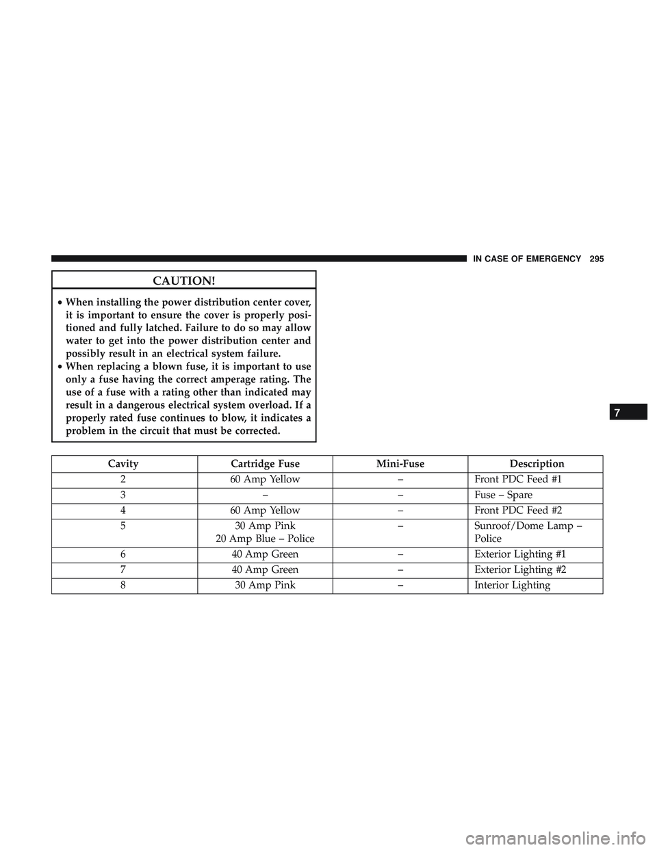
Cavity Cartridge Fuse Mini-FuseDescription
2 60 Amp Yellow –Front PDC Feed #1
3 ––Fuse – Spare
4 60 Amp Yellow –Front PDC Feed #2
5 30 Amp Pink
20 Amp Blue – Police –
Sunroof/Dome Lamp –
Police
6 40 Amp Green –Exterior Lighting #1
7 40 Amp Green –Exterior Lighting #2
8 30 Amp Pink –Interior Lighting
7
IN CASE OF EMERGENCY 295
Page 298 of 490
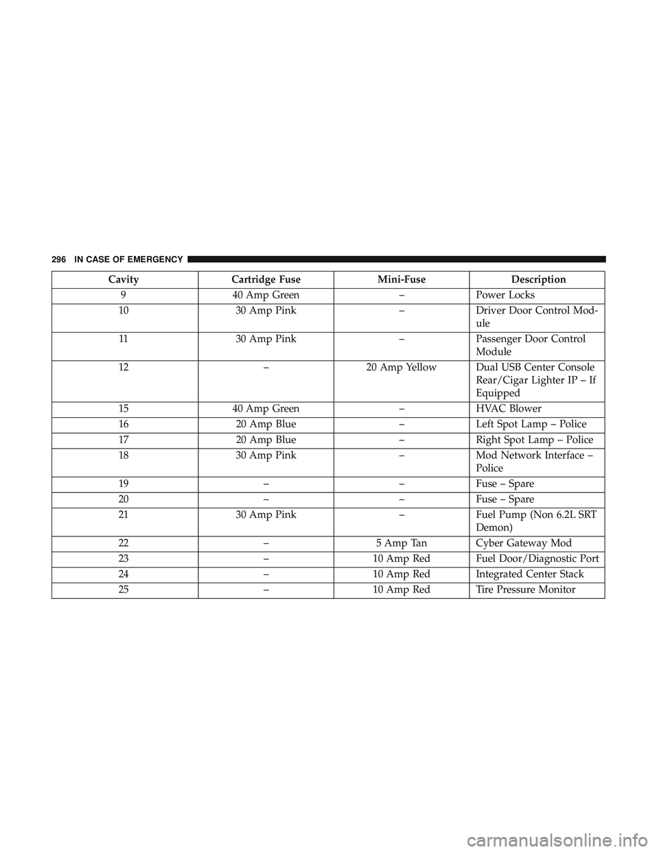
CavityCartridge Fuse Mini-FuseDescription
9 40 Amp Green –Power Locks
10 30 Amp Pink –Driver Door Control Mod-
ule
11 30 Amp Pink –Passenger Door Control
Module
12 –20 Amp Yellow Dual USB Center Console
Rear/Cigar Lighter IP – If
Equipped
15 40 Amp Green –HVAC Blower
16 20 Amp Blue –Left Spot Lamp – Police
17 20 Amp Blue –Right Spot Lamp – Police
18 30 Amp Pink –Mod Network Interface –
Police
19 ––Fuse – Spare
20 ––Fuse – Spare
21 30 Amp Pink –Fuel Pump (Non 6.2L SRT
Demon)
22 –5 Amp Tan Cyber Gateway Mod
23 –10 Amp Red Fuel Door/Diagnostic Port
24 –10 Amp Red Integrated Center Stack
25 –10 Amp Red Tire Pressure Monitor
296 IN CASE OF EMERGENCY
Page 299 of 490
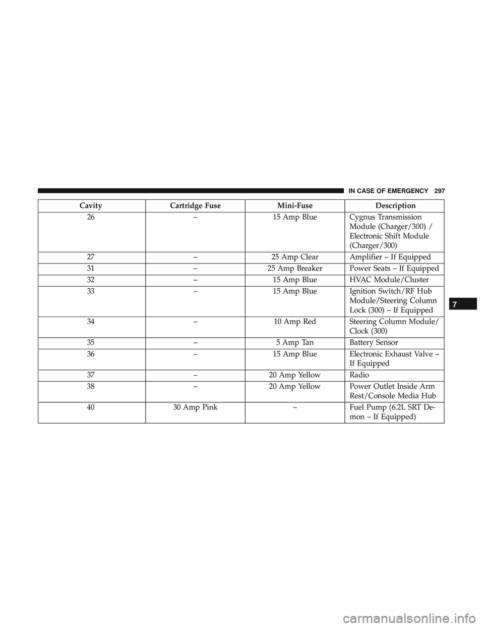
CavityCartridge Fuse Mini-FuseDescription
26 –15 Amp Blue Cygnus Transmission
Module (Charger/300) /
Electronic Shift Module
(Charger/300)
27 –25 Amp Clear Amplifier – If Equipped
31 –25 Amp Breaker Power Seats – If Equipped
32 –15 Amp Blue HVAC Module/Cluster
33 –15 Amp Blue Ignition Switch/RF Hub
Module/Steering Column
Lock (300) – If Equipped
34 –10 Amp Red Steering Column Module/
Clock (300)
35 –5 Amp Tan Battery Sensor
36 –15 Amp Blue Electronic Exhaust Valve –
If Equipped
37 –20 Amp Yellow Radio
38 –20 Amp Yellow Power Outlet Inside Arm
Rest/Console Media Hub
40 30 Amp Pink –Fuel Pump (6.2L SRT De-
mon – If Equipped)
7
IN CASE OF EMERGENCY 297
Page 300 of 490
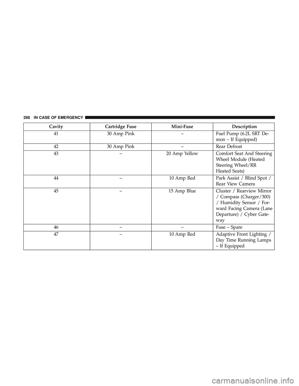
CavityCartridge Fuse Mini-FuseDescription
41 30 Amp Pink –Fuel Pump (6.2L SRT De-
mon – If Equipped)
42 30 Amp Pink –Rear Defrost
43 –20 Amp Yellow Comfort Seat And Steering
Wheel Module (Heated
Steering Wheel/RR
Heated Seats)
44 –10 Amp Red Park Assist / Blind Spot /
Rear View Camera
45 –15 Amp Blue Cluster / Rearview Mirror
/ Compass (Charger/300)
/ Humidity Sensor / For-
ward Facing Camera (Lane
Departure) / Cyber Gate-
way
46 ––Fuse – Spare
47 –10 Amp Red Adaptive Front Lighting /
Day Time Running Lamps
– If Equipped
298 IN CASE OF EMERGENCY