inflation pressure DODGE CHARGER SRT 2018 Owners Manual
[x] Cancel search | Manufacturer: DODGE, Model Year: 2018, Model line: CHARGER SRT, Model: DODGE CHARGER SRT 2018Pages: 490, PDF Size: 5.08 MB
Page 128 of 490
Should one or more tires be in the condition mentioned
above, the display will show the indications corresponding
to each tire.
CAUTION!
Do not continue driving with one or more flat tires as
handling may be compromised. Stop the vehicle,
avoiding sharp braking and steering. If a tire puncture
occurs, repair immediately using the dedicated tire
repair kit and contact your authorized dealer as soon as
possible.
Each tire, including the spare (if provided), should be
checked monthly when cold and inflated to the inflation
pressure recommended by the vehicle manufacturer on the
vehicle placard or tire inflation pressure label. (If your
vehicle has tires of a different size than the size indicated
on the vehicle placard or tire inflation pressure label, you
should determine the proper tire inflation pressure for
those tires.)
As an added safety feature, your vehicle has been
equipped with a Tire Pressure Monitoring System (TPMS)
that illuminates a low tire pressure telltale when one or more of your tires is significantly under-inflated. Accord-
ingly, when the low tire pressure telltale illuminates, you
should stop and check your tires as soon as possible, and
inflate them to the proper pressure. Driving on a signifi-
cantly under-inflated tire causes the tire to overheat and
can lead to tire failure. Under-inflation also reduces fuel
efficiency and tire tread life, and may affect the vehicle’s
handling and stopping ability.
Please note that the TPMS is not a substitute for proper tire
maintenance, and it is the driver ’s responsibility to main-
tain correct tire pressure, even if under-inflation has not
reached the level to trigger illumination of the TPMS low
tire pressure telltale.
Your vehicle has also been equipped with a TPMS malfunc-
tion indicator to indicate when the system is not operating
properly. The TPMS malfunction indicator is combined
with the low tire pressure telltale. When the system detects
a malfunction, the telltale will flash for approximately one
minute and then remain continuously illuminated. This
sequence will continue upon subsequent vehicle start-ups
as long as the malfunction exists. When the malfunction
indicator is illuminated, the system may not be able to
detect or signal low tire pressure as intended. TPMS
malfunctions may occur for a variety of reasons, including
126 GETTING TO KNOW YOUR INSTRUMENT PANEL
Page 158 of 490
Service FCW Warning
If the system turns off, and the instrument cluster display
reads:
•ACC/FCW Unavailable Service Required
• Cruise/FCW Unavailable Service Required
This indicates there is an internal system fault. Although
the vehicle is still drivable under normal conditions, have
the system checked by an authorized dealer.
General Information
The following regulatory statement applies to all Radio
Frequency (RF) devices equipped in this vehicle:
This device complies with Part 15 of the FCC Rules and
with Industry Canada license-exempt RSS standard(s).
Operation is subject to the following two conditions:
1. This device may not cause harmful interference.
2. This device must accept any interference received, in- cluding interference that may cause undesired opera-
tion.
NOTE: Changes or modifications not expressly approved
by the party responsible for compliance could void the
user ’s authority to operate the equipment.
Tire Pressure Monitoring System (TPMS)
The Tire Pressure Monitor System (TPMS) will warn the
driver of a low tire pressure based on the vehicle recom-
mended cold placard pressure.
The tire pressure will vary with temperature by about 1 psi
(7 kPa) for every 12°F (6.5°C). This means that when the
outside temperature decreases, the tire pressure will de-
crease. Tire pressure should always be set based on cold
inflation tire pressure. This is defined as the tire pressure
after the vehicle has not been driven for at least three
hours, or driven less than 1 mile (1.6 km) after a three hour
period. The cold tire inflation pressure must not exceed the
maximum inflation pressure molded into the tire sidewall.
Refer to “Tires” in “Servicing And Maintenance” for infor-
mation on how to properly inflate the vehicle’s tires. The
tire pressure will also increase as the vehicle is driven - this
is normal and there should be no adjustment for this
increased pressure.
The TPMS will warn the driver of a low tire pressure if the
tire pressure falls below the low-pressure warning limit for
any reason, including low temperature effects and natural
pressure loss through the tire.
The TPMS will continue to warn the driver of low tire
pressure as long as the condition exists, and will not turn
156 SAFETY
Page 160 of 490
NOTE:
•The TPMS is not intended to replace normal tire care and
maintenance or to provide warning of a tire failure or
condition.
• The TPMS should not be used as a tire pressure gauge
while adjusting your tire pressure.
• Driving on a significantly under-inflated tire causes the
tire to overheat and can lead to tire failure. Under-
inflation also reduces fuel efficiency and tire tread life,
and may affect the vehicle’s handling and stopping
ability.
• The TPMS is not a substitute for proper tire mainte-
nance, and it is the driver ’s responsibility to maintain
correct tire pressure using an accurate tire pressure
gauge, even if under-inflation has not reached the level
to trigger illumination of the TPM Telltale Light.
• Seasonal temperature changes will affect tire pressure,
and the TPMS will monitor the actual tire pressure in the
tire.Premium System
The Tire Pressure Monitor System (TPMS) uses wireless
technology with wheel rim mounted electronic sensors to
monitor tire pressure levels. Sensors, mounted to each
wheel as part of the valve stem, transmit tire pressure
readings to the receiver module.
NOTE: It is particularly important for you to check the tire
pressure in all of the tires on your vehicle monthly and to
maintain the proper pressure.
The TPMS consists of the following components:
• Receiver module
• Four tire pressure monitoring sensors
• Various tire pressure monitoring system messages,
which display in the instrument cluster
• Tire pressure monitoring telltale light
158 SAFETY
Page 161 of 490
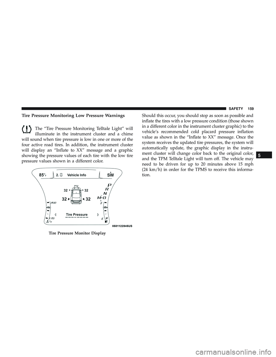
Tire Pressure Monitoring Low Pressure Warnings
The “Tire Pressure Monitoring Telltale Light” will
illuminate in the instrument cluster and a chime
will sound when tire pressure is low in one or more of the
four active road tires. In addition, the instrument cluster
will display an “Inflate to XX” message and a graphic
showing the pressure values of each tire with the low tire
pressure values shown in a different color. Should this occur, you should stop as soon as possible and
inflate the tires with a low pressure condition (those shown
in a different color in the instrument cluster graphic) to the
vehicle’s recommended cold placard pressure inflation
value as shown in the “Inflate to XX” message. Once the
system receives the updated tire pressures, the system will
automatically update, the graphic display in the instru-
ment cluster will change color back to the original color,
and the TPM Telltale Light will turn off. The vehicle may
need to be driven for up to 20 minutes above 15 mph
(24 km/h) in order for the TPMS to receive this informa-
tion.
Tire Pressure Monitor Display
5
SAFETY 159
Page 208 of 490
WARNING!(Continued)
vehicle properly parked with the engine off, fully
depress the accelerator, the brake, and the clutch
pedal (if present) to check for interference. If your
floor mat interferes with the operation of any pedal,
or is not secure to the floor, remove the floor mat
from the vehicle and place the floor mat in your
trunk.
• ONLY use the passenger ’s side floor mat on the
passenger ’s side floor area.
• ALWAYS make sure objects cannot fall or slide into
the driver ’s side floor area when the vehicle is
moving. Objects can become trapped under accelera-
tor, brake, or clutch pedals and could cause a loss of
vehicle control.
• NEVER place any objects under the floor mat (e.g.,
towels, keys, etc.). These objects could change the
position of the floor mat and may cause interference
with the accelerator, brake, or clutch pedals.
• If the vehicle carpet has been removed and re-
installed, always properly attach carpet to the floor
and check the floor mat fasteners are secure to the
vehicle carpet. Fully depress each pedal to check for
(Continued)
WARNING! (Continued)
interference with the accelerator, brake, or clutch
pedals then re-install the floor mats.
• It is recommended to only use mild soap and water
to clean your floor mats. After cleaning, always check
your floor mat has been properly installed and is
secured to your vehicle using the floor mat fasteners
by lightly pulling mat.
Periodic Safety Checks You Should Make Outside
The Vehicle
Tires
Examine tires for excessive tread wear and uneven wear
patterns. Check for stones, nails, glass, or other objects
lodged in the tread or sidewall. Inspect the tread for cuts
and cracks. Inspect sidewalls for cuts, cracks, and bulges.
Check the wheel nuts for tightness. Check the tires (includ-
ing spare) for proper cold inflation pressure.
Lights
Have someone observe the operation of brake lights and
exterior lights while you work the controls. Check turn
signal and high beam indicator lights on the instrument
panel.
206 SAFETY
Page 308 of 490
Select Knob (5) is in the Sealant Mode position and not
Air Mode. Push the Power Button (4) to turn On the Tire
Service Kit.
2. Connect the Power Plug (8) to a different 12 Volt power outlet in your vehicle or another vehicle, if available.
Make sure the engine is running before turning ON the
Tire Service Kit.
3. The Sealant Bottle (1) may be empty due to previous use. Call for assistance.
NOTE: If the Mode Select Knob (5) is on Air Mode and the
pump is operating, air will dispense from the Air Pump
Hose (7) only, not the Sealant Hose (6).
If the sealant (white fluid) does flow through the Sealant
Hose (6):
1. Continue to operate the pump until sealant is no longer flowing through the hose (typically takes 30 - 70 sec-
onds). As the sealant flows through the Sealant Hose (6),
the Pressure Gauge (3) can read as high as 70 psi (4.8
Bar). The Pressure Gauge (3) will decrease quickly from
approximately 70 psi (4.8 Bar) to the actual tire pressure
when the Sealant Bottle (1) is empty. 2. The pump will start to inject air into the tire immedi-
ately after the Sealant Bottle (1) is empty. Continue to
operate the pump and inflate the tire to the pressure
indicated on the tire pressure label on the driver-side
latch pillar (recommended pressure). Check the tire
pressure by looking at the Pressure Gauge (3).
If the tire does not inflate to at least 26 psi (1.8 Bar)
pressure within 15 minutes:
• The tire is too badly damaged. Do not attempt to drive
the vehicle further. Call for assistance.
NOTE: If the tire becomes overinflated, push the Deflation
Button (2) to reduce the tire pressure to the recommended
inflation pressure before continuing.
If the tire inflates to the recommended pressure or is at
least 26 psi (1.8 Bar) pressure within 15 minutes:
1. Push the Power Button (4) to turn off the Tire Service Kit.
2. Remove the Speed Limit sticker from the top of the Sealant Bottle (1) and place the sticker on the instrument
panel.
306 IN CASE OF EMERGENCY
Page 310 of 490
If tire pressure is less than 19 psi (1.3 Bar):
The tire is too badly damaged. Do not attempt to drive the
vehicle further. Call for assistance.
If the tire pressure is 19 psi (1.3 Bar) or higher:
1. Push the Power Button (4) to turn on Tire Service Kitand inflate the tire to the pressure indicated on the tire
and loading information label on the driver-side door
opening.
NOTE: If the tire becomes over-inflated, push the Deflation
Button to reduce the tire pressure to the recommended
inflation pressure before continuing.
2. Disconnect the Tire Service Kit from the valve stem, reinstall the cap on the valve stem and unplug from 12
Volt outlet.
3. Place the Tire Service Kit in its proper storage area in the vehicle.
4. Have the tire inspected and repaired or replaced at the earliest opportunity at an authorized dealer or tire
service center.
5. Remove the Speed Limit sticker from the instrument panel after the tire has been repaired. 6. Replace the Sealant Bottle (1) and Sealant Hose (6)
assembly at an authorized dealer as soon as possible.
Refer to “(F) Sealant Bottle And Hose Replacement”.
NOTE: When having the tire serviced, advise the autho-
rized dealer or service center that the tire has been sealed
using the Tire Service Kit.
(F) Sealant Bottle And Hose Replacement:
1. Uncoil the Sealant Hose (6) (clear in color).
2. Locate the round Sealant Bottle release button in the recessed area under the sealant bottle.
3. Push the Sealant Bottle release button. The Sealant Bottle (1) will pop up. Remove the bottle and dispose of it
accordingly.
4. Clean any remaining sealant from the Tire Service Kit housing.
5. Position the new Sealant Bottle (1) in the housing so that the Sealant Hose (6) aligns with the hose slot in the front
of the housing. Push the bottle into the housing. An
audible click will be heard indicating the bottle is locked
into place.
308 IN CASE OF EMERGENCY
Page 351 of 490
EXAMPLE:
Service Description:
95 = Load Index
–A numerical code associated with the maximum load a tire can carry
H = Speed Symbol
–A symbol indicating the range of speeds at which a tire can carry a load corresponding to its load index under cer-
tain operating conditions
–The maximum speed corresponding to the speed symbol should only be achieved under specified operating condi-
tions (i.e., tire pressure, vehicle loading, road conditions, and posted speed limits)
Load Identification:
Absence of the following load identification symbols on the sidewall of the tire indicates a Standard Load (SL) tire:
• XL = Extra load (or reinforced) tire, or
• LL = Light load tire or
• C, D, E, F, G = Load range associated with the maximum load a tire can carry at a specified pressure
Maximum Load – Maximum load indicates the maximum load this tire is designed to carry
Maximum Pressure – Maximum pressure indicates the maximum permissible cold tire inflation pressure for this tire
8
SERVICING AND MAINTENANCE 349
Page 353 of 490
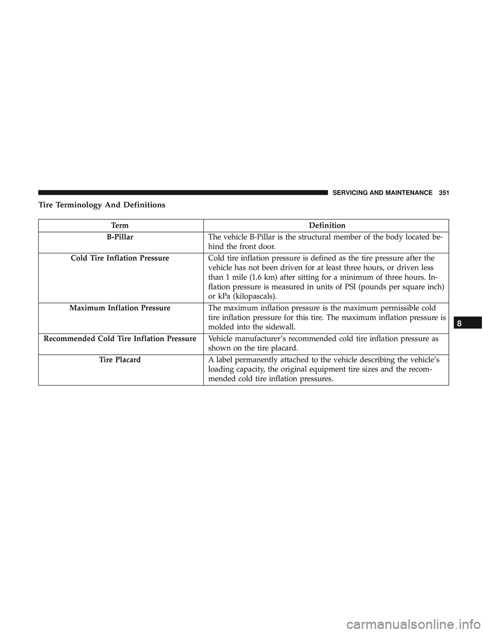
Tire Terminology And Definitions
TermDefinition
B-Pillar The vehicle B-Pillar is the structural member of the body located be-
hind the front door.
Cold Tire Inflation Pressure Cold tire inflation pressure is defined as the tire pressure after the
vehicle has not been driven for at least three hours, or driven less
than 1 mile (1.6 km) after sitting for a minimum of three hours. In-
flation pressure is measured in units of PSI (pounds per square inch)
or kPa (kilopascals).
Maximum Inflation Pressure The maximum inflation pressure is the maximum permissible cold
tire inflation pressure for this tire. The maximum inflation pressure is
molded into the sidewall.
Recommended Cold Tire Inflation Pressure Vehicle manufacturer’s recommended cold tire inflation pressure as
shown on the tire placard.
Tire Placard A label permanently attached to the vehicle describing the vehicle’s
loading capacity, the original equipment tire sizes and the recom-
mended cold tire inflation pressures.
8
SERVICING AND MAINTENANCE 351
Page 354 of 490
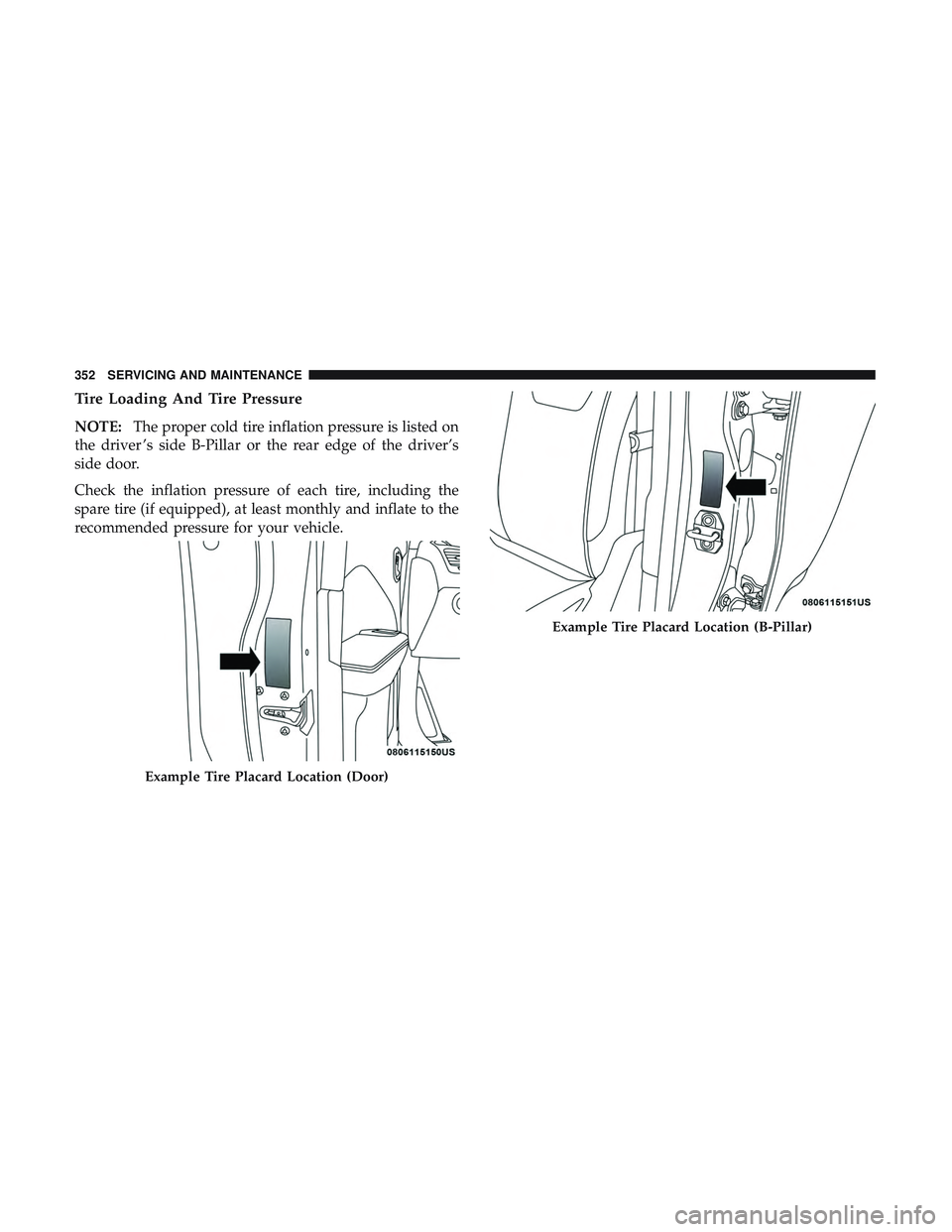
Tire Loading And Tire Pressure
NOTE:The proper cold tire inflation pressure is listed on
the driver ’s side B-Pillar or the rear edge of the driver’s
side door.
Check the inflation pressure of each tire, including the
spare tire (if equipped), at least monthly and inflate to the
recommended pressure for your vehicle.
Example Tire Placard Location (Door)
Example Tire Placard Location (B-Pillar)
352 SERVICING AND MAINTENANCE