oil pressure DODGE CHARGER SRT 2018 Owners Manual
[x] Cancel search | Manufacturer: DODGE, Model Year: 2018, Model line: CHARGER SRT, Model: DODGE CHARGER SRT 2018Pages: 490, PDF Size: 5.08 MB
Page 110 of 490
3. Speedometer•Indicates vehicle speed.
4. Fuel Gauge •The pointer shows the level of fuel in the fuel tank
when the Keyless Push Button Ignition is in the
ON/RUN position.
•
The fuel pump symbol points to the side of the
vehicle where the fuel door is located.
5. Temperature Gauge
•The temperature gauge shows engine coolant tem-
perature. Any reading within the normal range indi-
cates that the engine cooling system is operating
satisfactorily.
• The gauge pointer will likely indicate a higher tem-
perature when driving in hot weather, up mountain
grades, or when towing a trailer. It should not be
allowed to exceed the upper limits of the normal
operating range.
WARNING!
A hot engine cooling system is dangerous. You or
others could be badly burned by steam or boiling
(Continued)
WARNING! (Continued)
coolant. You may want to call an authorized dealer for
service if your vehicle overheats. If you decide to look
under the hood yourself, see “Servicing And Mainte-
nance.” Follow the warnings under the Cooling System
Pressure Cap paragraph.
CAUTION!
Driving with a hot engine cooling system could dam-
age your vehicle. If the temperature gauge reads “H,”
pull over and stop the vehicle. Idle the vehicle with the
air conditioner turned off until the pointer drops back
into the normal range. If the pointer remains on the
“H,” turn the engine off immediately and call an
authorized dealer for service.
NOTE: The hard telltales will illuminate for a bulb check
when the ignition is first cycled.
108 GETTING TO KNOW YOUR INSTRUMENT PANEL
Page 114 of 490
Secondary Method Of Resetting Engine Oil Life
1. Without pressing the brake pedal, push the ENGINESTART/STOP button and place the ignition to the
ON/RUN position (do not start the engine).
2. Fully press the accelerator pedal, slowly, three times within ten seconds.
3. Without pushing the brake pedal, push the ENGINE START/STOP button once to return the ignition to the
OFF/LOCK position.
NOTE: If the indicator message illuminates when you start
the vehicle, the oil change indicator system did not reset. If
necessary, repeat this procedure.
Performance Shift Indicator (PSI) — If Equipped
The Performance Shift Indicator (PSI) is enabled on ve-
hicles with manual transmission, or when a vehicle with
automatic transmission is in manual shift mode. The PSI
provides the driver with a visual indication within the
instrument cluster display when the driver configured gear
shift point has been reached and the driver is still acceler-
ating. This indication notifies the driver to change gear
corresponding to the configured RPMs in the head unit.
Instrument Cluster Display Selectable Menu Items
Push and release the upordown arrow button until the
desired Selectable Menu item is displayed in the instru-
ment cluster display.
Follow the Menu or submenu prompts as desired.
Speedometer
Push and release the upordown arrow button until the
speedometer menu is displayed in the instrument cluster
display. Push and release the OKbutton to toggle units
(km/h or MPH) of the speedometer.
Vehicle Info
Push and release the upordown arrow button until the
“Vehicle Info” menu is displayed in the instrument cluster
display. Push and release the rightorleft arrow button to
scroll through the submenus items of “Vehicle Info.” Fol-
low the directional prompts to access or reset any of the
following “Vehicle Info” submenu items:
• Tire Pressure Monitor
• Coolant Temp
• Trans Temp
• Oil Temp
112 GETTING TO KNOW YOUR INSTRUMENT PANEL
Page 115 of 490
•Oil Pressure
• Oil Life
• Battery Voltage
• Storage Mode
• Through this option, the vehicle can be placed into
Storage Mode.
• Intake Air Temp
• Engine Torque
• Engine Power
• Air-Fuel Ratio — If Equipped
• Boost Pressure — If Equipped
• Intercooler (I/C) Temp — If Equipped
Performance Features
WARNING!
Measurement of vehicle statistics with the Perfor-
mance Features is intended for off-highway or track
use only and should not be done on any public
roadways. It is recommended that these features be
(Continued)
WARNING! (Continued)
used in a controlled environment and within the limits
of the law. The capabilities of the vehicle as measured
by the performance pages must never be exploited in a
reckless or dangerous manner, which can jeopardize
the user ’s safety or the safety of others. Only a safe,
attentive, and skillful driver can prevent accidents.
Push and release the upordown arrow button until the
Performance menu is displayed in the instrument cluster
display. Push the rightorleft arrow button to enter the
submenus.
The Performance Features include the following:
• 0-60 MPH (0-100 km/h) Timer
– Best
– Last
– Current
– Reaction Timer
• 0-100 MPH (0-161 km/h) Timer
– Best
– Last
– Current
– Reaction Timer
4
GETTING TO KNOW YOUR INSTRUMENT PANEL 113
Page 124 of 490
WARNING!
Continued operation with reduced assist could pose a
safety risk to yourself and others. Service should be
obtained as soon as possible.
—Electronic Throttle Control (ETC) Warning Light
This warning light will illuminate to indicate a problem
with the Electronic Throttle Control (ETC) system. If a
problem is detected while the vehicle is running, the light
will either stay on or flash depending on the nature of the
problem. Cycle the ignition when the vehicle is safely and
completely stopped and the transmission is placed in the
PARK position. The light should turn off. If the light
remains on with the vehicle running, your vehicle will
usually be drivable; however, see an authorized dealer for
service as soon as possible.
NOTE:This light may turn on if the accelerator and brake
pedals are pressed at the same time.
If the light continues to flash when the vehicle is running,
immediate service is required and you may experience
reduced performance, an elevated/rough idle, or engine
stall and your vehicle may require towing. The light will
come on when the ignition is placed in the ON/RUN or ACC/ON/RUN position and remain on briefly as a bulb
check. If the light does not come on during starting, have
the system checked by an authorized dealer.
— Engine Coolant Temperature Warning Light
This warning light warns of an overheated engine condi-
tion. If the engine coolant temperature is too high, this
indicator will illuminate and a single chime will sound. If
the temperature reaches the upper limit, a continuous
chime will sound for four minutes or until the engine is
able to cool: whichever comes first.
If the light turns on while driving, safely pull over and stop
the vehicle. If the A/C system is on, turn it off. Also, shift
the transmission into NEUTRAL and idle the vehicle. If the
temperature reading does not return to normal, turn the
engine off immediately and call for service.
Refer to “If Your Engine Overheats” in “In Case Of
Emergency” for further information.
— Oil Pressure Warning Light
This warning light will illuminate to indicate low engine
oil pressure. If the light turns on while driving, stop the
vehicle, shut off the engine as soon as possible, and contact
an authorized dealer. A chime will sound when this light
turns on.
122 GETTING TO KNOW YOUR INSTRUMENT PANEL
Page 309 of 490
3. Immediately disconnect the Sealant Hose (6) from thevalve stem, reinstall the cap on the fitting at the end of
the hose, and place the Tire Service Kit in the vehicle
storage location. Quickly proceed to (D) “Drive Ve-
hicle.”
CAUTION!
•The metal end fitting from Power Plug (8) may get
hot after use, so it should be handled carefully.
• Failure to reinstall the cap on the fitting at the end of
the Sealant Hose (6) can result in sealant contacting
your skin, clothing, and the vehicle’s interior. It can
also result in sealant contacting internal Tire Service
Kit components which may cause permanent damage
to the kit.
(D) Drive Vehicle:
Immediately after injecting sealant and inflating the tire,
drive the vehicle 5 miles (8 km) or ten minutes to ensure
distribution of the Tire Service Kit Sealant within the tire.
Do not exceed 50 mph (80 km/h).
WARNING!
Tire Service Kit is not a permanent flat tire repair. Have
the tire inspected and repaired or replaced after using
Tire Service Kit. Do not exceed 50 mph (80 km/h) until
the tire is repaired or replaced. Failure to follow this
warning can result in injuries that are serious or fatal
to you, your passengers, and others around you.
(E) After Driving:
Pull over to a safe location. Refer to “Whenever You Stop
To Use Tire Service Kit” before continuing.
1. Push in the Mode Select Knob (5) and turn to the Air
Mode position.
2. Uncoil the power plug and insert the plug into the vehicle’s 12 Volt power outlet.
3. Uncoil the Air Pump Hose (7) (black in color) and screw the fitting at the end of hose (7) onto the valve stem.
4. Check the pressure in the tire by reading the Pressure Gauge (3).7
IN CASE OF EMERGENCY 307
Page 310 of 490
If tire pressure is less than 19 psi (1.3 Bar):
The tire is too badly damaged. Do not attempt to drive the
vehicle further. Call for assistance.
If the tire pressure is 19 psi (1.3 Bar) or higher:
1. Push the Power Button (4) to turn on Tire Service Kitand inflate the tire to the pressure indicated on the tire
and loading information label on the driver-side door
opening.
NOTE: If the tire becomes over-inflated, push the Deflation
Button to reduce the tire pressure to the recommended
inflation pressure before continuing.
2. Disconnect the Tire Service Kit from the valve stem, reinstall the cap on the valve stem and unplug from 12
Volt outlet.
3. Place the Tire Service Kit in its proper storage area in the vehicle.
4. Have the tire inspected and repaired or replaced at the earliest opportunity at an authorized dealer or tire
service center.
5. Remove the Speed Limit sticker from the instrument panel after the tire has been repaired. 6. Replace the Sealant Bottle (1) and Sealant Hose (6)
assembly at an authorized dealer as soon as possible.
Refer to “(F) Sealant Bottle And Hose Replacement”.
NOTE: When having the tire serviced, advise the autho-
rized dealer or service center that the tire has been sealed
using the Tire Service Kit.
(F) Sealant Bottle And Hose Replacement:
1. Uncoil the Sealant Hose (6) (clear in color).
2. Locate the round Sealant Bottle release button in the recessed area under the sealant bottle.
3. Push the Sealant Bottle release button. The Sealant Bottle (1) will pop up. Remove the bottle and dispose of it
accordingly.
4. Clean any remaining sealant from the Tire Service Kit housing.
5. Position the new Sealant Bottle (1) in the housing so that the Sealant Hose (6) aligns with the hose slot in the front
of the housing. Push the bottle into the housing. An
audible click will be heard indicating the bottle is locked
into place.
308 IN CASE OF EMERGENCY
Page 324 of 490
At Each Stop For Fuel
•Check the engine oil level. Refer to “Engine Compart-
ment” in this chapter for further information.
• Check the windshield washer solvent and add if re-
quired.
Once A Month
• Check tire pressure and look for unusual wear or
damage.
• Inspect the battery, and clean and tighten the terminals
as required.
• Check the fluid levels of the coolant reservoir, brake
master cylinder, and power steering (6.2L only), and add
as needed.
• Check all lights and other electrical items for correct
operation. At Each Oil Change
•
Change the engine oil filter.
• Inspect the brake hoses and lines.
CAUTION!
Failure to perform the required maintenance items
may result in damage to the vehicle.
322 SERVICING AND MAINTENANCE
Page 327 of 490
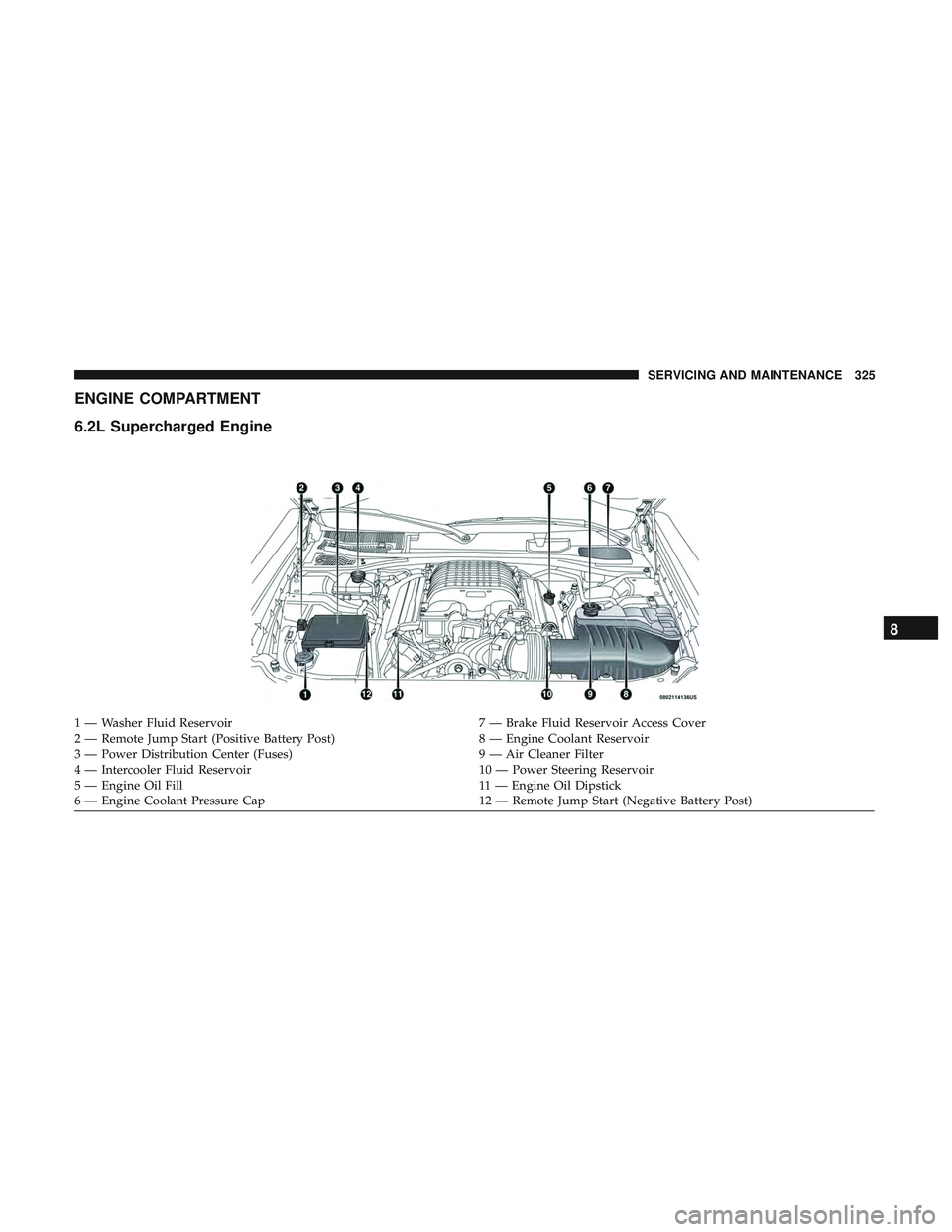
ENGINE COMPARTMENT
6.2L Supercharged Engine
1 — Washer Fluid Reservoir7 — Brake Fluid Reservoir Access Cover
2 — Remote Jump Start (Positive Battery Post) 8 — Engine Coolant Reservoir
3 — Power Distribution Center (Fuses) 9 — Air Cleaner Filter
4 — Intercooler Fluid Reservoir 10 — Power Steering Reservoir
5 — Engine Oil Fill 11 — Engine Oil Dipstick
6 — Engine Coolant Pressure Cap 12 — Remote Jump Start (Negative Battery Post)
8
SERVICING AND MAINTENANCE 325
Page 328 of 490
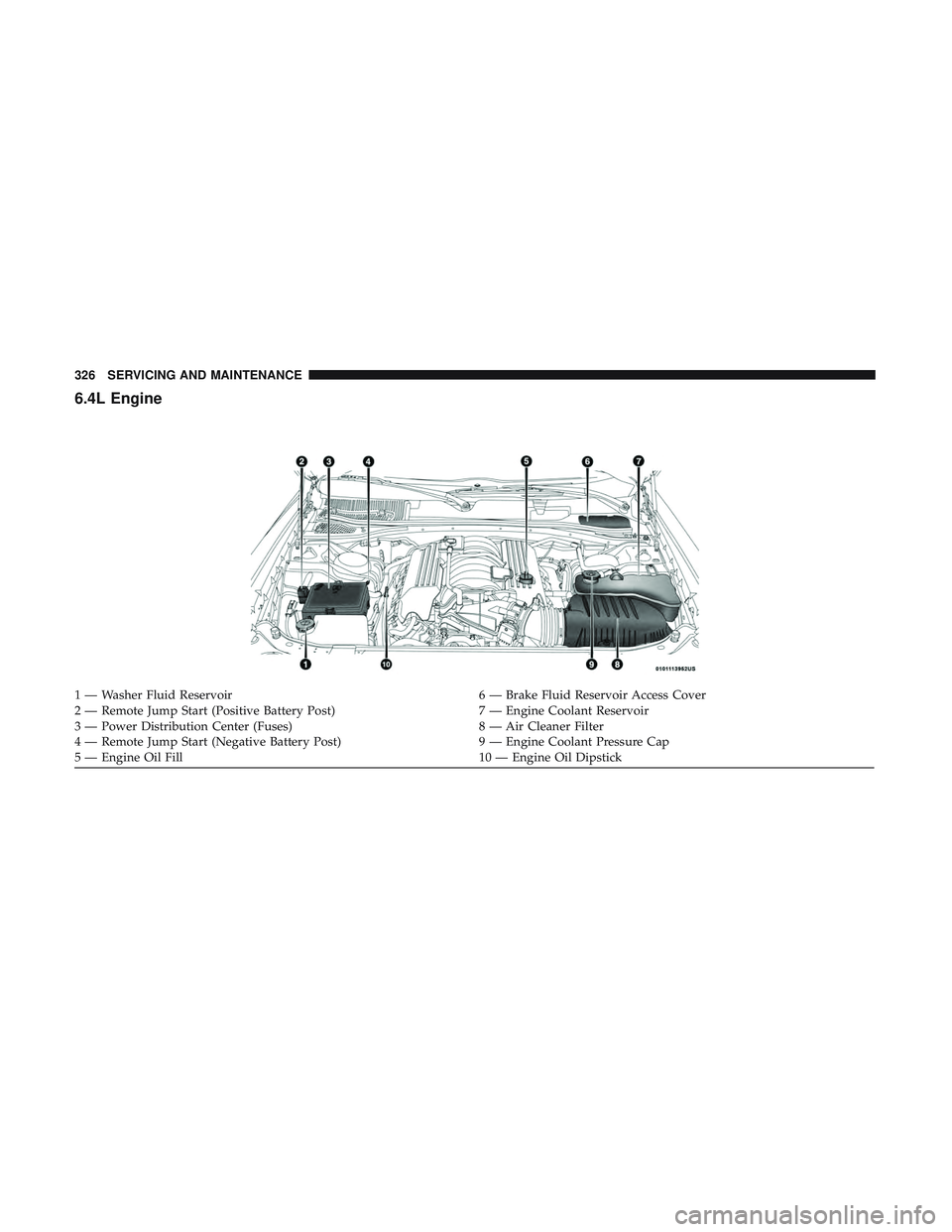
6.4L Engine
1 — Washer Fluid Reservoir6 — Brake Fluid Reservoir Access Cover
2 — Remote Jump Start (Positive Battery Post) 7 — Engine Coolant Reservoir
3 — Power Distribution Center (Fuses) 8 — Air Cleaner Filter
4 — Remote Jump Start (Negative Battery Post) 9 — Engine Coolant Pressure Cap
5 — Engine Oil Fill 10 — Engine Oil Dipstick
326 SERVICING AND MAINTENANCE
Page 329 of 490
Checking Oil Level
To assure proper engine lubrication, the engine oil must be
maintained at the correct level. Check the oil level at
regular intervals, such as once a month. The best time to
check the engine oil level is about five minutes after a fully
warmed engine is shut off.
Checking the oil while the vehicle is on level ground will
improve the accuracy of the oil level readings. Maintain the
oil level in the “SAFE” range. Adding 1.0 quart (1 liter) of
oil when the reading is at the bottom of the “SAFE” range
will result in an oil level at the top of the “SAFE” range on
these engines.
CAUTION!
Overfilling or underfilling the crankcase will cause
aeration or loss of oil pressure. This could damage your
engine.
Adding Washer Fluid
The windshield washer fluid reservoir is located in the
front of the engine compartment. Be sure to check the fluid
level at regular intervals. Fill the reservoir with windshield
washer solvent (not radiator antifreeze) and operate the
system for a few seconds to flush out the residual water.When refilling the washer fluid reservoir, apply some
washer fluid to a cloth or towel and wipe the wiper blades
clean. This will help blade performance.
To prevent freeze-up of your windshield washer system in
cold weather, select a solution or mixture that meets or
exceeds the temperature range of your climate. This rating
information can be found on most washer fluid containers.
The fluid reservoir will hold nearly 1 gallon (4 liters) of
washer fluid when the message “Low Washer Fluid”
appears in the instrument cluster.
WARNING!
Commercially available windshield washer solvents
are flammable. They could ignite and burn you. Care
must be exercised when filling or working around the
washer solution.
Maintenance-Free Battery
Your vehicle is equipped with a maintenance-free battery.
You will never have to add water, nor is periodic mainte-
nance required.
8
SERVICING AND MAINTENANCE 327