light DODGE DAKOTA 2008 3.G Owners Manual
[x] Cancel search | Manufacturer: DODGE, Model Year: 2008, Model line: DAKOTA, Model: DODGE DAKOTA 2008 3.GPages: 426, PDF Size: 6.39 MB
Page 321 of 426
WARNING!
Raising the vehicle higher than necessary can make
the vehicle unstable and cause an accident. It could
slip off the jack and hurt someone near it. Raise the
vehicle only enough to remove the tire.
5. Remove the wheel nuts and pull the wheel off. Install
the spare wheel and wheel nuts with the cone shaped end
of the nuts toward the wheel. Lightly tighten the nuts. To
avoid risk of forcing the vehicle off the jack, do not fully
tighten the nuts until the vehicle has been lowered.
6. Using the wheel wrench, finish tightening the nuts in
a crisscross pattern. Correct nut tightness is 130-160 ft.
lbs. (177-217 N´m). If in doubt about the correct tightness,
have them checked with a torque wrench by your dealer
or at a service station.
WARNING!
A loose tire or jack thrown forward in a collision or
hard stop could injure someone in the vehicle. Al-
ways stow the jack, tools and the extra tire and wheel
in the places provided.
7. Lower the jack to its fully closed position. Stow the
replaced tire, jack, and tools as previously described.
8. Adjust the tire pressure when possible.
NOTE:Do not oil wheel studs. For chrome wheels, do
not substitute with chrome plated wheel nuts.
WHAT TO DO IN EMERGENCIES 321
6
Page 323 of 426
JUMP STARTING
WARNING!
²Battery fluid is a corrosive acid solution; do not
allow battery fluid to contact eyes, skin or cloth-
ing. Don't lean over battery when attaching
clamps or allow the clamps to touch each other. If
acid splashes in eyes or on skin, flush the contami-
nated area immediately with large quantities of
water.
²A battery generates hydrogen gas which is flam-
mable and explosive. Keep flame or spark away
from the vent holes. Do not use a booster battery
or any other booster source with an output that
exceeds 12 volts.Check the Battery Test Indicator (if equipped). If a light or
bright colored dot is visible in the indicator (if equipped),
DO NOT jump-start the battery.
If the indicator (if equipped) is dark or shows a green dot,
proceed as follows:
1. Wear eye protection and remove all metal jewelry such
as watch bands or bracelets which might make an
unintended electrical contact.
2. Park the booster vehicle within cable reach but with-
out letting the vehicles touch. Set the parking brake, place
the automatic transmission in PARK and turn the ignition
OFF on both vehicles.
3. Turn OFF heater, radio and all unnecessary electrical
loads.
WHAT TO DO IN EMERGENCIES 323
6
Page 325 of 426
6. Start the engine in the vehicle which has the booster
battery, let the engine idle a few minutes, then start the
engine in the vehicle with the discharged battery.
7. When removing the jumper cables, reverse the above
sequence exactly. Be careful of the moving belts and fan.
WARNING!
Any procedure other than above could result in:
1. Personal injury caused by electrolyte squirting out
the battery vent;
2. Personal injury or property damage due to battery
explosion;
3. Damage to charging system of booster vehicle or
of immobilized vehicle.
FREEING A STUCK VEHICLE
If vehicle becomes stuck in snow, sand, or mud, it can
often be moved by a rocking motion. Move the gear
selector rhythmically between FIRST and REVERSE,
while applying slight pressure to the accelerator.
The least amount of accelerator pedal pressure to main-
tain the rocking motion without spinning the wheels or
racing the engine is most effective. Allow the engine to
idle with the transmission selector in NEUTRAL for at
least one minute after every five rocking-motion cycles.
This will minimize overheating and reduce the risk of
transmission failure during prolonged efforts to free a
stuck vehicle.
WHAT TO DO IN EMERGENCIES 325
6
Page 330 of 426

NPower Steering Ð Fluid Check............347
NFront Suspension Ball Joints..............348
NDrive Shaft Constant Velocity Joints........348
NBody Lubrication.....................348
NWindshield Wiper Blades................349
NWindshield Washers...................349
NExhaust System......................350
NCooling System.......................351
NEmission Related Components............356
NBrake System........................357
NClutch Hydraulic System................359
NManual Transmission..................359
NAutomatic Transmission................359NTransfer Case........................362
NAxles..............................362
NAppearance Care And Protection
From Corrosion......................363
mFuses (Power Distribution Center)...........367
mVehicle Storage........................373
mReplacement Light Bulbs.................373
mBulb Replacement......................374
NHeadlight (Halogen)/Front Park And
Turn Lights.........................374
NRear Side Marker, Taillamps/Stoplamp,
And Turn Signal Bulbs Ð Replacement......377
NCenter High-Mounted Stoplamp And
Cargo Lamp.........................379
330 MAINTAINING YOUR VEHICLE
Page 334 of 426
ONBOARD DIAGNOSTIC SYSTEM Ð OBD II
Your vehicle is equipped with a sophisticated onboard
diagnostic system called OBD II. This system monitors
the performance of the emissions, engine, and automatic
transmission control systems. When these systems are
operating properly, your vehicle will provide excellent
performance and fuel economy, as well as engine emis-
sions well within current government regulations.
If any of these systems require service, the OBD II system
will turn on the ªMalfunction Indicator Light.º It will
also store diagnostic codes and other information to
assist your service technician in making repairs. Al-
though your vehicle will usually be drivable and not
need towing, see your dealer for service as soon as
possible.CAUTION!
²Prolonged driving with the ªMalfunction Indica-
tor Lightº on could cause further damage to the
emission control system. It could also affect fuel
economy and driveability. The vehicle must be
serviced before any emissions tests can be per-
formed.
²If the ªMalfunction Indicator Lightº is flashing
while the engine is running, severe catalytic con-
verter damage and power loss will soon occur.
Immediate service is required.
334 MAINTAINING YOUR VEHICLE
Page 335 of 426

Loose Fuel Filler Cap Message
After fuel is added, the vehicle diagnostic system can
determine if the fuel filler cap is possibly loose, improp-
erly installed, or damaged. A loose fuel filler cap message
will be displayed in the instrument cluster. Tighten the
gas cap until a9clicking9sound is heard. This is an
indication that the gas cap is properly tightened. Press
the odometer reset button to turn the message off. If the
problem persists, the message will appear the next time
the vehicle is started. This might indicate a damaged cap.
If the problem is detected twice in a row, the system will
turn on the Malfunction Indicator Light (MIL). Resolving
the problem will turn the MIL light off.
EMISSIONS INSPECTION AND MAINTENANCE
PROGRAMS
In some localities, it may be a legal requirement to pass
an inspection of your vehicle's emissions control system.
Failure to pass could prevent vehicle registration.
For states which have an I/M (Inspection and
Maintenance) requirement, this check verifies the
following: the MIL (Malfunction Indicator Lamp)
is functioning and is not on when the engine is running,
and that the OBD (On Board Diagnostic) system is ready
for testing.
Normally, the OBD system will be ready. The OBD
system maynotbe ready if your vehicle was recently
serviced, if you recently had a dead battery, or a battery
replacement. If the OBD system is determined not ready
for the I/M test, your vehicle may fail the test.
MAINTAINING YOUR VEHICLE 335
7
Page 336 of 426

Your vehicle has a simple ignition key actuated test
which you can use prior to going to the test station. To
check if your vehicle's OBD system is ready, you must do
the following:
1. Insert your ignition key into the ignition switch.
2. Turn the ignition to the ON position, but do not crank
or start the engine. If you crank or start the engine, you
will have to start this test over.
3. As soon as you turn your key to the ON position, you
will see your MIL symbol come on as part of a normal
bulb check.
4. Approximately 15 seconds later, one of two things will
happen:
a. The MIL light will blink for approximately 5 sec-
onds and then remain on until the first engine crank or
the key is turned off. This means that your vehicle's
OBD system isnot readyand you shouldnotproceed
to the I/M station.b. The MIL light will remain fully illuminated until the
first engine crank or the key is turned off. This means
that your vehicle's OBD system isreadyand you can
proceed to the I/M station.
If your OBD system isnot readyyou should see your
dealer or repair facility. If your vehicle was recently
serviced or had a battery failure or replacement, you may
need to do nothing more than drive your vehicle as you
normally would in order for your OBD system to update.
A recheck with the above test routine may then indicate
that the system is now ready.
Regardless of whether your vehicle's OBD system is
ready or not ready, if the MIL symbol is illuminated
during normal vehicle operation, you should have your
vehicle serviced before going to the I/M station. The I/M
station can fail your vehicle because the MIL symbol is on
with the engine running.
336 MAINTAINING YOUR VEHICLE
Page 357 of 426
attempt to clean the oil PCV valve!Check ventilating
hose for indication of damage or plugging with deposits.
Replace if necessary.
Brake System
Power Disc Brakes (Front)
Disc brakes do not require adjustment; however, several
hard stops during the break-in period are recommended
to seat the linings and wear off any foreign material.
Brake Master Cylinders
The fluid level in the master cylinders should be checked
whenever the vehicle is serviced, or immediately if the
brake system warning light is on. If necessary, add fluid
to bring level to the full mark on the side of the reservoir
of the brake master cylinder. Be sure to clean the top of
the master cylinder area before removing the cap. With
disc brakes, fluid level can be expected to fall as the brakepads wear. Brake fluid level should be checked when
pads are replaced. If the brake fluid level is abnormally
low, check system for leaks.
Refer to Fluids, Lubricants and Genuine Parts for correct
fluid type.
WARNING!
Use of brake fluid that may have a lower initial
boiling point, or is unidentified as to specifications,
may result in sudden brake failure during hard
prolonged braking. You could have an accident.
MAINTAINING YOUR VEHICLE 357
7
Page 361 of 426
To prevent dirt and water from entering the transmission
after checking or replenishing fluid, make certain that the
dipstick cap is properly reseated. It is normal for the
dipstick cap to spring back slightly from its fully seated
position, as long as its seal remains engaged in the
dipstick tube.
Automatic Transmission Fluid And Filter Change
Follow the proper Maintenance Schedule for your type of
driving.
Selection of Lubricant
It is important that the proper lubricant is used in the
transmission to assure optimum transmission perfor-
mance. Use only manufacturer 's recommended transmis-
sion fluid; refer to Fluids, Lubricants and Genuine Parts
for correct fluid type. It is important that the transmission
fluid be maintained at the prescribed level using the
recommended fluid.
CAUTION!
Using a transmission fluid other than the manufac-
turers recommended fluid may cause deterioration in
transmission shift quality and/or torque converter
shudder. Using a transmission fluid other than the
manufacturers recommended fluid will result in
more frequent fluid and filter changes.
Special Additives
Automatic Transmission Fluid (ATF) is an engineered
product and its performance may be impaired by supple-
mental additives. Therefore, do not add any fluid addi-
tives to the transmission. The only exception to this
policy is the use of special dyes to aid in detecting fluid
leaks. In addition, avoid using transmission sealers as
they may adversely affect seals.
MAINTAINING YOUR VEHICLE 361
7
Page 370 of 426
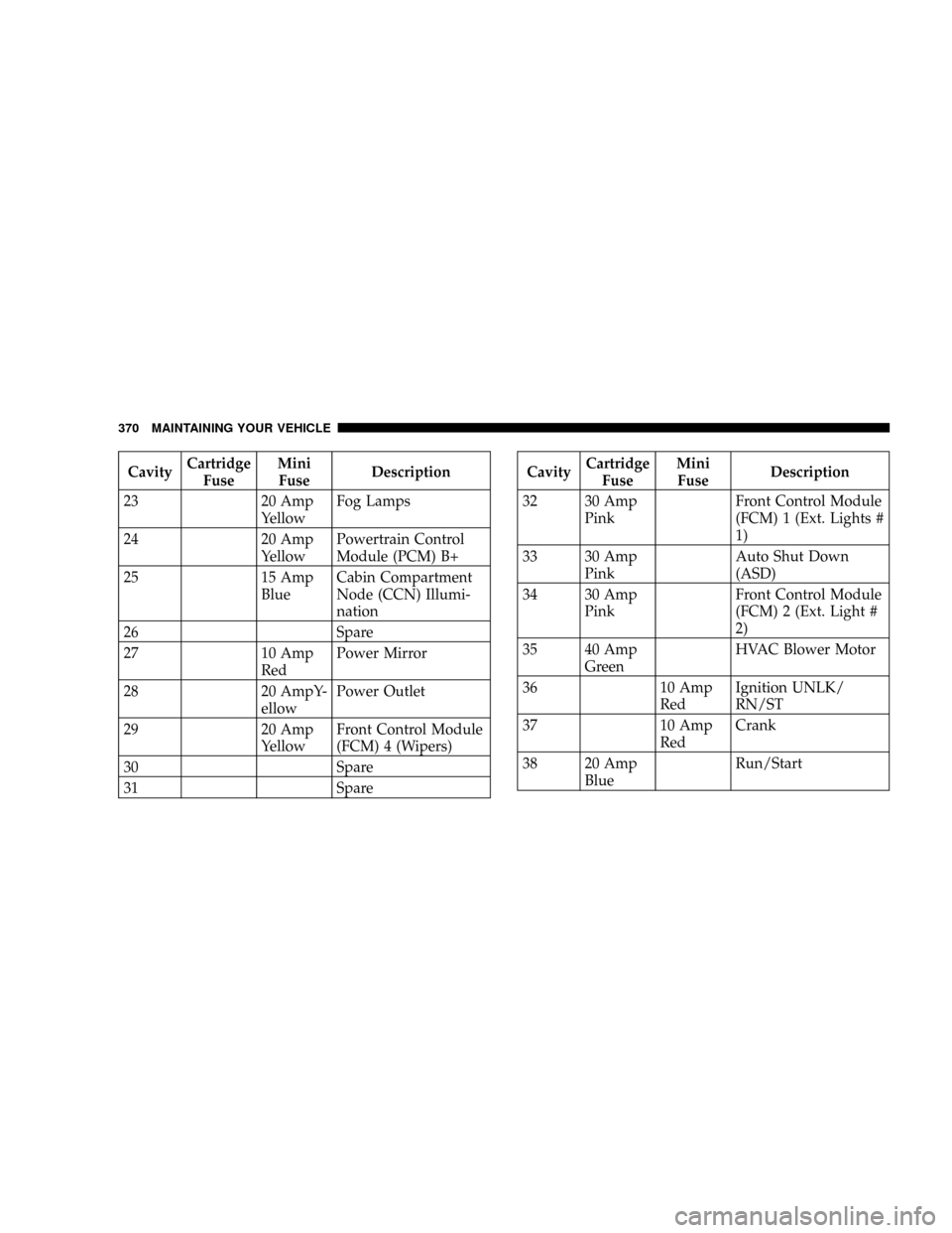
CavityCartridge
FuseMini
FuseDescription
23 20 Amp
YellowFog Lamps
24 20 Amp
YellowPowertrain Control
Module (PCM) B+
25 15 Amp
BlueCabin Compartment
Node (CCN) Illumi-
nation
26 Spare
27 10 Amp
RedPower Mirror
28 20 AmpY-
ellowPower Outlet
29 20 Amp
YellowFront Control Module
(FCM) 4 (Wipers)
30 Spare
31 SpareCavityCartridge
FuseMini
FuseDescription
32 30 Amp
PinkFront Control Module
(FCM) 1 (Ext. Lights #
1)
33 30 Amp
PinkAuto Shut Down
(ASD)
34 30 Amp
PinkFront Control Module
(FCM) 2 (Ext. Light #
2)
35 40 Amp
GreenHVAC Blower Motor
36 10 Amp
RedIgnition UNLK/
RN/ST
37 10 Amp
RedCrank
38 20 Amp
BlueRun/Start
370 MAINTAINING YOUR VEHICLE