towing DODGE DAKOTA 2009 3.G User Guide
[x] Cancel search | Manufacturer: DODGE, Model Year: 2009, Model line: DAKOTA, Model: DODGE DAKOTA 2009 3.GPages: 449, PDF Size: 10.96 MB
Page 253 of 449
cause damage to the transmission. The torque converter
will refill within five seconds of shifting from PARK into
any other gear position.
FOUR-WHEEL DRIVE OPERATION
NV233/243 GII Transfer Case Operating
Information/Precautions
The NV233/243 is an electric-shift transfer case and is
operated by the 4WD Control Switch (Transfer Case
Switch), which is located on the instrument panel.
The NV233/243 transfer case provides four mode posi-
tions: 2 (rear) wheel drive high range, 4 wheel drive high
range, 4 wheel drive low range, and NEUTRAL.
The NV233/243 transfer case is designed to be driven in
the 2-wheel drive position (2WD) for normal street and
highway conditions (dry hard-surfaced roads).
When additional traction is required, the transfer case
4WD LOCK and 4WD LOW positions can be used to lockthe front and rear driveshafts together and force the front
and rear wheels to rotate at the same speed. This is
accomplished by rotating the 4WD Control Switch to the
desired position - Refer to ªShifting Procedureº in this
section. The 4WD LOCK and 4WD LOW positions are
designed for loose or slippery road surfaces only. Driving
in the 4WD LOCK and 4WD LOW positions on dry
hard-surfaced roads may cause increased tire wear and
damage to the driveline components.
The transfer case NEUTRAL position is selected by
depressing the recessed button located on the lower
left-hand corner of the 4WD Control Switch.
NOTE:The transfer case NEUTRAL position is to be
used for recreational towing only. Refer to ªRecreational
Towingº in Section 5 for specific procedures on shifting
into and out of NEUTRAL.
STARTING AND OPERATING 251
5
Page 256 of 449
For additional information on the appropriate use of each
transfer case mode position, refer to the following infor-
mation:
2WD
The 2±Wheel Drive (Rear-Wheel Drive) High Range is
used for normal street and highway driving, on dry,
hard-surfaced roads.
4WD LOCK
The 4-Wheel Drive Lock (4WD LOCK) Range locks the
front and rear driveshafts together, forcing the front and
rear wheels to rotate at the same speed. This range
provides additional traction for loose or slippery road
surfaces only.4WD LOW
The 4-Wheel Drive Low (4WD LOW) Range provides
low speed 4-wheel drive. It locks the front and rear
driveshafts together, forcing the front and rear wheels to
rotate at the same speed. This range provides additional
traction and maximum pulling power for loose or slip-
pery road surfaces only. Do not exceed 25 mph
(40 km/h).
N
The NEUTRAL Range disengages both the front and rear
driveshafts from the powertrain. NEUTRAL is used for
flat towing behind another vehicle. Refer to ªRecreational
Towingº in Section 5.
254 STARTING AND OPERATING
Page 260 of 449
roads. This feature provides the safety, security, and
convenience of operating in all-wheel drive at all times
regardless of road conditions.
When additional traction is required, the 4WD LOCK
and 4WD LOW positions can be used to lock the front
and rear driveshafts together, through the transfer case
inter-axle differential, and force the front and rear wheels
to rotate at the same speed. This is accomplished by
rotating the 4WD Control Switch to these positions. The
4WD LOCK and 4WD LOW positions are intended for
loose, slippery road surfaces only. Driving in the 4WD
LOCK and 4WD LOW positions on dry, hard-surfaced
roads may cause increased tire wear and damage to the
driveline components.
The transfer case NEUTRAL position is selected by
depressing the recessed button located on the lower left
hand corner of the 4WD Control Switch.NOTE:The transfer case NEUTRAL position is to be
used for recreational towing only. Refer to ªRecreational
Towingº in Section 5 for specific procedures on shifting
into and out of NEUTRAL.
Transfer Case Position Indicator Lights
Transfer case position indicator lights are located on the
instrument cluster. If there are no indicator lights on or
flashing, the transfer case position is 4-wheel drive
(4WD) and indicates the current and desired transfer case
selection (4WD,4WD LOCK).
The ªSVC 4WDº warning light monitors the electric shift
4WD system. If this light remains on after engine start up
or illuminates during driving, it means that the 4WD
system is not functioning properly and that service is
required. See your authorized dealer for service.
258 STARTING AND OPERATING
Page 262 of 449
For additional information on the appropriate use of each
transfer case mode position, refer to the following infor-
mation:
4WD
The 4-Wheel Drive High Range employs the inter-axle
differential. This range allows front and rear wheels to
rotate at different speeds on all road surfaces.
4WD LOCK
The 4-Wheel Drive Lock (4WD LOCK) Range locks the
transfer case inter-axle differential, forcing the front and
rear wheels to rotate at the same speed. Additional
traction for loose, slippery road surfaces only.4WD LOW
The 4-Wheel Drive Low (4WD LOW) Range provides
low speed 4-wheel drive. It locks the front and rear
driveshafts together, forcing the front and rear wheels to
rotate at the same speed. This range provides additional
traction and maximum pulling power for loose or slip-
pery road surfaces only. Do not exceed 25 mph
(40 km/h).
N
The NEUTRAL Range disengages both the front and rear
driveshafts from the powertrain. NEUTRAL is used for
flat towing behind another vehicle. Refer to ªRecreational
Towingº in Section 5.
260 STARTING AND OPERATING
Page 279 of 449
3) tire size designed for your vehicle
4) cold tire inflation pressures for the front, rear, and
spare tires.
Loading
The vehicle maximum load on the tire must not exceed
the load carrying capacity of the tire on your vehicle. You
will not exceed the tire's load carrying capacity if you
adhere to the loading conditions, tire size, and cold tire
inflation pressures specified on the Tire and Loading
Information placard and in the ªVehicle Loadingº section
of this manual.
NOTE:Under a maximum loaded vehicle condition,
gross axle weight ratings (GAWRs) for the front and rear
axles must not be exceeded. For further information on
GAWRs, vehicle loading, and trailer towing, refer to
ªVehicle Loadingº in this section.
To determine the maximum loading conditions of your
vehicle, locate the statement ªThe combined weight ofoccupants and cargo should never exceed XXX kg or XXX
lbs.º on the Tire and Loading Information placard. The
combined weight of occupants, cargo/luggage and
trailer tongue weight (if applicable) should never exceed
the weight referenced here.
Steps for Determining Correct Load Limit
1. Locate the statement ªThe combined weight of occu-
pants and cargo should never exceed XXX kg or XXX lbsº
on your vehicle's placard.
2. Determine the combined weight of the driver and
passengers that will be riding in your vehicle.
3. Subtract the combined weight of the driver and pas-
sengers from XXX kg or XXX lbs.
4. The resulting figure equals the available amount of
cargo and luggage load capacity. For example, if ªXXXº
amount equals 1,400 lbs (635 kg) and there will be five
150 lb (68 kg) passengers in your vehicle, the amount of
STARTING AND OPERATING 277
5
Page 280 of 449
![DODGE DAKOTA 2009 3.G User Guide available cargo and luggage load capacity is 650 lbs
(295 kg) (since 5 x 150 = 750, and 1400 ± 750 = 650 lbs
[295 kg]).
5. Determine the combined weight of luggage and cargo
being loaded on the vehic DODGE DAKOTA 2009 3.G User Guide available cargo and luggage load capacity is 650 lbs
(295 kg) (since 5 x 150 = 750, and 1400 ± 750 = 650 lbs
[295 kg]).
5. Determine the combined weight of luggage and cargo
being loaded on the vehic](/img/12/5591/w960_5591-279.png)
available cargo and luggage load capacity is 650 lbs
(295 kg) (since 5 x 150 = 750, and 1400 ± 750 = 650 lbs
[295 kg]).
5. Determine the combined weight of luggage and cargo
being loaded on the vehicle. That weight may not safely
exceed the available cargo and luggage load capacity
calculated in Step 4.
6. If your vehicle will be towing a trailer, load from your
trailer will be transferred to your vehicle. Consult this
manual to determine how this reduces the available
cargo and luggage load capacity of your vehicle.NOTE:
²The following table shows examples on how to calcu-
late total load, cargo/luggage, and towing capacities
of your vehicle with varying seating configurations
and number and size of occupants. This table is for
illustration purposes only and may not be accurate for
the seating and load carry capacity of your vehicle.
²For the following example, the combined weight of
occupants and cargo should never exceed 865 lbs
(392 kg).
278 STARTING AND OPERATING
Page 312 of 449
should then be determined separately to be sure that the
load is properly distributed over front and rear axle.
Weighing the vehicle may show that the GAWR of either
the front or rear axles has been exceeded but the total
load is within the specified GVWR. If so, weight must be
shifted from front to rear or rear to front as appropriate
until the specified weight limitations are met.
Store heavier items down low and be sure that the weight
is distributed equally. Stow all loose items securely before
driving.
Improper weight distribution can have an adverse effect
on the way your vehicle steers and handles and the way
the brakes operate.WARNING!
Do not load your vehicle any heavier than the GVWR
or the maximum front and rear GAWR. If you do,
parts on your vehicle can break, or it can change the
way your vehicle handles. This could cause you to
lose control. Also, overloading can shorten the life of
your vehicle.
TRAILER TOWING
In this section you will find safety tips and information
on limits to the type of towing you can reasonably do
with your vehicle. Before towing a trailer carefully re-
view this information to tow your load as efficiently and
safely as possible.
To maintain warranty coverage, follow the requirements
and recommendations in this manual concerning ve-
hicles used for trailer towing.
310 STARTING AND OPERATING
Page 313 of 449
Common Towing Definitions
The following trailer towing related definitions will assist
you in understanding the following information:
Gross Vehicle Weight Rating (GVWR)
The GVWR is the total allowable weight of your vehicle.
This includes driver, passengers, cargo and tongue
weight. The total load must be limited so that you do not
exceed the GVWR.
Gross Trailer Weight (GTW)
The GTW is the weight of the trailer plus the weight of all
cargo, consumables and equipment (permanent or tem-
porary) loaded in or on the trailer in its9loaded and
ready for operation9condition. The recommended way to
measure GTW is to put your fully loaded trailer on a
vehicle scale. The entire weight of the trailer must be
supported by the scale.
Gross Combination Weight Rating (GCWR)
The GCWR is the total permissible weight of your vehicle
and trailer when weighed in combination. (Note that
GCWR ratings include a 150 lbs (68 kg) allowance for the
presence of a driver.)
Gross Axle Weight Rating (GAWR)
The GAWR is the maximum capacity of the front and rear
axles. Distribute the load over the front and rear axles
evenly. Make sure that you do not exceed either front or
rear GAWR.
WARNING!
It is important that you do not exceed the maximum
front or rear GAWR. A dangerous driving condition
can result if either rating is exceeded. You could lose
control of the vehicle and have an accident.
STARTING AND OPERATING 311
5
Page 314 of 449
Trailer Tongue Weight (TW)
The TW is the downward force exerted on the hitch ball
by the trailer is the tongue weight. In most cases it should
not be less than 10% or more than 15% of the trailer load.
You must consider this as part of the load on your
vehicle.
Frontal Area
The frontal area is the maximum height and maximum
width of the front of a trailer.
Weight-Carrying Hitch
A weight-carrying hitch supports the trailer tongue
weight, just as if it were luggage located at a hitch ball or
some other connecting point of the vehicle. These kind of
hitches are the most popular on the market today and
they're commonly used to tow small- and medium-sized
trailers.
Weight-Distributing Hitch
A weight-distributing hitch works by applying leverage
through spring (load) bars. They are typically used for
heavier loads, to distribute trailer tongue weight to the
tow vehicle's front axle and the trailer axle(s). When used
in accordance with the manufacturers' directions, it pro-
vides for a more level ride, offering more consistent
steering and brake control thereby enhancing towing
safety. The addition of a friction/hydraulic sway control
also dampens sway caused by traffic and crosswinds and
contributes positively to tow vehicle and trailer stability.
Trailer sway control and a weight distributing (load
equalizing) hitch are recommended for heavier tongue
weights and may be required depending on vehicle and
trailer configuration/loading to comply with Gross Axle
Weight Rating (GAWR) requirements.
312 STARTING AND OPERATING
Page 317 of 449
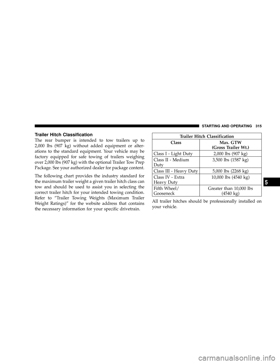
Trailer Hitch Classification
The rear bumper is intended to tow trailers up to
2,000 lbs (907 kg) without added equipment or alter-
ations to the standard equipment. Your vehicle may be
factory equipped for safe towing of trailers weighing
over 2,000 lbs (907 kg) with the optional Trailer Tow Prep
Package. See your authorized dealer for package content.
The following chart provides the industry standard for
the maximum trailer weight a given trailer hitch class can
tow and should be used to assist you in selecting the
correct trailer hitch for your intended towing condition.
Refer to ªTrailer Towing Weights (Maximum Trailer
Weight Ratings)º for the website address that contains
the necessary information for your specific drivetrain.Trailer Hitch Classification
Class Max. GTW
(Gross Trailer Wt.)
Class I - Light Duty 2,000 lbs (907 kg)
Class II - Medium
Duty3,500 lbs (1587 kg)
Class III - Heavy Duty 5,000 lbs (2268 kg)
Class IV - Extra
Heavy Duty10,000 lbs (4540 kg)
Fifth Wheel/
GooseneckGreater than 10,000 lbs
(4540 kg)
All trailer hitches should be professionally installed on
your vehicle.
STARTING AND OPERATING 315
5