oil temperature DODGE DART 2013 PF / 1.G User Guide
[x] Cancel search | Manufacturer: DODGE, Model Year: 2013, Model line: DART, Model: DODGE DART 2013 PF / 1.GPages: 132, PDF Size: 4.13 MB
Page 8 of 132
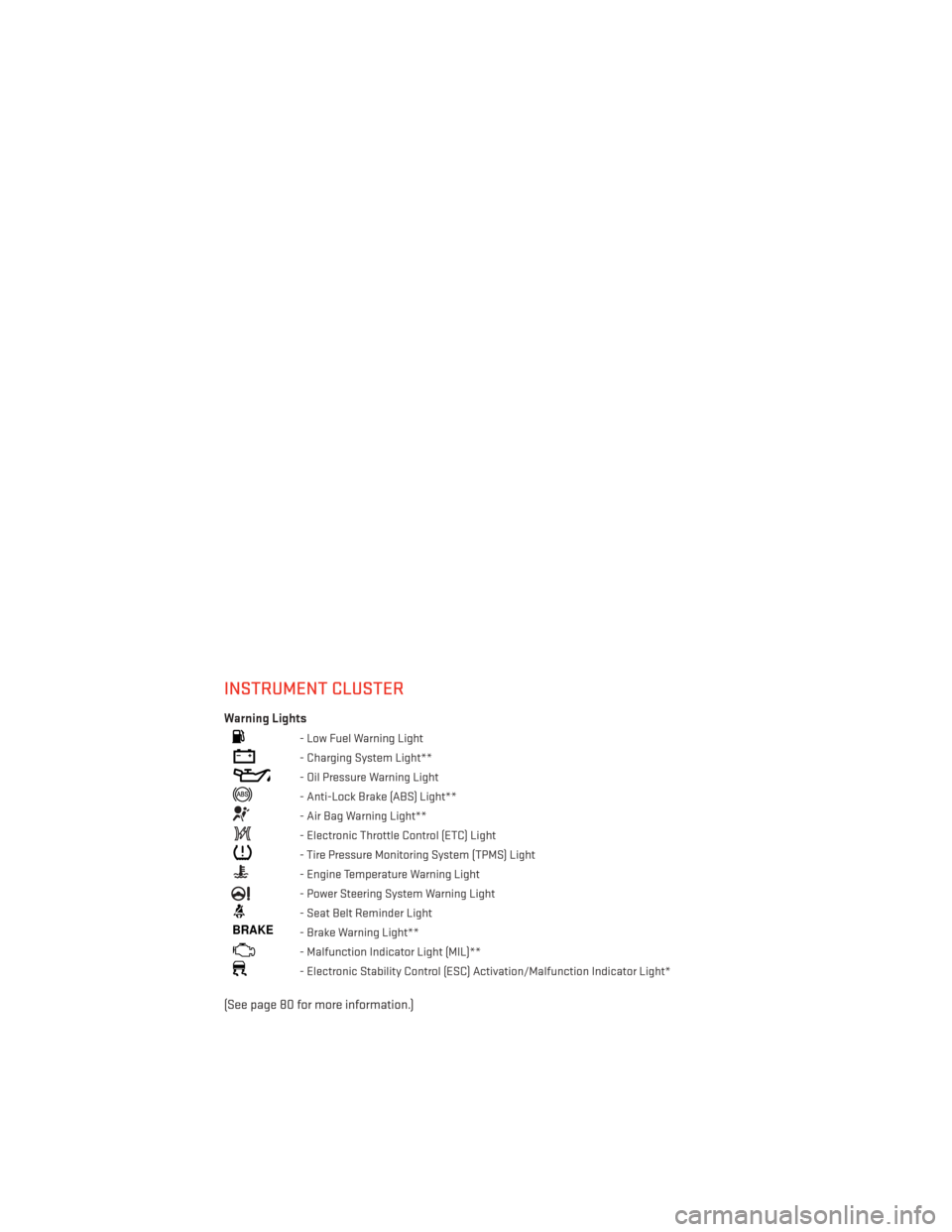
INSTRUMENT CLUSTER
Warning Lights
- Low Fuel Warning Light
- Charging System Light**
- Oil Pressure Warning Light
- Anti-Lock Brake (ABS) Light**
- Air Bag Warning Light**
- Electronic Throttle Control (ETC) Light
- Tire Pressure Monitoring System (TPMS) Light
- Engine Temperature Warning Light
- Power Steering System Warning Light
- Seat Belt Reminder Light
BRAKE- Brake Warning Light**
- Malfunction Indicator Light (MIL)**
- Electronic Stability Control (ESC) Activation/Malfunction Indicator Light*
(See page 80 for more information.)
CONTROLS AT A GLANCE
6
Page 75 of 132
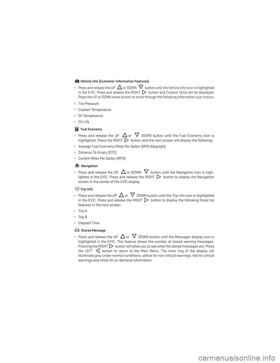
Vehicle Info (Customer Information Features)
•Press and release the UPor DOWNbutton until the Vehicle Info icon is highlighted
in the EVIC. Press and release the RIGHT
button and Coolant Temp will be displayed.
Press the UP or DOWN arrow button to scroll through the following information sub-menus:
• Tire Pressure
• Coolant Temperature
• Oil Temperature
• Oil Life
Fuel Economy
• Press and release the UPorDOWN button until the Fuel Economy icon is
highlighted. Press the RIGHT
button and the next screen will display the following:
• Average Fuel Economy/Miles Per Gallon (MPG Bargraph)
• Distance To Empty (DTE)
• Current Miles Per Gallon (MPG)
Navigation
• Press and release the UPor DOWNbutton until the Navigation icon is high-
lighted in the EVIC. Press and release the RIGHT
button to display the Navigation
screen in the center of the EVIC display.
Trip Info
• Press and release the UPorDOWN button until the Trip Info icon is highlighted
in the EVIC. Press and release the RIGHT
button to display the following three trip
features in the next screen:
• Trip A
• Trip B
• Elapsed Time
Stored Message
• Press and release the UPorDOWN button until the Messages display icon is
highlighted in the EVIC. This feature shows the number of stored warning messages.
Pressing the RIGHT
button will allow you to see what the stored messages are. Press
the LEFT
button to return to the Main Menu. The inner ring of the display will
illuminate grey under normal conditions, yellow for non critical warnings, red for critical
warnings and white for on demand information.
ELECTRONICS
73
Page 83 of 132
• Your vehicle has also been equipped with a TPMS malfunction indicator to indicate whenthe system is not operating properly. The TPMS malfunction indicator is combined with
the low tire pressure telltale. When the system detects a malfunction, the telltale will
flash for approximately one minute and then remain continuously illuminated. This
sequence will continue each time the vehicle is restarted as long as the malfunction
exists.
• When the malfunction indicator is illuminated, the system may not be able to detect or signal low tire pressure as intended. TPMS malfunctions may occur for a variety of
reasons, including the installation of replacement or alternate tires or wheels on the
vehicle that prevent the TPMS from functioning properly. Always check the TPMS mal-
function telltale after replacing one or more tires or wheels on your vehicle, to ensure that
the replacement or alternate tires and wheels allow the TPMS to continue to function
properly.
NOTE:
Tire pressures change by approximately 1 psi (7 kPa) per 12° F (7° C) of air temperature
change. Keep this in mind when checking tire pressure inside a garage, especially in the
Winter. Example: If garage temperature is 68°F (20°C) and the outside temperature is 32°F
(0°C), then the cold tire inflation pressure should be increased by 3 psi (21 kPa), which equals
1 psi (7 kPa) for every 12°F (7°C) for this outside temperature condition.
CAUTION!
The TPMS has been optimized for the original equipment tires and wheels. TPMS
pressures and warning have been established for the tire size equipped on your vehicle.
Undesirable system operation or sensor damage may result when using replacement
equipment that is not of the same size, type, and/or style. Aftermarket wheels can cause
sensor damage. Do not use tire sealant from a can, or balance beads if your vehicle is
equipped with a TPMS, as damage to the sensors may result.
- Engine Temperature Warning Light
• This light warns of an overheated engine condition.
• If the light turns on or flashes continuously while driving, safely pull over and stop the vehicle. If the A/C system is on, turn it off. Also, shift the transmission into NEUTRAL and
idle the vehicle. If the temperature reading does not return to normal, turn the engine off
immediately.
• We recommend that you do not operate the vehicle or engine damage will occur. Have the vehicle serviced immediately.
WARNING!
A hot engine cooling system is dangerous. You or others could be badly burned by steam
or boiling coolant.
WHAT TO DO IN EMERGENCIES
81
Page 112 of 132
CAUTION!
• Mixing of engine coolant (antifreeze) other than specified Organic Additive Technol-ogy (OAT) engine coolant (antifreeze), may result in engine damage and may de-
crease corrosion protection. Organic Additive Technology (OAT) engine coolant is
different and should not be mixed with Hybrid Organic Additive Technology (HOAT)
engine coolant (antifreeze) or any “globally compatible” coolant (antifreeze). If a
non-OAT engine coolant (antifreeze) is introduced into the cooling system in an
emergency, the cooling system will need to be drained, flushed, and refilled with
fresh OAT coolant (conforming to MS-12106), by an authorized dealer as soon as
possible.
• Do not use water alone or alcohol-based engine coolant (antifreeze) products. Do not
use additional rust inhibitors or antirust products, as they may not be compatible
with the radiator engine coolant and may plug the radiator.
• This vehicle has not been designed for use with propylene glycol-based engine
coolant (antifreeze). Use of propylene glycol-based engine coolant (antifreeze) is not
recommended.
MAINTENANCE SCHEDULE
Your vehicle is equipped with an automatic oil change indicator system. The oil change
indicator system will remind you that it is time to take your vehicle in for scheduled
maintenance.
Based on engine operation conditions, the oil change indicator message will illuminate.
This means that service is required for your vehicle. Operating conditions such as frequent
short-trips, trailer tow, extremely hot or cold ambient temperatures, and E85 fuel usage will
influence when the “Change Oil” or “Oil Change Required” message is displayed. Severe
Operating Conditions can cause the change oil message to illuminate as early as 3,500
miles (5,600 km) since last reset. Have your vehicle serviced as soon as possible, within the
next 500 miles (805 km).
NOTE:
Under no circumstances should oil change intervals exceed 10,000 miles (16,000 km) or
twelve months, whichever comes first.
MAINTAINING YOUR VEHICLE
110
Page 117 of 132
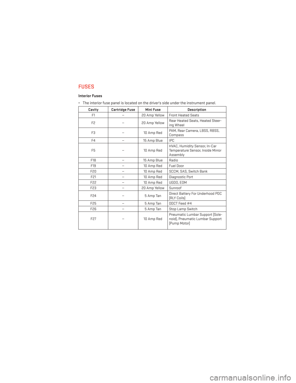
FUSES
Interior Fuses
• The interior fuse panel is located on the driver's side under the instrument panel.
Cavity Cartridge Fuse Mini FuseDescription
F1 — 20 Amp Yellow Front Heated Seats
F2 — 20 Amp Yellow Rear Heated Seats, Heated Steer-
ing Wheel
F3 — 10 Amp Red PAM, Rear Camera, LBSS, RBSS,
Compass
F4 — 15 Amp Blue IPC
F5 — 10 Amp Red HVAC, Humidity Sensor, In-Car
Temperature Sensor, Inside Mirror
Assembly
F18 — 15 Amp Blue Radio
F19 — 10 Amp Red Fuel Door
F20 — 10 Amp Red SCCM, SAS, Switch Bank
F21 — 10 Amp Red Diagnostic Port
F22 — 10 Amp Red UGDO, EOM
F23 — 20 Amp Yellow Sunroof
F24 —5 Amp Tan Direct Battery For Underhood PDC
(RLY Coils)
F25 —5 Amp Tan DDCT Feed #4
F26 —5 Amp Tan Stop Lamp Switch
F27 — 10 Amp Red Pneumatic Lumbar Support (Sole-
noid), Pneumatic Lumbar Support
(Pump Motor)
MAINTAINING YOUR VEHICLE
115
Page 125 of 132
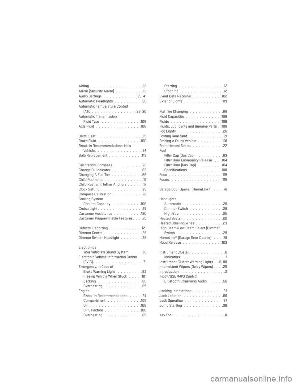
Airbag...................16
Alarm (Security Alarm)..........13
Audio Settings ............39,41
Automatic Headlights ..........26
Automatic Temperature Control (ATC)................29,30
Automatic Transmission Fluid Type ..............108
AxleFluid................108
Belts, Seat .................15
BrakeFluid................108
Break-In Recommendations, New Vehicle .................24
BulbReplacement........... .119
Calibration, Compass ...........72
Change Oil Indicator ...........83
Changing A Flat Tire ...........86
Child Restraint ...............17
Child Restraint Tether Anchors ......17
Clock Setting ...............39
Compass Calibration ...........72
Cooling System Coolant Capacity ..........108
Cruise Light ................27
Customer Assistance ..........120
Customer Programmable Features ....75
Defects, Reporting ............121
Dimmer Control ..............26
Dimmer Switch, Headlight ........26
Electronics Your Vehicle's Sound System ....36
Electronic Vehicle Information Center (EVIC)..................71
Emergency, In Case of Brake Warning Light .........82
Freeing Vehicle When Stuck .....101
Jacking ................86
Overheating .............85
Engine Break-In Recommendations .....24
Compartment ............105
Oil ..................108
Oil Selection .............108
Overheating .............85 Starting ................12
Stopping
...............12
EventDataRecorder...........102
Exterior Lights ..............119
FlatTireChanging ............86
Fluid Capacities .............108
Fluids ..................108
Fluids, Lubricants and Genuine Parts . .108
FogLights ................26
Folding Rear Seat .............21
Freeing A Stuck Vehicle .........101
Front Heated Seats ............22
Fuel Filler Cap (Gas Cap) .........83
Filler Door Emergency Release . . .104
Filler Door (Gas Cap) .........104
Specifications ............108
Fuse ...................115
Fuses.................. .115
Garage Door Opener (HomeLink®) ....76
Headlights Automatic ..............
26
Dimmer Switch ............26
HighBeam ..............25
Heated Seats ...............22
Heated Steering Wheel ..........23
High Beam/Low Beam Select (Dimmer) Switch .................25
HomeLink® (Garage Door Opener) ....76
Hood Release ..............103
Instrument Cluster .............6
Indicators ...............7
Instrument Cluster Warning Lights . .6, 80
Intermittent Wipers (Delay Wipers) ....25
Introduction ................2
iPod®/USB/MP3 Control Bluetooth Streaming Audio .....56
Jacking Instructions ...........87
Jack Location ..............86
Jack Operation ..............87
Jump Starting ..............98
KeyFob...................8
INDEX
123