ECU DODGE DART 2014 PF / 1.G User Guide
[x] Cancel search | Manufacturer: DODGE, Model Year: 2014, Model line: DART, Model: DODGE DART 2014 PF / 1.GPages: 140, PDF Size: 4.57 MB
Page 3 of 140

INTRODUCTION/WELCOME
WELCOME FROM CHRYSLER GROUP LLC . . . 2
CONTROLS AT A GLANCE
DRIVER COCKPIT................4
INSTRUMENT CLUSTER ............6
GETTING STARTED
KEYFOB .....................8
REMOTE START.................9
KEYLESS ENTER-N-GO™ ...........10
VEHICLE SECURITY ALARM ..........13
SEATBELT ...................15
SUPPLEMENTAL RESTRAINT SYSTEM (SRS) —
AIRBAGS ....................15
CHILD RESTRAINTS ..............17
FRONT SEATS .................20
REARSEAT ..................22
HEATEDSEATS ................22
TILT/TELESCOPING STEERING COLUMN . . . 23
HEATED STEERING WHEEL ..........24
OPERATING YOUR VEHICLE
ENGINE BREAK-IN RECOMMENDATIONS . . . 25
TURN SIGNAL/WIPER/WASHER/HIGH BEAM
LEVER......................25
HEADLIGHT SWITCH ..............27
SPEED CONTROL ................28
MANUAL CLIMATE CONTROLS ........30
Uconnect® 8.4 MANUAL CLIMATE
CONTROLS ...................31
Uconnect® 8.4 AUTOMATIC CLIMATE
CONTROLS ...................32
POWER SUNROOF ...............34
WIND BUFFETING ...............35
SIX-SPEED AUTOMATIC TRANSMISSION . . . 35
ELECTRONICS
YOUR VEHICLE'S SOUND SYSTEM ......38
Uconnect® 200 .................40
Uconnect® 8.4 & 8.4N .............49
STEERING WHEEL AUDIO CONTROLS ....72
ELECTRONIC VEHICLE INFORMATION CENTER
(EVIC) — STANDARD (2 BUTTON) ........73
ELECTRONIC VEHICLE INFORMATION CENTER
(EVIC) — PREMIUM (4 BUTTON) ........74
UNIVERSAL GARAGE DOOR OPENER
(HomeLink®) ..................78
POWER OUTLET ................81
UTILITY
TRAILER TOWING WEIGHTS (MAXIMUM
TRAILERWEIGHTRATINGS) .........82
RECREATIONAL TOWING (BEHIND
MOTORHOME, ETC.) ..............82
WHAT TO DO IN EMERGENCIES
ROADSIDE ASSISTANCE ............83INSTRUMENT CLUSTER WARNING LIGHTS..83
IF YOUR ENGINE OVERHEATS .........88
JACKING AND TIRE CHANGING ........89
TIREFIT KIT ...................95
JUMP-STARTING ...............101
SHIFT LEVER OVERRIDE ...........103
TOWING A DISABLED VEHICLE .......104
FREEING A STUCK VEHICLE .........104
EVENT DATA RECORDER (EDR) ........105
MAINTAINING YOUR VEHICLE
OPENING THE HOOD.............106
FUEL DOOR RELEASE ............107
ENGINE COMPARTMENT ...........108
FLUIDS AND CAPACITIES ...........111
MAINTENANCE SCHEDULE ..........113
MAINTENANCE RECORD ...........116
FUSES .....................117
TIRE PRESSURES ...............119
WHEEL AND WHEEL TRIM CARE ......120
EXTERIOR BULBS ...............121
CONSUMER ASSISTANCE
CHRYSLER GROUP LLC CUSTOMER
CENTER....................122
CHRYSLER CANADA INC. CUSTOMER
CENTER ....................122
ASSISTANCE FOR THE HEARING
IMPAIRED ...................122
PUBLICATIONS ORDERING ..........122
REPORTING SAFETY DEFECTS IN THE
UNITEDSTATES ................123
Uconnect® CUSTOMER CENTER .......123
MOPAR® ACCESSORIES
AUTHENTIC ACCESSORIES BY MOPAR® . . 124
FAQ (How To?)
FREQUENTLY ASKED QUESTIONS ......125
INDEX....................127
TABLE OF CONTENTS
Page 9 of 140
5. Gear Position Display
6. Fuel Gauge
7. Fuel Door Location
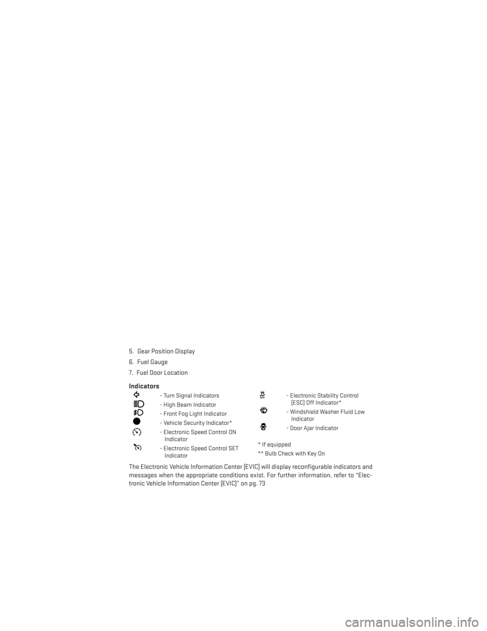
Indicators
- Turn Signal Indicators
- High Beam Indicator
- Front Fog Light Indicator
- Vehicle Security Indicator*
- Electronic Speed Control ONIndicator
- Electronic Speed Control SETIndicator
- Electronic Stability Control(ESC) Off Indicator*
- Windshield Washer Fluid LowIndicator
- Door Ajar Indicator
* If equipped
** Bulb Check with Key On
The Electronic Vehicle Information Center (EVIC) will display reconfigurable indicators and
messages when the appropriate conditions exist. For further information, refer to “Elec-
tronic Vehicle Information Center (EVIC)” on pg. 73
CONTROLS AT A GLANCE
7
Page 11 of 140
Emergency Key
• Should the battery in the vehicle or the Key Fob transmitter go dead, there is anemergency key located in the Key Fob. To remove the emergency key, slide the button at
the back of the Key Fob sideways with your thumb and then pull the key out with your
other hand.
• The emergency key is also for locking the glove compartment.
WARNING!
• Never leave children alone in a vehicle, or with access to an unlocked vehicle. Allowing children to be in a vehicle unattended is dangerous for a number of reasons.
A child or others could be seriously or fatally injured. Children should be warned not
to touch the parking brake, brake pedal or the shift lever.
• Do not leave the Key Fob in or near the vehicle, or in a location accessible to children,
and do not leave the ignition of a vehicle equipped with Keyless Enter-N-Go™ in the
ACC or ON/RUN mode. A child could operate power windows, other controls, or move
the vehicle.
REMOTE START
• Press the REMOTE START buttonx2on the Key Fob twice within five seconds. Pressing
the REMOTE START button a third time shuts the engine off.
• To drive the vehicle, press the UNLOCK button and cycle the ignition to the ON/RUN position.
• With remote start, the engine will only run for 15 minutes (timeout) unless the ignition is cycled to the ON/RUN position.
• The vehicle must be cycled to the ON/RUN position after two consecutive timeouts.
WARNING!
• Do not start or run an engine in a closed garage or confined area. Exhaust gas contains Carbon Monoxide (CO) which is odorless and colorless. Carbon Monoxide is
poisonous and can cause you or others to be severely injured or killed when inhaled.
• Keep Key Fob transmitters away from children. Operation of the Remote Start
System, windows, door locks or other controls could cause you and others to be
severely injured or killed.
GETTING STARTED
9
Page 15 of 140
Starting With The Ignition Switch In The OFF Position:
• Press the ENGINE START/STOP button once to change the ignition switch to the ACCposition.
• Press the ENGINE START/STOP button a second time to change the ignition switch to the ON/RUN position.
• Press the ENGINE START/STOP button a third time to return the ignition switch to the OFF position.
NOTE:
If the ignition switch is left in the ACC or
ON/RUN (engine not running) position and
the transmission is in PARK, the system will
automatically time out after 30 minutes of
inactivity and the ignition will switch to the
OFF position.
VEHICLE SECURITY ALARM
To Arm The System
Vehicles Not Equipped With Keyless Enter-N-Go™
Remove the key from the ignition switch and either press a power door LOCK switch while
the driver or passenger door is open or press the LOCK button on the Remote Keyless Entry
(RKE) transmitter. After the last door is closed, or if all doors are closed, the Vehicle Security
Alarm will arm itself in about 16 seconds. During that time, the Vehicle Security Light will
flash. If it does not illuminate, the Vehicle Security Alarm is not arming. In addition, if you
open a door during the arming period, the Vehicle Security Alarm will cancel the arming
process. If you wish to rearm the Vehicle Security Alarm after closing the door, you must
repeat one of the previously-described arming sequences.
You may also disarm the ultrasonic intrusion sensor during the 16 second arming period by
pressing the lock button three times with a delay of no more than five seconds between key
presses. The horn will pulse twice to acknowledge that the ultrasonic intrusion sensor has
been disabled.
NOTE:
• The driver’s door key cylinder and the trunk button on the RKE transmitter cannot arm or disarm the Vehicle Security Alarm.
• The Vehicle Security Alarm remains armed during trunk entry. Pressing the TRUNK button will not disarm the Vehicle Security Alarm. If someone enters the vehicle through
the trunk, and opens any door, the alarm will sound.
GETTING STARTED
13
Page 16 of 140
• When the Vehicle Security Alarm is armed, the interior power door lock switches will notunlock the doors.
• The ultrasonic intrusion sensor may be inadvertently activated by a child, pet or shifting package left within the vehicle after the Vehicle Security Alarm is armed.
Vehicles Equipped With Keyless Enter-N-Go™
Press the Keyless Enter-N-Go™ START/STOP button until the Electronic Vehicle Information
Center (EVIC) indicates that the vehicle ignition is “OFF” (refer to “Starting Procedures” in
“Starting And Operating” for further information). Then either press the power door LOCK
switch while the driver or passenger door is open, press the Remote Keyless Entry (RKE)
transmitter LOCK button or press the Passive Entry Door Handle LOCK button (refer to “Keyless
Enter-N-Go™” in “Things To Know Before Starting Your Vehicle” for further information).
To Disarm The System
The Vehicle Security Alarm is designed to protect your vehicle; however, you can create
conditions where the Vehicle Security Alarm will give you a false alarm. If one of the
previously-described arming sequences has occurred, the Vehicle Security Alarm will arm
regardless of whether you are in the vehicle or not. If you remain in the vehicle and open a
door, the alarm will sound. If this occurs, disarm the Vehicle Security Alarm.
If the Vehicle Security Alarm is armed and the battery becomes disconnected the Vehicle
Security Alarm will remain armed when the battery is reconnected. The exterior lights will
flash, and the horn will sound. If this occurs, disarm the Vehicle Security Alarm.
Vehicles Not Equipped With Keyless Enter-N-Go™
Either press the UNLOCK button on the RKE transmitter or insert a valid ignition key into the
ignition switch and turn the key to the ON/RUN position.
NOTE:
• The driver's door key cylinder and the trunk button on the RKE transmitter cannot arm ordisarm the Vehicle Security Alarm.
• The Vehicle Security Alarm remains armed during trunk entry. Pressing the TRUNK button will not disarm the Vehicle Security Alarm. If someone enters the vehicle through
the trunk, and opens any door, the alarm will sound.
• When the Vehicle Security Alarm is armed, the interior power door lock switches will not unlock the doors.
Vehicles Equipped With Keyless Enter-N-Go™
Either press the UNLOCK button on the RKE transmitter or grasp the Passive Entry Unlock
Door Handle (refer to “Keyless Enter-N-Go™” in “Things To Know Before Starting Your
Vehicle” for further information), press the Keyless Enter-N-Go™ START/STOP button (re-
quires at least one valid Key Fob in the vehicle), or insert a valid Key Fob into the ignition
switch (if the START/STOP button is removed) and rotate it to the ON/RUN position.
GETTING STARTED
14
Page 17 of 140
Tamper Alert
If something has triggered the Vehicle Security Alarm in your absence, the horn will sound
three times and the exterior lights will blink three times when you disarm the Vehicle
Security Alarm. Check the vehicle for tampering.
SEAT BELT
Be sure everyone in your vehicle is in a seat and using a seat belt properly.
•
Position the lap belt across your thighs, below your abdomen. To remove slack in the lap
portion, pull up a bit on the shoulder belt. To loosen the lap belt if it is too tight, tilt the latch
plate and pull on the lap belt. A snug belt reduces the risk of sliding under the belt in a collision.
• Position the shoulder belt on your chest so that it is comfortable and not resting on your neck. The retractor will withdraw any slack in the belt.
A shoulder belt placed behind you will not protect you from injury during a collision. You are
more likely to hit your head in a collision if you do not wear your shoulder belt. The lap and
shoulder belt are meant to be used together.
A belt that is too loose will not protect you properly. In a sudden stop you could move too far
forward, increasing the possibility of injury. Wear your seat belt snugly.
A frayed or torn belt could rip apart in a collision and leave you with no protection. Inspect the
belt system periodically, checking for cuts, frays, or loose parts. Damaged parts must be
replaced immediately. Do not disassemble or modify the system. Seat belt assemblies must be
replaced after a collision if they have been damaged (bent retractor, torn webbing, etc.).
The seat belts for both front seating positions are equipped with pretensioning devices that
are designed to remove slack from the seat belt in the event of a collision.
A deployed pretensioner or a deployed air bag must be replaced immediately.
WARNING!
In a collision, you and your passengers can suffer much greater injuries if you are not
properly buckled up. You can strike the interior of your vehicle or other passengers, or you
can be thrown out of the vehicle. Always be sure you and others in your vehicle are
buckled up properly.
SUPPLEMENTAL RESTRAINT SYSTEM (SRS) — AIR BAGS
• This vehicle has Advanced Front Air Bags for both the driver and right front passenger as a supplement to the seat belt restraint system. The Advanced Front Air Bags will not
deploy in every type of collision.
• Advanced Front Air Bags are designed to provide additional protection by supplementing the seat belts in certain frontal collisions depending on several factors, including the
severity and type of collision. Advanced Front Air Bags are not expected to reduce the
risk of injury in rear, side, or rollover collisions.
GETTING STARTED
15
Page 19 of 140
CHILD RESTRAINTS
Children 12 years or younger should ride properly buckled up in a rear seat, if available.
According to crash statistics, children are safer when properly restrained in the rear seats
rather than in the front.
Every state in the United States and all Canadian provinces require that small children ride
in proper restraint systems. This is the law, and you can be prosecuted for ignoring it.
NOTE:
• For additional information, refer to www.seatcheck.org or call 1–866–SEATCHECK(1–866–732–8243).
• Canadian residents, should refer to Transport Canada’s website for additional informa- tion: http://www.tc.gc.ca/eng/roadsafety/safedrivers-childsafety-index-53.htm
LATCH — Lower Anchors And Tethers For CHildren
• Your vehicle is equipped with the child restraint anchorage system called LATCH, whichstands for Lower Anchors and Tethers for CHildren.
• The rear outboard seating positions have lower anchors and top tether anchors.
The rear center seating position has a top
tether anchor only.
• You may use the LATCH anchorage sys- tem until the combined weight of the
child and the child restraint is 65 lbs
(29.5 kg). Use the seat belt and tether
anchor instead of the LATCH system once
the combined weight is more than 65 lbs
(29.5 kg).
•
The lower anchorages are round bars that are found at the rear of the seat cushion
where it meets the seatback, below the anchorage symbols on the seatback. They are
just visible when you lean into the rear seat to install the child restraint. You will easily feel
them if you run your finger along the gap between the seatback and seat cushion.
GETTING STARTED
17
Page 21 of 140
To Install A Child Seat Using An ALR:
1. Pull enough of the seat belt webbing from the retractor to pass it through the belt path ofthe child restraint. Do not twist the belt webbing in the belt path.
2. Slide the latch plate into the buckle until you hear a “click.”
3. Pull on the webbing to make the lap portion tight against the child seat.
4. To lock the seat belt, pull down on the shoulder part of the belt until you have pulled all the seat belt webbing out of the retractor. Then, allow the webbing to retract back into the
retractor. As the webbing retracts, you will hear a clicking sound. This means the seat
belt is now in the Automatic Locking mode.
5. Try to pull the webbing out of the retractor. If it is locked, you should not be able to pull out any webbing. If the retractor is not locked, repeat the last step.
6. Finally, pull up on any extra webbing to tighten the lap portion around the child restraint while you push the child restraint rearward and downward into the vehicle seat.
7. If the child restraint has a top tether strap and the seating position has a top tether anchorage, connect the tether strap to the anchorage and tighten the tether strap. See
below for directions to attach a tether anchor.
8. Test that the child restraint is installed tightly by pulling back and forth on the child seat at the belt path. It should not move more than 1 inch (25.4 mm) in any direction.
Installing The Top Tether Strap (With Either Lower Anchors Or Vehicle
Seat Belt):
When installing a forward-facing child restraint, always secure the top tether strap, up to
the tether anchor weight limit, whether the child restraint is installed with the lower anchors
or the vehicle seat belt.
1. Rotate or lift the cover to access the anchor directly behind the seat where you areplacing the child restraint.
2. Route the tether strap to provide the most direct path for the strap between the anchor and the child seat.
3. If your vehicle is equipped with adjustable rear head restraints, raise the head restraint, and where possible, route the tether strap under the head restraint and between the two
posts. If not possible, lower the head restraint and pass the tether strap around the
outboard side of the head restraint.
4. Attach the tether strap hook of the child restraint to the top tether anchorage and remove slack in the tether strap according to the child restraint manufacturer’s instruc-
tions.
GETTING STARTED
19
Page 22 of 140
WARNING!
• In a collision, an unrestrained child, even a tiny baby, can become a projectile insidethe vehicle. The force required to hold even an infant on your lap could become so
great that you could not hold the child, no matter how strong you are. The child and
others could be severely injured or killed. Any child riding in your vehicle should be in
a proper restraint for the child's size.
• Rearward-facing child seats must never be used in the front seat of a vehicle with a
front passenger air bag. An air bag deployment could cause severe injury or death to
infants in this position.
• Only use a rearward-facing child restraint in a vehicle with a rear seat.
• Improper installation of a child restraint to the LATCH anchorages can lead to failure
of an infant or child restraint. The child could be severely injured or killed. Follow the
manufacturer’s directions exactly when installing an infant or child restraint.
• An incorrectly anchored tether strap could lead to increased head motion and
possible injury to the child. Use only the anchor positions directly behind the child
seat to secure a child restraint top tether strap.
• If your vehicle is equipped with a split rear seat, make sure the tether strap does not
slip into the opening between the seatbacks as you remove slack in the strap.
FRONT SEATS
Power Seats
•The power seat switches are located on the
outboard side of the front seat cushions.
• The power seat switch controls forward/ back, up/down and tilt adjustment.
• The recline switch controls the angle of the seatback. Press the switch forward or
rearward and the seatback will move in
either direction.
Power Lumbar
• Push the switch forward to increase thelumbar support. Push the switch rearward
to decrease the lumbar support.
• Pushing upward or downward on the switch will raise and lower the position of the support.
GETTING STARTED
20
Page 24 of 140
REAR SEAT
Folding Rear Seatback
• Pull on the loops, located near the outertop of the seatbacks, to fold down either
or both seatbacks. These loops can be
tucked away when not in use.
• When the seatback is raised to the upright position, make sure it is latched by
strongly pulling on the top of the seatback
above the seat loop.
WARNING!
• Be certain that the seatback is securely locked into position. If the seatback is not
securely locked into position, the seat will not provide the proper stability for child
seats and/or passengers. An improperly latched seat could cause you and others to
severely injured or killed.
• The cargo area in the rear of the vehicle (with the rear seatbacks in the locked-up or
folded-down position) should not be used as a play area by children when the vehicle
is in motion. They could be severely injured or killed in a collision. Children should be
seated and using the proper restraint system.
HEATED SEATS
Front Heated Seats
The front heated seats control buttons are located within the climate or controls screen of
the touchscreen.
• Press the heated seat button
once to turn the High setting On.
• Press the heated seat button
a second time to turn the Low setting On.
• Press the heated seat button
a third time to turn the heating elements Off.
If the High-level setting is selected, the system will automatically switch to Low-level after
approximately 60 minutes. The Low-level setting will turn Off automatically after approxi-
mately 45 minutes.
GETTING STARTED
22