turn signal DODGE DART 2015 PF / 1.G Owner's Manual
[x] Cancel search | Manufacturer: DODGE, Model Year: 2015, Model line: DART, Model: DODGE DART 2015 PF / 1.GPages: 664, PDF Size: 16.96 MB
Page 339 of 664
•Service Tire Pressure System
•Parking Brake Engaged
•Brake Fluid Low
•Service Electronic Braking System
•Engine Temperature Hot
•Service Electronic Throttle Control
•Lights On
•Right Turn Signal Light Out
•Left Turn Signal Light Out
•Turn Signal On
•Vehicle Not In Park
•Key In Ignition
•Key In Ignition Lights On
•Remote Start Active Key to Run
•Remote Start Active Push Start Button
•Remote Start Aborted Fuel Low
•Remote Start Aborted Too Cold
•Remote Start Aborted Door Open
•Remote Start Aborted Hood Open
•Remote Start Aborted Trunk Open
•Remote Start Aborted Time Expired
•Remote Start Disabled Start to Reset
•Service Airbag System
•Service Airbag Warning Light
•Driver Seatbelt Unbuckled
•Passenger Seatbelt Unbuckled
4
UNDERSTANDING YOUR INSTRUMENT PANEL 337
Page 358 of 664
•Show Time In Status Bar — If Equipped
When in this display, you may turn on or shut off the
digital clock in the status bar. To change the Show Time
Status setting press the “Show Time in Status Bar” button
on the touchscreen until a check-mark appears next to
setting, indicating that the setting has been selected. Press
the back arrow button on the touchscreen to return to the
previous menu.
Safety & Driving Assistance
After pressing the Safety/Assistance button on the touch-
screen the following settings will be available.
•Park Assist — If Equipped
The Rear Park Assist system will scan for objects behind
the vehicle when the transmission shift lever is in RE-
VERSE and the vehicle speed is less than 11 mph
(18 km/h). The system can be enabled with Sound Only,
Sound and Display, or turned OFF. To change the Park
Assist status, press and release the OFF, Sound Only or
Sounds and Display button. Then press the back arrow
button on the touchscreen. Refer to “ParkSense® Rear
Park Assist” in “Understanding The Features Of Your
Vehicle” for system function and operating information.
•Blind Spot Alert — If Equipped
When this feature is selected, the Blind Spot Alert feature
can be set to Off, Lights or Lights and Chime. The Blind
Spot Alert feature can be activated in “Lights” mode.
When this mode is selected, the Blind Spot Monitor
(BSM) system is activated and will only show a visual
alert in the outside mirrors. When “Lights & Chime”
mode is activated, the Blind Spot Monitor (BSM) will
show a visual alert in the outside mirrors as well as an
audible alert when the turn signal is on. When “Off” is
selected, the Blind Spot Monitor (BSM) system is deacti-
vated. To change the Blind Spot Alert status, press the
Off, Lights or Lights & Chime button on the touchscreen.
Then press the back arrow button on the touchscreen.
356 UNDERSTANDING YOUR INSTRUMENT PANEL
Page 456 of 664
WARNING!
•The ABS contains sophisticated electronic equip-
ment that may be susceptible to interference
caused by improperly installed or high output
radio transmitting equipment. This interference
can cause possible loss of anti-lock braking capa-
bility. Installation of such equipment should be
performed by qualified professionals.
•Pumping of the Anti-Lock Brakes will diminish
their effectiveness and may lead to a collision.
Pumping makes the stopping distance longer. Just
press firmly on your brake pedal when you need to
slow down or stop.
(Continued)
WARNING!(Continued)
•The ABS cannot prevent the natural laws of phys-
ics from acting on the vehicle, nor can it increase
braking or steering efficiency beyond that afforded
by the condition of the vehicle brakes and tires or
the traction afforded.
•The ABS cannot prevent collisions, including those
resulting from excessive speed in turns, following
another vehicle too closely, or hydroplaning.
•The capabilities of an ABS equipped vehicle must
never be exploited in a reckless or dangerous
manner that could jeopardize the user’s safety or
the safety of others.
All vehicle wheels and tires must be the same size and
type and tires must be properly inflated to produce
accurate signals for the computer.
454 STARTING AND OPERATING
Page 497 of 664
Tire Pressure Monitoring Low Pressure Warnings
The Tire Pressure Monitoring Telltale Light will illumi-
nate in the instrument cluster, a#LOW TIRE PRESSURE#
message and “Inflate Tire to XX” message will be dis-
played for a minimum of five seconds, and an audible
chime will be activated when one or more of the four
active road tire pressures are low. Should this occur, you
should stop as soon as possible, check the inflation
pressure of each tire on your vehicle, and inflate each tire
to the vehicle’s recommended cold placard pressure
value. The recommended cold placard pressure value is
the pressure value in the#Inflate Tire to XX#message
displayed in the EVIC/DID. The system will automati-
cally update and the Tire Pressure Monitoring Light will
extinguish and the#LOW TIRE PRESSURE#and “Inflate
Tire to XX” messages will turn off once the updated tire
pressures have been received. The vehicle may need to be
driven for up to 20 minutes above 15 mph (24 km/h) to
receive this information.
Service TPMS Warnings
The Tire Pressure Monitoring Telltale Light will flash on
and off for 75 seconds and then remain on solid when a
system fault is detected. The system fault will also sound
a chime and display a “SERVICE TPM SYSTEM” mes-
sage for a minimum of five seconds. If the ignition key is
cycled, this sequence will repeat providing the system
fault still exists. The Tire Pressure Monitoring Telltale
Light will turn off when the fault condition no longer
exists. A system fault can occur with any of the following
scenarios:
1. Jamming due to electronic devices or driving next to
facilities emitting the same radio frequencies as the
TPM sensors.
2. Installing some form of aftermarket window tinting
that affects radio wave signals.
3. Snow or ice around the wheels or wheel housings.
5
STARTING AND OPERATING 495
Page 500 of 664
graphic display to the vehicle’s recommended cold plac-
ard pressure value. The system will automatically up-
date, the “Inflate Tire to XX” message will no longer be
displayed, the graphic display of the pressure value(s)
will return to their normal color, and the Tire Pressure
Monitoring Light will extinguish once the updated tire
pressure(s) have been received. The vehicle may need to
be driven for up to 20 minutes above 15 mph (24 km/h)
to receive this information.
Service TPMS Message
The Tire Pressure Monitoring Telltale Light will flash on
and off for 75 seconds, and then remain on solid when a
system fault is detected. The system fault will also sound
a chime. The EVIC/DID will display a “SERVICE TPM
SYSTEM” message for a minimum of five seconds. This
text message is then followed by a graphic display, with
“- -“ in place of the pressure value(s) indicating which
Tire Pressure Monitoring Sensor(s) is not being received.
If the ignition key is cycled, this sequence will repeat,
providing the system fault still exists. If the system fault
no longer exists, the Tire Pressure Monitoring Telltale
Light will no longer flash, the#SERVICE TPM SYSTEM#
message will not be present, and a pressure value will be
displayed instead of dashes. A system fault can occur
with any of the following scenarios:
1. Jamming due to electronic devices or driving next to
facilities emitting the same radio frequencies as the
TPM sensors.
2. Installing some form of aftermarket window tinting
that affects radio wave signals.
3. Snow or ice around the wheels or wheel housings.
4. Using tire chains on the vehicle.
5. Using wheels/tires not equipped with TPM sensors.
498 STARTING AND OPERATING
Page 522 of 664
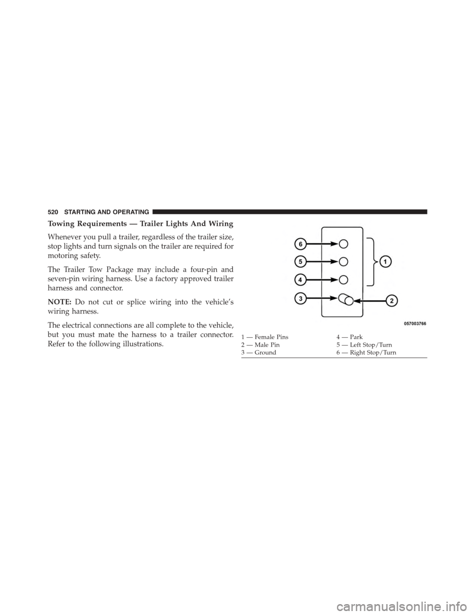
Towing Requirements — Trailer Lights And Wiring
Whenever you pull a trailer, regardless of the trailer size,
stop lights and turn signals on the trailer are required for
motoring safety.
The Trailer Tow Package may include a four-pin and
seven-pin wiring harness. Use a factory approved trailer
harness and connector.
NOTE:Do not cut or splice wiring into the vehicle’s
wiring harness.
The electrical connections are all complete to the vehicle,
but you must mate the harness to a trailer connector.
Refer to the following illustrations.1 — Female Pins4 — Park2 — Male Pin5 — Left Stop/Turn3—Ground6—RightStop/Turn
520 STARTING AND OPERATING
Page 529 of 664
HAZARD WARNING FLASHERS
The Hazard Warning flasher switch is located in the
center of the instrument panel.
Press the switch to turn on the Hazard Warning
flashers. When the switch is activated, all direc-
tional turn signals will flash on and off to warn oncoming
traffic of an emergency. Press the switch a second time to
turn off the Hazard Warning flashers.
This is an emergency warning system and it should not
be used when the vehicle is in motion. Use it when your
vehicle is disabled and it is creating a safety hazard for
other motorists.
When you must leave the vehicle to seek assistance, the
Hazard Warning flashers will continue to operate even
though the ignition is placed in the OFF position.
NOTE:With extended use the Hazard Warning flashers
may wear down your battery.
IF YOUR ENGINE OVERHEATS
In any of the following situations, you can reduce the
potential for overheating by taking the appropriate action.
•On the highways — slow down.
•In city traffic — while stopped, place the transmission in
NEUTRAL, but do not increase the engine idle speed.
NOTE:There are steps that you can take to slow down
an impending overheat condition:
•If your air conditioner (A/C) is on, turn it off. The A/C
system adds heat to the engine cooling system and
turning the A/C off can help remove this heat.
•You can also turn the temperature control to maximum
heat, the mode control to floor and the blower control
to high. This allows the heater core to act as a
supplement to the radiator and aids in removing heat
from the engine cooling system.
6
WHAT TO DO IN EMERGENCIES 527
Page 612 of 664
Exterior Bulbs
Bulb Number
Low Beam/High Beam (Bi-Halogen Headlamp)HIR2
Low Beam/High Beam (Bi-Xenon Headlamp)D3S **
Front Park/Turn Signal Lamp7442NALL
Sidemarker Lamp194
Front Fog LampH11
Center High-Mounted Stop Lamp (CHMSL)LED (Serviced at Authorized Dealer) *
Rear Tail/Stop/Turn Signal LampLED (Serviced at Authorized Dealer) *
Backup Lamp7440
License Lamp168
* Lamp is not serviceable. It is a LED lamp. To replace the
LED, the entire assembly must be replaced.
** The headlamps are a type of high-voltage discharge
tube. High voltage can remain in the circuit even with the
headlamp switch off and the key removed. Because of
this, you should not attempt to service a headlamp bulb
yourself. If a headlamp bulb fails, take your vehicle to an
authorized dealer for service.
610 MAINTAINING YOUR VEHICLE
Page 648 of 664
Entry System, Illuminated....................23
Ethanol................................501
Event Data Recorder........................87
Exhaust Gas Caution.......................111
Exhaust System...........................111
Exterior Folding Mirrors....................123
Exterior Lighting..........................236
Exterior Lights...........................114
Filler Location Fuel........................315
Filters
Air Cleaner...........................575
Air Conditioning.......................405
Automatic Transmission..................595
Engine Oil............................575
Engine Oil Disposal.....................574
Flashers
Hazard Warning........................527
Turn Signal............................114
Flash-To-Pass............................243
Flooded Engine Starting....................415
Floor Console............................293
Fluid, Brake.............................619
Fluid Capacities..........................615
Fluid Leaks.............................114
Fluid Level Checks
Automatic Transmission..................594
Fluids.................................616
Fluids, Lubricants and Genuine Parts...........616
Fog Lights..............................241
Folding Rear Seat.........................232
Freeing A Stuck Vehicle.....................555
Fuel...................................500
Adding..............................505
Additives.............................503
Capacity.............................615
Clean Air.............................501
Ethanol..............................501
646 INDEX
Page 651 of 664
iPod®/USB/MP3 Control
Bluetooth® Streaming Audio...............175
Jacking Instructions........................543
Jack Location............................540
Jack Operation...........................539
Jump Starting............................551
Key Fob
Arm The Alarm.........................20
Keyless Entry...........................38
Lock The Doors.........................25
Panic Alarm............................22
Programming Additional Key Fobs...........27
Programming Additional Transmitters.........27
Remote Keyless Entry (RKE)................23
Unlatch The Trunk.......................26
Unlock The Doors.......................25
Key-In Reminder..........................16
Keyless Enter-N-Go........................412
Keyless Enter-N-Go™
Enter The Trunk.........................26
Key Fob . . . . . . . . . . . . . . . . . . . . . . . . . . . . . . .38
Keyless Enter-N-Go™.....................38
Lock The Vehicle’s Doors..................25
Passive Entry...........................38
Passive Entry Programming.................38
Remote Control.........................38
Unlock From The Driver’s Side..............25
Unlock From The Passenger Side.............25
Keyless Entry System.......................23
Keyless Go...............................13
Key, Programming.........................19
Key, Replacement..........................18
Keys...................................12
Key, Sentry (Immobilizer)....................17
Lane Change and Turn Signals................24210
INDEX 649