instrument cluster DODGE DART 2015 PF / 1.G Owner's Guide
[x] Cancel search | Manufacturer: DODGE, Model Year: 2015, Model line: DART, Model: DODGE DART 2015 PF / 1.GPages: 664, PDF Size: 16.96 MB
Page 465 of 664
WARNING!
•When in%Partial Off%mode, the TCS functionality
of ESC, (except for the limited slip feature de-
scribed in the TCS section), has been disabled and
the%ESC Off Indicator Light%will be illuminated.
When in%Partial Off%mode, the engine power
reduction feature of TCS is disabled, and the
enhanced vehicle stability offered by the ESC sys-
tem is reduced.
•Trailer Sway Control (TSC) is disabled when the
ESC system is in the%Partial Off%mode.
NOTE:When driving with snow chains, or when starting
off in deep snow, sand, or gravel, it may be desirable to
allow more wheel spin when starting off in snow, mud,
sand, gravel, or when using tire chains. This can be
accomplished by momentarily pressing the “ESC off”
button to enter partial mode “Partial Off” mode. Once the
situation requiring “Partial Off” mode is overcome, turn
ESC back on by momentarily pressing the “ESC Off”
button. This may be done while the vehicle is in motion
ESC Activation/Malfunction Indicator Light
The “ESC Activation/Malfunction Indicator
Light” in the instrument cluster will come on
when the ignition switch is turned to the ON
position. It should go out with the engine
running. The “ESC Activation/Malfunction Indicator
Light” will flash to indicate the system is actively cor-
recting an undesirable vehicle condition. This includes
5
STARTING AND OPERATING 463
Page 496 of 664

Under-inflation also reduces fuel efficiency and tire
tread life, and may affect the vehicle’s handling and
stopping ability.
•The TPMS is not a substitute for proper tire mainte-
nance, and it is the driver ’s responsibility to maintain
correct tire pressure using an accurate tire gauge, even
if under-inflation has not reached the level to trigger
illumination of the Tire Pressure Monitoring Telltale
Light.
•Seasonal temperature changes will affect tire pressure,
and the TPMS will monitor the actual tire pressure in
the tire.
Base System
This is the TPMS warning indicator located in the
instrument cluster.
The TPMS uses wireless technology with wheel rim
mounted electronic sensors to monitor tire pressure lev-
els. Sensors, mounted to each wheel as part of the valve
stem, transmit tire pressure readings to the Receiver
Module.
NOTE:It is particularly important for you to check the
tire pressure in all of the tires on your vehicle regularly
and to maintain the proper pressure.
The TPMS consists of the following components:
•Receiver Module.
•Four Tire Pressure Monitoring Sensors.
•Tire Pressure Monitoring Telltale Light.
494 STARTING AND OPERATING
Page 497 of 664
Tire Pressure Monitoring Low Pressure Warnings
The Tire Pressure Monitoring Telltale Light will illumi-
nate in the instrument cluster, a#LOW TIRE PRESSURE#
message and “Inflate Tire to XX” message will be dis-
played for a minimum of five seconds, and an audible
chime will be activated when one or more of the four
active road tire pressures are low. Should this occur, you
should stop as soon as possible, check the inflation
pressure of each tire on your vehicle, and inflate each tire
to the vehicle’s recommended cold placard pressure
value. The recommended cold placard pressure value is
the pressure value in the#Inflate Tire to XX#message
displayed in the EVIC/DID. The system will automati-
cally update and the Tire Pressure Monitoring Light will
extinguish and the#LOW TIRE PRESSURE#and “Inflate
Tire to XX” messages will turn off once the updated tire
pressures have been received. The vehicle may need to be
driven for up to 20 minutes above 15 mph (24 km/h) to
receive this information.
Service TPMS Warnings
The Tire Pressure Monitoring Telltale Light will flash on
and off for 75 seconds and then remain on solid when a
system fault is detected. The system fault will also sound
a chime and display a “SERVICE TPM SYSTEM” mes-
sage for a minimum of five seconds. If the ignition key is
cycled, this sequence will repeat providing the system
fault still exists. The Tire Pressure Monitoring Telltale
Light will turn off when the fault condition no longer
exists. A system fault can occur with any of the following
scenarios:
1. Jamming due to electronic devices or driving next to
facilities emitting the same radio frequencies as the
TPM sensors.
2. Installing some form of aftermarket window tinting
that affects radio wave signals.
3. Snow or ice around the wheels or wheel housings.
5
STARTING AND OPERATING 495
Page 499 of 664
Premium System — If Equipped
The TPMS uses wireless technology with wheel rim
mounted electronic sensors to monitor tire pressure lev-
els. Sensors, mounted to each wheel as part of the valve
stem, transmit tire pressure readings to the receiver
module.
NOTE:It is particularly important for you to check the
tire pressure in all of your tires regularly and to maintain
the proper pressure.
The TPMS consists of the following components:
•Receiver Module
•Four Tire Pressure Monitoring Sensors
•Various Tire Pressure Monitoring System Messages,
which display in the Electronic Vehicle Information
Center (EVIC) or Driver Information Display (DID)
•Tire Pressure Monitoring Telltale Light
Tire Pressure Monitoring Low Pressure Warnings
The Tire Pressure Monitoring Telltale Light will illumi-
nate in the instrument cluster and an audible chime will
be activated when one or more of the four active road tire
pressures are low. The audible chime will sound once
every ignition cycle for the first condition that it detects.
In addition, the EVIC/DID will display a “Inflate Tire to
XX” message for a minimum of five seconds and a
graphic of the pressure value(s) with the low tire(s)
displayed in a different color. The recommended cold
placard pressure inflation value is the pressure value
displayed in the#Inflate Tire to XX#message displayed in
the EVIC/DID.
Should a low tire condition occur on any of the four
active road tire(s), you should stop as soon as possible
and inflate all tires that are in a different color on the
5
STARTING AND OPERATING 497
Page 570 of 664
ONBOARD DIAGNOSTIC SYSTEM — OBD II
Your vehicle is equipped with a sophisticated onboard
diagnostic system called OBD II. This system monitors
the performance of the emissions, engine, and automatic
transmission control systems. When these systems are
operating properly, your vehicle will provide excellent
performance and fuel economy, as well as engine emis-
sions well within current government regulations.
If any of these systems require service, the OBD II system
will turn on the “Malfunction Indicator Light” (MIL). It
will also store diagnostic codes and other information to
assist your service technician in making repairs. Al-
though your vehicle will usually be drivable and not
need towing, see your authorized dealer for service as
soon as possible.
CAUTION!
•Prolonged driving with the MIL on could cause
further damage to the emission control system. It
could also affect fuel economy and driveability.
The vehicle must be serviced before any emissions
tests can be performed.
•If the MIL is flashing while the engine is running,
severe catalytic converter damage and power loss
will soon occur. Immediate service is required.
Loose Fuel Filler Cap Message
After fuel is added, the vehicle diagnostic system can
determine if the fuel filler cap is possibly loose or
improperly installed. A “gASCAP” message will be dis-
played in the instrument cluster. Tighten the gas cap until
a#clicking#sound is heard. This is an indication that the
gas cap is properly tightened. Press the trip odometer
RESET button to turn off the message. If the problem
568 MAINTAINING YOUR VEHICLE
Page 603 of 664
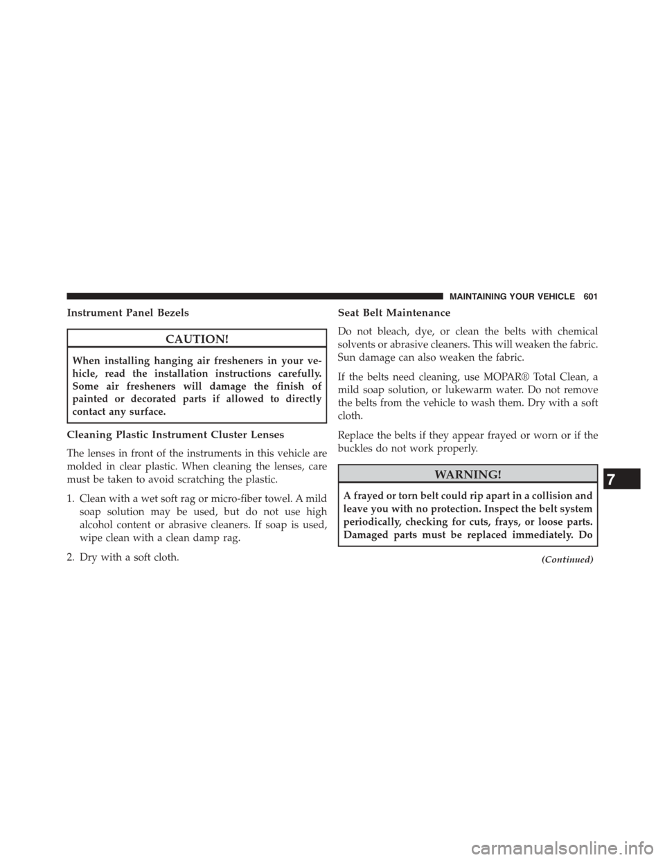
Instrument Panel Bezels
CAUTION!
When installing hanging air fresheners in your ve-
hicle, read the installation instructions carefully.
Some air fresheners will damage the finish of
painted or decorated parts if allowed to directly
contact any surface.
Cleaning Plastic Instrument Cluster Lenses
The lenses in front of the instruments in this vehicle are
molded in clear plastic. When cleaning the lenses, care
must be taken to avoid scratching the plastic.
1. Clean with a wet soft rag or micro-fiber towel. A mild
soap solution may be used, but do not use high
alcohol content or abrasive cleaners. If soap is used,
wipe clean with a clean damp rag.
2. Dry with a soft cloth.
Seat Belt Maintenance
Do not bleach, dye, or clean the belts with chemical
solvents or abrasive cleaners. This will weaken the fabric.
Sun damage can also weaken the fabric.
If the belts need cleaning, use MOPAR® Total Clean, a
mild soap solution, or lukewarm water. Do not remove
the belts from the vehicle to wash them. Dry with a soft
cloth.
Replace the belts if they appear frayed or worn or if the
buckles do not work properly.
WARNING!
A frayed or torn belt could rip apart in a collision and
leave you with no protection. Inspect the belt system
periodically, checking for cuts, frays, or loose parts.
Damaged parts must be replaced immediately. Do
(Continued)
7
MAINTAINING YOUR VEHICLE 601
Page 605 of 664
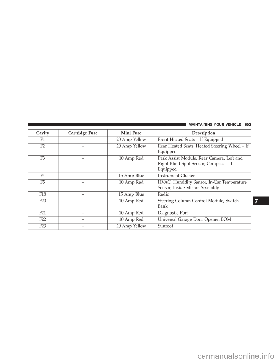
Cavity Cartridge FuseMini FuseDescription
F1–20 Amp Yellow Front Heated Seats – If Equipped
F2–20 Amp Yellow Rear Heated Seats, Heated Steering Wheel – If
Equipped
F3–10 Amp Red Park Assist Module, Rear Camera, Left and
Right Blind Spot Sensor, Compass – If
Equipped
F4–15 Amp Blue Instrument Cluster
F5–10 Amp Red HVAC, Humidity Sensor, In-Car Temperature
Sensor, Inside Mirror Assembly
F18–15 Amp Blue Radio
F20–10 Amp Red Steering Column Control Module, Switch
Bank
F21–10 Amp Red Diagnostic Port
F22–10 Amp Red Universal Garage Door Opener, EOM
F23–20 Amp Yellow Sunroof
7
MAINTAINING YOUR VEHICLE 603
Page 609 of 664
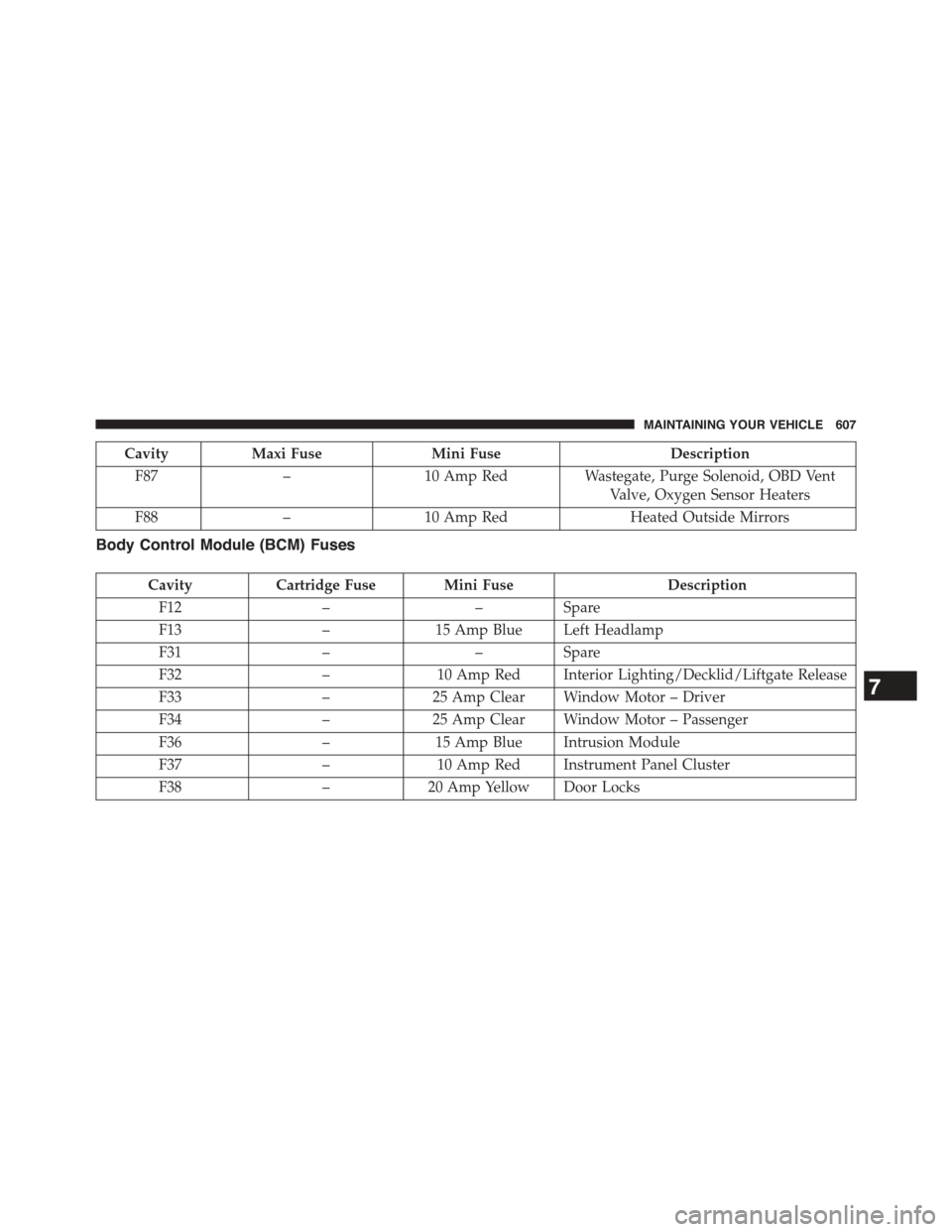
CavityMaxi FuseMini FuseDescription
F87–10 Amp RedWastegate, Purge Solenoid, OBD Vent
Valve, Oxygen Sensor Heaters
F88–10 Amp RedHeated Outside Mirrors
Body Control Module (BCM) Fuses
CavityCartridge Fuse Mini FuseDescription
F12––Spare
F13–15 Amp Blue Left Headlamp
F31––Spare
F32–10 Amp Red Interior Lighting/Decklid/Liftgate Release
F33–25 Amp Clear Window Motor – Driver
F34–25 Amp Clear Window Motor – Passenger
F36–15 Amp Blue Intrusion Module
F37–10 Amp Red Instrument Panel Cluster
F38–20 Amp Yellow Door Locks
7
MAINTAINING YOUR VEHICLE 607
Page 650 of 664
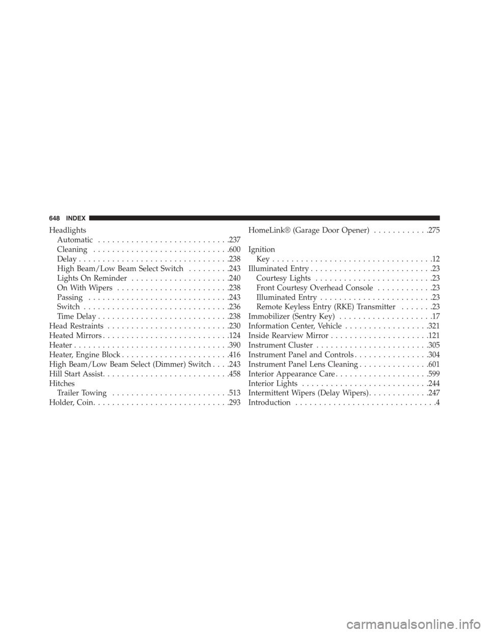
Headlights
Automatic............................237
Cleaning.............................600
Delay................................238
High Beam/Low Beam Select Switch.........243
Lights On Reminder.....................240
On With Wipers........................238
Passing..............................243
Switch...............................236
Time Delay............................238
Head Restraints..........................230
Heated Mirrors...........................124
Heater.................................390
Heater, Engine Block.......................416
High Beam/Low Beam Select (Dimmer) Switch . . . .243
Hill Start Assist...........................458
Hitches
Trailer Towing.........................513
Holder, Coin.............................293
HomeLink® (Garage Door Opener)............275
Ignition
Key . . . . . . . . . . . . . . . . . . . . . . . . . . . . . . . . . .12
Illuminated Entry..........................23
Courtesy Lights.........................23
Front Courtesy Overhead Console............23
Illuminated Entry........................23
Remote Keyless Entry (RKE) Transmitter.......23
Immobilizer (Sentry Key)....................17
Information Center, Vehicle..................321
Inside Rearview Mirror.....................121
Instrument Cluster........................305
Instrument Panel and Controls................304
Instrument Panel Lens Cleaning...............601
Interior Appearance Care....................599
Interior Lights...........................244
Intermittent Wipers (Delay Wipers).............247
Introduction..............................4
648 INDEX
Page 652 of 664
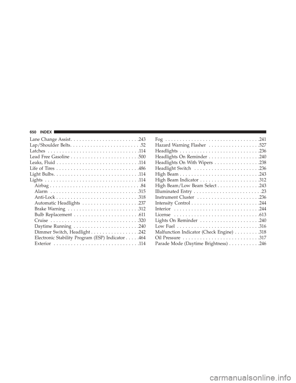
Lane Change Assist........................243
Lap/Shoulder Belts.........................52
Latches................................114
Lead Free Gasoline........................500
Leaks, Fluid.............................114
Life of Tires.............................486
Light Bulbs..............................114
Lights.................................114
Airbag................................84
Alarm...............................315
Anti-Lock.............................318
Automatic Headlights....................237
Brake Warning.........................312
Bulb Replacement.......................611
Cruise...............................320
Daytime Running.......................240
Dimmer Switch, Headlight.................242
Electronic Stability Program (ESP) Indicator.....464
Exterior..............................114
Fog . . . . . . . . . . . . . . . . . . . . . . . . . . . . . . . ..241
Hazard Warning Flasher..................527
Headlights............................236
Headlights On Reminder..................240
Headlights On With Wipers................238
Headlight Switch.......................236
High Beam............................243
High Beam Indicator.....................312
High Beam/Low Beam Select...............243
Illuminated Entry........................23
Instrument Cluster......................236
Intensity Control........................244
Interior..............................244
License..............................613
Lights On Reminder.....................240
Low Fuel.............................316
Malfunction Indicator (Check Engine).........318
Oil Pressure...........................317
Parade Mode (Daytime Brightness)...........246
650 INDEX