ignition DODGE DART 2015 PF / 1.G Workshop Manual
[x] Cancel search | Manufacturer: DODGE, Model Year: 2015, Model line: DART, Model: DODGE DART 2015 PF / 1.GPages: 664, PDF Size: 16.96 MB
Page 282 of 664
Canadian/Gate Operator Programming
For programming transmitters in Canada/United States
that require the transmitter signals to “time-out” after
several seconds of transmission.
Canadian radio frequency laws require transmitter sig-
nals to time-out (or quit) after several seconds of trans-
mission – which may not be long enough for HomeLink®
to pick up the signal during programming. Similar to this
Canadian law, some U.S. gate operators are designed to
time-out in the same manner.
It may be helpful to unplug the device during the cycling
process to prevent possible overheating of the garage
door or gate motor.
1. Cycle the ignition to the ON/RUN position.
2. Place the hand-held transmitter 1 to 3 inches (3 to 8
cm) away from the HomeLink® button you wish to
program while keeping the HomeLink® indicator
light in view.
3. Continue to push and hold the HomeLink® button,
while you press and release (“cycle”) your hand-held
transmitter every two seconds until HomeLink® has
successfully accepted the frequency signal. The indi-
cator light will flash slowly and then rapidly when
fully trained.
4. Watch for the HomeLink® indicator to change flash
rates. When it changes, it is programmed. It may take
up to 30 seconds or longer in rare cases. The garage
door may open and close while you are programming.
5. Push and hold the programmed HomeLink® button
and observe the indicator light.
280 UNDERSTANDING THE FEATURES OF YOUR VEHICLE
Page 283 of 664
NOTE:
•If the indicator light stays on constantly, program-
ming is complete and the garage door/device should
activate when the HomeLink® button is pushed.
•To program the two remaining HomeLink® buttons,
repeat each step for each remaining button. DO NOT
erase the channels.
If you unplugged the garage door opener/device for
programming, plug it back in at this time.
Reprogramming A Single HomeLink® Button
(Canadian/Gate Operator)
To reprogram a channel that has been previously trained,
follow these steps:
1. Cycle the ignition to the ON/RUN position.
2. Push and hold the desired HomeLink® button until
the indicator light begins to flash after 20 seconds.Do
not release the button.
3.Without releasing the buttonproceed with
“Canadian/Gate Operator Programming” step 2 and
follow all remaining steps.
Using HomeLink®
To operate, push and release the programmed
HomeLink® button. Activation will now occur for the
programmed device (i.e., garage door opener, gate opera-
tor, security system, entry door lock, home/office light-
ing, etc.,). The hand-held transmitter of the device may
also be used at any time.
Security
It is advised to erase all channels before you sell or turn
in your vehicle.
3
UNDERSTANDING THE FEATURES OF YOUR VEHICLE 281
Page 286 of 664
POWER SUNROOF — IF EQUIPPED
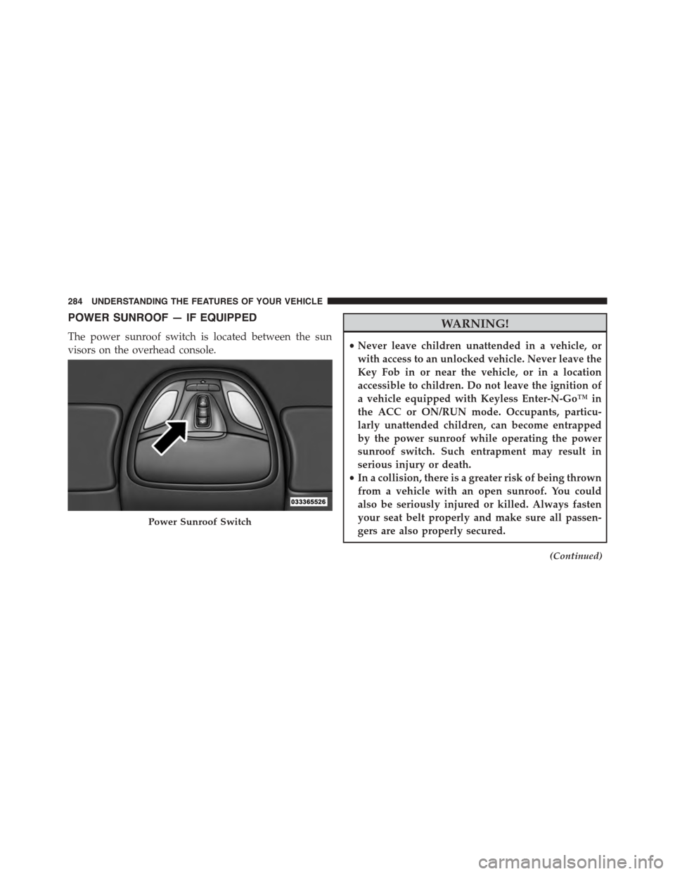
The power sunroof switch is located between the sun
visors on the overhead console.
WARNING!
•Never leave children unattended in a vehicle, or
with access to an unlocked vehicle. Never leave the
Key Fob in or near the vehicle, or in a location
accessible to children. Do not leave the ignition of
a vehicle equipped with Keyless Enter-N-Go™ in
the ACC or ON/RUN mode. Occupants, particu-
larly unattended children, can become entrapped
by the power sunroof while operating the power
sunroof switch. Such entrapment may result in
serious injury or death.
•In a collision, there is a greater risk of being thrown
from a vehicle with an open sunroof. You could
also be seriously injured or killed. Always fasten
your seat belt properly and make sure all passen-
gers are also properly secured.
(Continued)
Power Sunroof Switch
284 UNDERSTANDING THE FEATURES OF YOUR VEHICLE
Page 289 of 664
open or partially open positions. This is a normal occur-
rence and can be minimized. If the buffeting occurs with
the rear windows open, open the front and rear windows
together to minimize the buffeting. If the buffeting occurs
with the sunroof open, adjust the sunroof opening to
minimize the buffeting or open any window.
Sunroof Maintenance
Use only a nonabrasive cleaner and a soft cloth to clean
the glass panel.
ELECTRICAL POWER OUTLETS — IF EQUIPPED
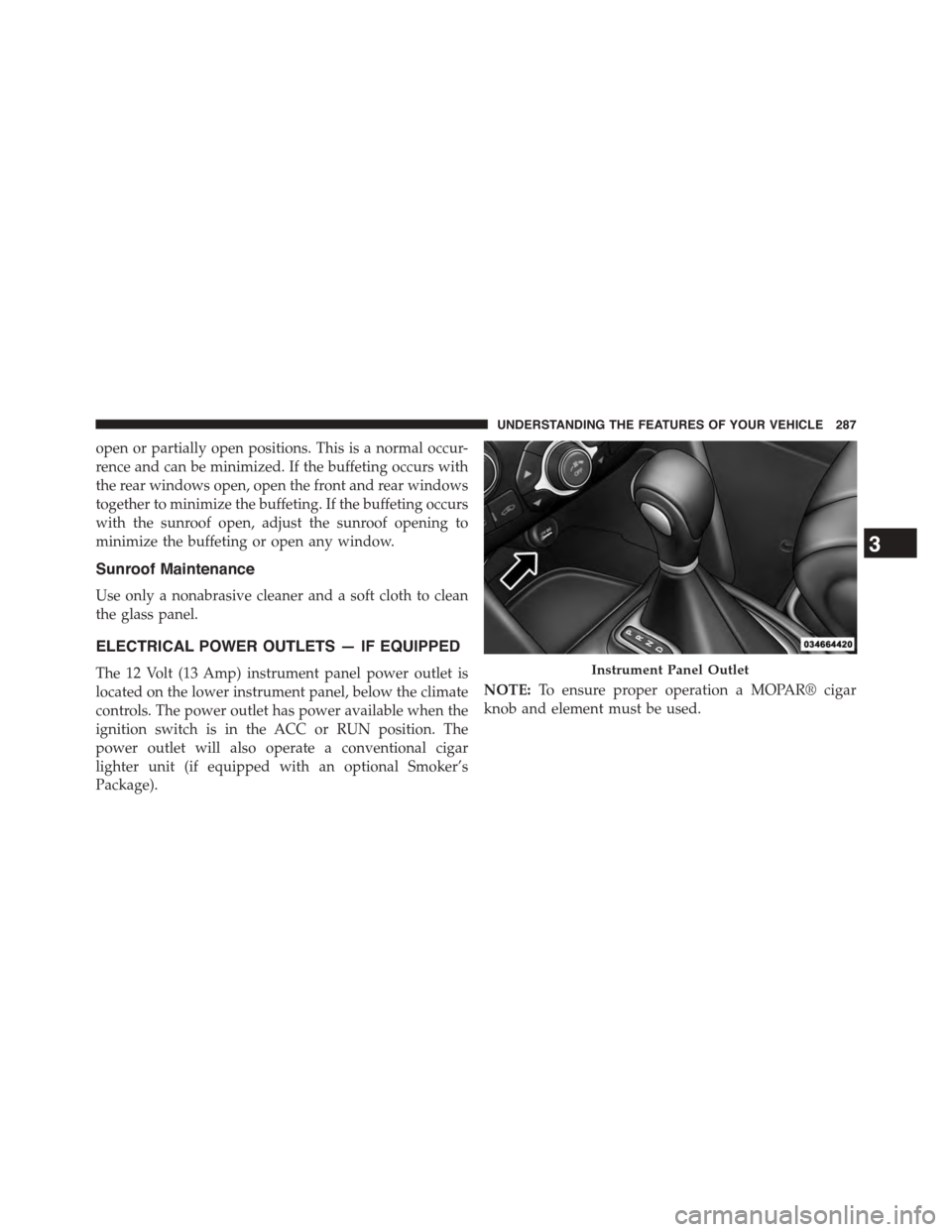
The 12 Volt (13 Amp) instrument panel power outlet is
located on the lower instrument panel, below the climate
controls. The power outlet has power available when the
ignition switch is in the ACC or RUN position. The
power outlet will also operate a conventional cigar
lighter unit (if equipped with an optional Smoker’s
Package).
NOTE:To ensure proper operation a MOPAR® cigar
knob and element must be used.
Instrument Panel Outlet
3
UNDERSTANDING THE FEATURES OF YOUR VEHICLE 287
Page 290 of 664
CAUTION!
•Do not exceed the maximum power of 160 Watts (13
Amps) at 12 Volts. If the 160 Watt (13 Amp) power
rating is exceeded the fuse protecting the system
will need to be replaced.
•Power outlets are designed for accessory plugs
only. Do not insert any other object in the power
outlets as this will damage the outlet and blow the
fuse. Improper use of the power outlet can cause
damage not covered by your New Vehicle Limited
Warranty.
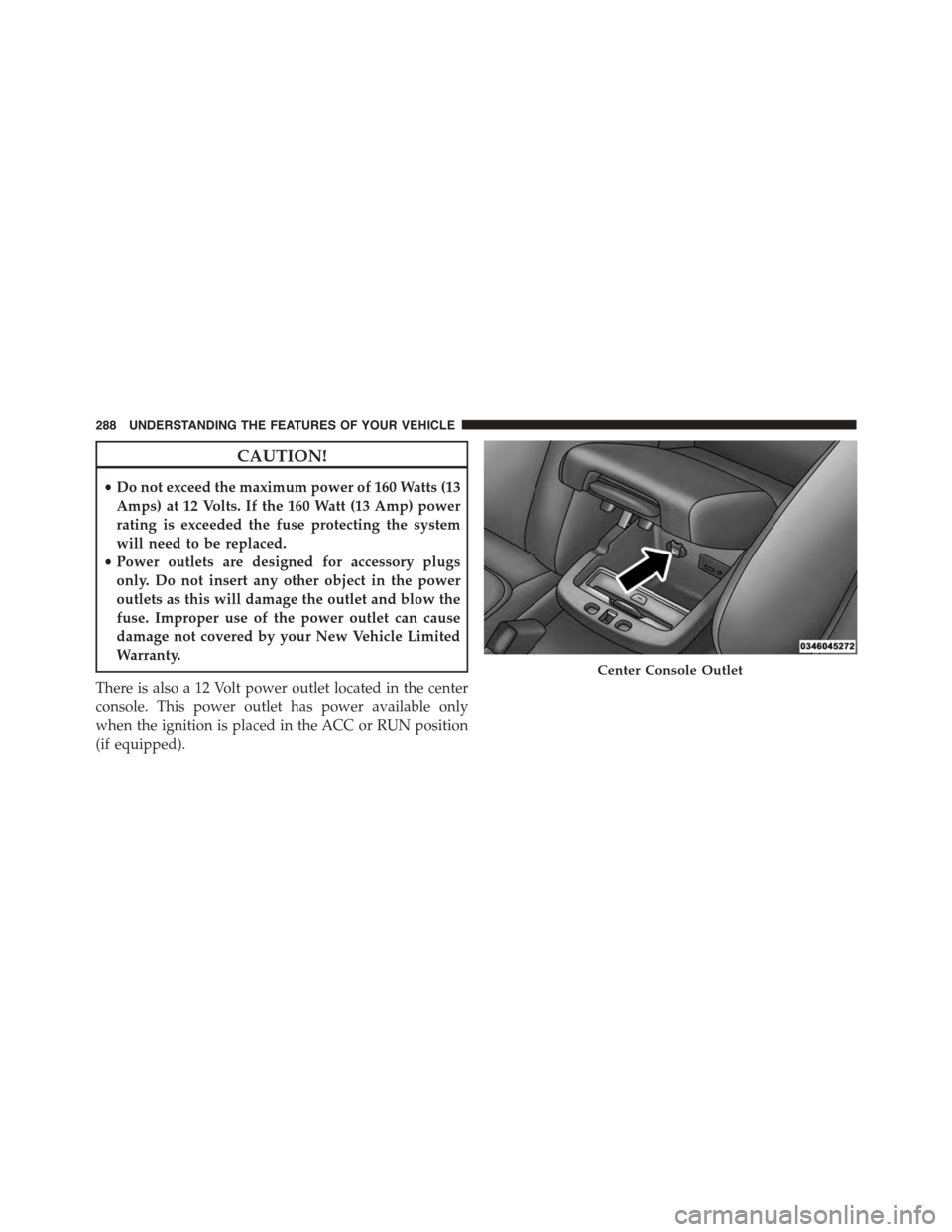
There is also a 12 Volt power outlet located in the center
console. This power outlet has power available only
when the ignition is placed in the ACC or RUN position
(if equipped).
Center Console Outlet
288 UNDERSTANDING THE FEATURES OF YOUR VEHICLE
Page 306 of 664
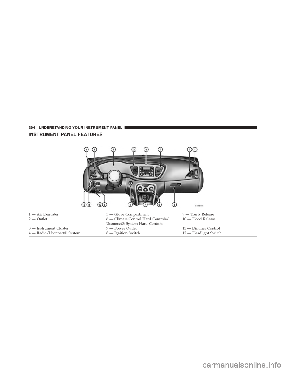
INSTRUMENT PANEL FEATURES
1—AirDemister5—GloveCompartment9—TrunkRelease2 — Outlet6 — Climate Control Hard Controls/Uconnect® System Hard Controls10 — Hood Release
3 — Instrument Cluster7 — Power Outlet11 — Dimmer Control4 — Radio/Uconnect® System8 — Ignition Switch12 — Headlight Switch
304 UNDERSTANDING YOUR INSTRUMENT PANEL
Page 312 of 664
4. Temperature Gauge
The temperature gauge shows engine coolant tempera-
ture. Any reading within the normal range indicates that
the engine cooling system is operating satisfactorily.
The gauge pointer will likely indicate a higher tempera-
ture when driving in hot weather, up mountain grades,
or when towing a trailer. It should not be allowed to
exceed the upper limits of the normal operating range.
CAUTION!
Driving with a hot engine cooling system could
damage your vehicle. If the temperature gauge reads
“H” pull over and stop the vehicle. Idle the vehicle
with the air conditioner turned off until the pointer
drops back into the normal range. If the pointer
remains on the “H” and you hear continuous chimes,
turn the engine off immediately and call an autho-
rized dealer for service.
WARNING!
A hot engine cooling system is dangerous. You or
others could be badly burned by steam or boiling
coolant. You may want to call an authorized dealer
for service if your vehicle overheats. If you decide to
look under the hood yourself, see “Maintaining Your
Vehicle”. Follow the warnings under the Cooling
System Pressure Cap paragraph.
5. Electronic Stability Control (ESC) Activation/
Malfunction Indicator Light — If Equipped
The “ESC Activation/Malfunction Indicator
Light” in the instrument cluster will come on
when the ignition switch is in the ON/RUN
position. It should go out with the engine
running. If the “ESC Activation/Malfunction Indicator
Light” comes on continuously with the engine running, a
malfunction has been detected in the ESC system. If this
310 UNDERSTANDING YOUR INSTRUMENT PANEL
Page 313 of 664
light remains on after several ignition cycles, and the
vehicle has been driven several miles (kilometers) at
speeds greater than 30 mph (48 km/h), see your autho-
rized dealer as soon as possible to have the problem
diagnosed and corrected.
NOTE:
•The “ESC Off Indicator Light” and the “ESC
Activation/Malfunction Indicator Light” come on
momentarily each time the ignition switch is placed
in the ON/RUN.
•Each time the ignition is turned to ON/RUN, the
ESC system will be ON, even if it was turned off
previously.
•The ESC system will make buzzing or clicking
sounds when it is active. This is normal; the sounds
will stop when ESC becomes inactive following the
maneuver that caused the ESC activation.
6. Front Fog Light Indicator — If Equipped
This indicator will illuminate when the front
fog lights are on.
7. Engine Temperature Warning Light
This light warns of an overheated engine condi-
tion. If the engine coolant temperature is too high,
this indicator will illuminate and a single chime will
sound.
If the light turns on while driving, safely pull over and
stop the vehicle. If the A/C system is on, turn it off. Also,
shift the transmission into NEUTRAL and idle the ve-
hicle. If the temperature reading does not return to
normal, turn the engine off immediately and call for
service. Refer to “If Your Engine Overheats” in “What To
Do In Emergencies” for further information.
4
UNDERSTANDING YOUR INSTRUMENT PANEL 311
Page 314 of 664
For vehicles equipped with a premium cluster this indi-
cator will display in the DID. Refer to ”Driver Informa-
tion Display (DID) — If Equipped” for further
information.
8. High Beam Indicator
This indicator shows that the high beam head-
lights are on. Push the multifunction lever for-
ward to switch the headlights to high beam, and pull
toward yourself (normal position) to return to low beam.
9. Seat Belt Reminder Light
When the ignition switch is placed in the ON/
RUN position, this light will turn on for four to
eight seconds as a bulb check. During the bulb
check, if the driver’s seat belt is unbuckled, a chime will
sound. After the bulb check or when driving, if the
driver’s seat belt remains unbuckled, the Seat Belt Re-
minder Light will illuminate and the chime will sound.
Refer to “Occupant Restraints” in “Things To Know
Before Starting Your Vehicle” for further information.
10. Brake Warning Light
This light monitors various brake functions,
including brake fluid level and parking brake
application. If the brake light turns on it may
indicate that the parking brake is applied, that
the brake fluid level is low, or that there is a problem with
the anti-lock brake system reservoir.
If the light remains on when the parking brake has been
disengaged, and the fluid level is at the full mark on the
master cylinder reservoir, it indicates a possible brake
hydraulic system malfunction or that a problem with the
Brake Booster has been detected by the Anti-Lock Brake
System (ABS)/Electronic Stability Control (ESC) system.
In this case, the light will remain on until the condition
has been corrected. If the problem is related to the brake
booster, the ABS pump will run when applying the brake
312 UNDERSTANDING YOUR INSTRUMENT PANEL
Page 315 of 664
and a brake pedal pulsation may be felt during each stop.
The dual brake system provides a reserve braking capac-
ity in the event of a failure to a portion of the hydraulic
system. A leak in either half of the dual brake system is
indicated by the Brake Warning Light, which will turn on
when the brake fluid level in the master cylinder has
dropped below a specified level.
The light will remain on until the cause is corrected.
NOTE:The light may flash momentarily during sharp
cornering maneuvers, which change fluid level condi-
tions. The vehicle should have service performed, and
the brake fluid level checked.
If brake failure is indicated, immediate repair is neces-
sary.
WARNING!
Driving a vehicle with the red brake light on is
dangerous. Part of the brake system may have failed.
It will take longer to stop the vehicle. You could have
a collision. Have the vehicle checked immediately.
Vehicles equipped with the Anti-Lock Brake System
(ABS), are also equipped with Electronic Brake Force
Distribution (EBD). In the event of an EBD failure, the
Brake Warning Light will turn on along with the ABS
Light. Immediate repair to the ABS system is required.
Operation of the Brake Warning Light can be checked by
turning the ignition switch from the OFF position to the
ON/RUN position. The light should illuminate for ap-
proximately two seconds. The light should then turn off
unless the parking brake is applied or a brake fault is
detected. If the light does not illuminate, have the light
inspected by an authorized dealer.
4
UNDERSTANDING YOUR INSTRUMENT PANEL 313