instrument cluster DODGE DART 2015 PF / 1.G Owner's Manual
[x] Cancel search | Manufacturer: DODGE, Model Year: 2015, Model line: DART, Model: DODGE DART 2015 PF / 1.GPages: 164, PDF Size: 25.19 MB
Page 94 of 164
Trip Info
Press the UPorDOWN button until the Trip Info icon is highlighted in the DID.
Press the RIGHTbutton to display the following three trip features in the next screen:
•TripA
•TripB
•ElapsedTime
Stored Message
Press the UPorDOWN button until the Messages display icon is highlighted in
the DID. This feature shows the number of stored warning messages. Pressing the RIGHT
button will allow you to see what the stored messages are. Press the LEFTbutton
to return to the Main Menu. The inner ring of the display will illuminate grey under normal
conditions, yellow for non critical warnings, red for critical warnings and white for on
demand information.
Screen Setup
•Screen Setup Display Analog Icon
•Screen Setup Display Digital Icon
Press the UPor DOWNbutton until the Screen Setup display icon is highlighted
in the DID. Press the RIGHTbutton to enter the Screen Setup submenu. The Screen
Setup feature allows you to change what information is displayed in the instrument cluster
as well as the location that information is displayed.
Press the UPor DOWNbutton until the Screen Setup display icon is highlighted
in the DID. Press the RIGHTbutton to enter the Screen Setup submenu. The Screen
Setup feature allows you to change the location that information is displayed within the
instrument cluster. Use the UP and DOWN buttons to highlight a screen setup location
(i.e., Upper Left, Upper Right, etc.) then press the RIGHT arrow button to select the
location and make changes. Press the UP and DOWN buttons to select the information
you would like to display in that location (i.e., Date, Time, Outside Temp, etc.) and press
the RIGHT arrow button to save the display setting. You can press the LEFT arrow button
at any time to back out of a submenu selection.
NOTE:
This option is only available when the vehicle is in the Park position.
ELECTRONICS
92
Page 102 of 164
ROADSIDE ASSISTANCE
Dial toll-free 1-800-521-2779 for U.S. Residents or 1-800-363-4869 for Canadian
Residents.
•Provideyourname,vehicleidentificationnumber,licenseplatenumber,andyour
location, including the telephone number from which you are calling.
•Brieflydescribethenatureoftheproblemandanswerafewsimplequestions.
•Youwillbegiventhenameoftheserviceproviderandanestimatedtimeofarrival.If
you feel you are in an “unsafe situation”, please let us know. With your consent, we will
contact local police or safety authorities.
INSTRUMENT CLUSTER WARNING LIGHTS
-ElectronicStabilityControl(ESC)Activation/MalfunctionIndicatorLight
The “ESC Activation/Malfunction Indicator Light” in the instrument cluster will come on
when the ignition switch is turned to the ON/RUN position. It should go out with the
engine running. If the “ESC Activation/Malfunction Indicator Light” comes on continu-
ously with the engine running, a malfunction has been detected in the ESC system.
If this light remains on after several ignition cycles, and the vehicle has been driven
several miles (kilometers) at speeds greater than 30 mph (48 km/h), we recommend you
drive to the nearest service center and have the vehicle serviced immediately.
-TirePressureMonitoringSystem(TPMS)Light
Each tire, including the spare (if provided), should be checked monthly when cold and
inflated to the inflation pressure recommended by the vehicle manufacturer on the
vehicle placard or tire inflation pressure label. (If your vehicle has tires of a different size
than the size indicated on the vehicle placard or tire inflation pressure label, you should
determine the proper tire inflation pressure for those tires.)
As an added safety feature, your vehicle has been equipped with a tire pressure
monitoring system (TPMS) that illuminates a low tire pressure telltale when one or more
of your tires is significantly under-inflated. Accordingly, when the low tire pressure telltale
illuminates, you should stop and check your tires as soon as possible, and inflate them to
the proper pressure. Driving on a significantly under-inflated tire causes the tire to
overheat and can lead to tire failure. Under-inflation also reduces fuel efficiency and tire
tread life, and may affect the vehicle’s handling and stopping ability.
IF THE LIGHT STARTS FLASHING INDICATING A LOW TIRE PRESSURE, ADJUST THE AIR
PRESSURE IN THE LOW TIRE TO THE AIR PRESSURE SHOWN ON THE VEHICLE PLACARD OR
TIRE INFLATION PRESSURE LABEL LOCATED ON THE DRIVER'S DOOR.
WHAT TO DO IN EMERGENCIES
100
Page 108 of 164
INSTRUMENT CLUSTER INDICATOR LIGHTS
-TurnSignalIndicator
The arrows will flash with the exterior turn signals when the turn signal lever is operated.
Atonewillchime,andaEVIC/DIDmessagewillappearifeitherturnsignalisleftonfor
more than 1 mile (1.6 km).
NOTE:
If either indicator flashes at a rapid rate, check for a defective outside light bulb.
-HighBeamIndicator
Indicates that headlights are on high beam.
-FrontFogLightIndicator
This indicator will illuminate when the front fog lights are on.
-VehicleSecurityLight
This light will flash rapidly for approximately 15 seconds when the vehicle security alarm
is arming. The light will flash at a slower speed continuously after the alarm is set. The
security light will also come on for about three seconds when the ignition is first turned on.
-ElectronicSpeedControlONIndicator
This indicator will illuminate when the electronic speed control has been activated to the
“ON” position.
-ElectronicSpeedControlSETIndicator
This indicator will illuminate when the cruising speed has been set.
-ElectronicStabilityControl(ESC)OFFIndicatorLight
This light indicates the Electronic Stability Control (ESC) is off.
-WindshieldWasherFluidLowIndicator
This indicator will illuminate when the windshield washer fluid is low.
WHAT TO DO IN EMERGENCIES
106
Page 136 of 164
MAINTENANCE SCHEDULE
Yo u r v e h i c l e i s e q u i p p e d w i t h a n a u t o m a t i c o i l c h a n g e i n d i c a t o r s y s t e m . T h e o i l c h a n g e
indicator system will remind you that it is time to take your vehicle in for scheduled
maintenance.
Based on engine operation conditions, the oil change indicator message will illuminate.
This means that service is required for your vehicle. Operating conditions such as frequent
short-trips, trailer tow, extremely hot or cold ambient temperatures, and E85 fuel usage
will influence when the “Change Oil” message is displayed. Severe Operating Conditions
can cause the change oil message to illuminate as early as 3,500 miles (5,600 km) since
last reset. Have your vehicle serviced as soon as possible, within the next 500 miles
(805 km).
Yo u r a u t h o r i z e d d e a l e r w i l l r e s e t t h e o i l c h a n g e i n d i c a t o r m e s s a g e a f t e r c o m p l e t i n g t h e
scheduled oil change. If a scheduled oil change is performed by someone other than your
authorized dealer, the message can be reset by referring to the steps described under
“Instrument Cluster Warning Lights” in “What To Do In Emergencies” in this guide or
“Electronic Vehicle Information Center (EVIC)/Driver Information Display (DID)” in “Un-
derstanding Your Instrument Panel” in your Owners Manual on the DVD for further
information.
NOTE:
Under no circumstances should oil change intervals exceed 10,000 miles
(16,000 km) or twelve months, whichever comes first.
Severe Duty All Models
Change Engine Oil at 4000 miles (6,500 km) if the vehicle is operated in a dusty and off
road environment. This type of vehicle use is considered Severe Duty.
• Once A Month Or Before A Long Trip:
•Checkengineoillevel.
•Checkwindshieldwasherfluidlevel.
•Checkthetireinflationpressuresandlookforunusualwearordamage.
•Checkthefluidlevelsofthecoolantreservoir,andbrakemastercylinderasneeded.
•Checkfunctionofallinteriorandexteriorlights.
MAINTAINING YOUR VEHICLE
134
Page 141 of 164
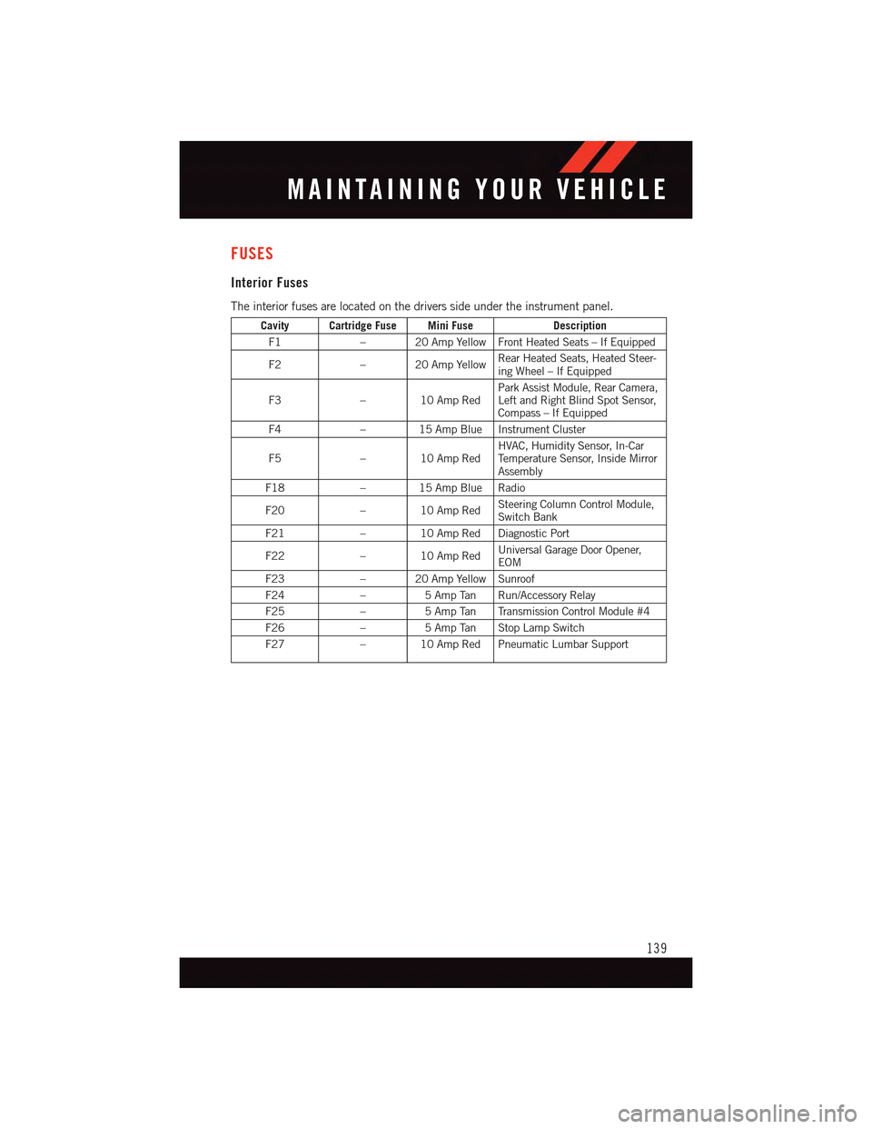
FUSES
Interior Fuses
The interior fuses are located on the drivers side under the instrument panel.
Cavity Cartridge Fuse Mini FuseDescription
F1–20AmpYellowFrontHeatedSeats–IfEquipped
F2–20AmpYellowRear Heated Seats, Heated Steer-ing Wheel – If Equipped
F3–10AmpRedPark Assist Module, Rear Camera,Left and Right Blind Spot Sensor,Compass – If Equipped
F4–15AmpBlueInstrumentCluster
F5–10AmpRedHVAC, Humidity Sensor, In-CarTe m p e r a t u r e S e n s o r, I n s i d e M i r r o rAssembly
F18–15AmpBlueRadio
F20–10AmpRedSteering Column Control Module,Switch Bank
F21–10AmpRedDiagnosticPort
F22–10AmpRedUniversal Garage Door Opener,EOM
F23–20AmpYellowSunroof
F24–5AmpTan Run/AccessoryRelay
F25–5AmpTan TransmissionControlModule#4
F26–5AmpTan StopLampSwitch
F27–10AmpRedPneumaticLumbarSupport
MAINTAINING YOUR VEHICLE
139
Page 143 of 164
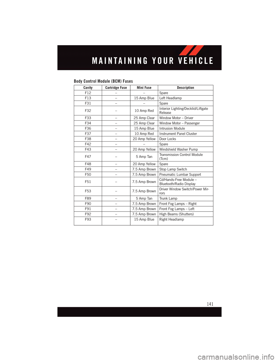
Body Control Module (BCM) Fuses
Cavity Cartridge Fuse Mini FuseDescription
F12––Spare
F13–15AmpBlueLeftHeadlamp
F31––Spare
F32–10AmpRedInterior Lighting/Decklid/LiftgateRelease
F33–25AmpClearWindowMotor–Driver
F34–25AmpClearWindowMotor–Passenger
F36–15AmpBlueIntrusionModule
F37–10AmpRedInstrumentPanelCluster
F38–20AmpYellowDoorLocks
F42––Spare
F43–20AmpYellowWindshieldWasherPump
F47–5AmpTanTr a n s m i s s i o n C o n t r o l M o d u l e(Tcm)
F48–20AmpYellowSpare
F49–7.5AmpBrownStopLampSwitch
F50–7.5AmpBrownPneumaticLumbarSupport
F51–7.5AmpBrownCd/Hands-Free Module –Bluetooth/Radio Display
F53–7.5AmpBrownDriver Window Switch/Power Mir-rors
F89–5AmpTan TrunkLamp
F90–7.5AmpBrownFrontFogLamps–Right
F91–7.5AmpBrownFrontFogLamps–Left
F92–7.5AmpBrownHighBeams(Shutters)
F93–15AmpBlueRightHeadlamp
MAINTAINING YOUR VEHICLE
141
Page 155 of 164
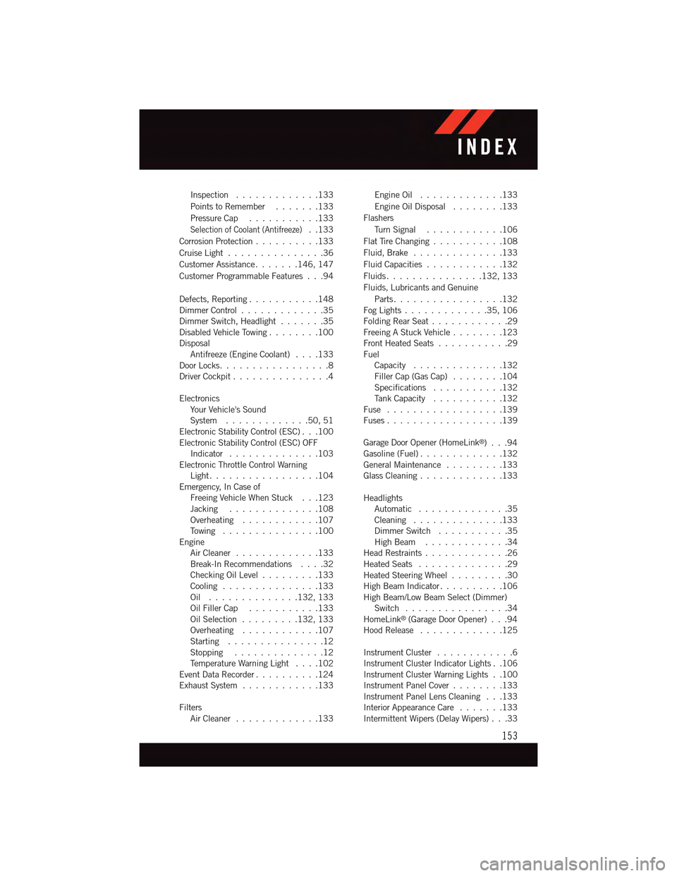
Inspection . . . . . . . . . . . . .133
Points to Remember.......133
Pressure Cap . . . . . . . . . . .133
Selection of Coolant (Antifreeze)..133
Corrosion Protection..........133
Cruise Light . . . . . . . . . . . . . . .36
Customer Assistance.......146, 147
Customer Programmable Features . . .94
Defects, Reporting...........148Dimmer Control.............35Dimmer Switch, Headlight.......35Disabled Vehicle Towing . . . . . . . .100DisposalAntifreeze (Engine Coolant)....133Door Locks.................8Driver Cockpit...............4
ElectronicsYo u r Ve h i c l e ' s S o u n dSystem.............50,51Electronic Stability Control (ESC) . . .100Electronic Stability Control (ESC) OFFIndicator . . . . . . . . . . . . . .103Electronic Throttle Control WarningLight . . . . . . . . . . . . . . . . .104Emergency, In Case ofFreeing Vehicle When Stuck . . .123Jacking . . . . . . . . . . . . . .108Overheating . . . . . . . . . . . .107To w i n g . . . . . . . . . . . . . . . 1 0 0EngineAir Cleaner.............133Break-In Recommendations....32Checking Oil Level.........133Cooling . . . . . . . . . . . . . . .133Oil . . . . . . . . . . . . . .132, 133Oil Filler Cap...........133Oil Selection . . . . . . . . .132, 133Overheating . . . . . . . . . . . .107Starting...............12Stopping..............12Te m p e r a t u r e W a r n i n g L i g h t....102Event Data Recorder..........124Exhaust System............133
FiltersAir Cleaner.............133
Engine Oil.............133
Engine Oil Disposal........133
Flashers
Tu r n S i g n a l............106
Flat Tire Changing...........108
Fluid, Brake . . . . . . . . . . . . . .133
Fluid Capacities............132
Fluids . . . . . . . . . . . . . . .132, 133
Fluids, Lubricants and Genuine
Parts . . . . . . . . . . . . . . . . .132Fog Lights . . . . . . . . . . . . .35, 106Folding Rear Seat............29Freeing A Stuck Vehicle . . . . . . . .123Front Heated Seats...........29FuelCapacity..............132Filler Cap (Gas Cap)........104Specifications...........132Ta n k C a p a c i t y...........132Fuse . . . . . . . . . . . . . . . . . .139Fuses . . . . . . . . . . . . . . . . . .139
Garage Door Opener (HomeLink®)...94Gasoline (Fuel).............132General Maintenance.........133Glass Cleaning.............133
HeadlightsAutomatic . . . . . . . . . . . . . .35Cleaning..............133Dimmer Switch...........35High Beam.............34Head Restraints.............26Heated Seats..............29Heated Steering Wheel.........30High Beam Indicator..........106High Beam/Low Beam Select (Dimmer)Switch . . . . . . . . . . . . . . . .34HomeLink®(Garage Door Opener) . . .94Hood Release.............125
Instrument Cluster............6Instrument Cluster Indicator Lights . .106Instrument Cluster Warning Lights . .100Instrument Panel Cover........133Instrument Panel Lens Cleaning . . .133Interior Appearance Care.......133Intermittent Wipers (Delay Wipers) . . .33
INDEX
153