oil pressure DODGE DART 2015 PF / 1.G User Guide
[x] Cancel search | Manufacturer: DODGE, Model Year: 2015, Model line: DART, Model: DODGE DART 2015 PF / 1.GPages: 164, PDF Size: 25.19 MB
Page 91 of 164
•Pushthebuttoninthecentertoselectthenextpresetstation(radio)ortochangeCDs
if equipped with a CD Changer.
ELECTRONIC VEHICLE INFORMATION CENTER (EVIC) —
STANDARD (2 BUTTON)
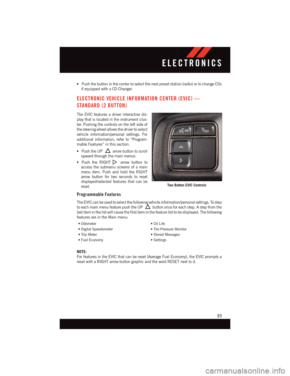
The EVIC features a driver interactive dis-
play that is located in the instrument clus-
ter. Pushing the controls on the left side of
the steering wheel allows the driver to select
vehicle information/personal settings. For
additional information, refer to “Program-
mable Features” in this section.
•PushtheUParrow button to scroll
upward through the main menus.
•PushtheRIGHTarrow button to
access the submenu screens of a main
menu item. Push and hold the RIGHT
arrow button for two seconds to reset
displayed/selected features that can be
reset.
Programmable Features
The EVIC can be used to select the following vehicle information/personal settings. To step
to each main menu feature push the UPbutton once for each step. A step from the
last item in the list will cause the first item in the feature list to be displayed. The following
features are in the Main menu:
•Odometer•OilLife
•DigitalSpeedometer•TirePressureMonitor
•TripMeter•StoredMessages
•FuelEconomy•Settings
NOTE:
For features in the EVIC that can be reset (Average Fuel Economy), the EVIC prompts a
reset with a RIGHT arrow button graphic and the word RESET next to it.
Two Button EVIC Controls
ELECTRONICS
89
Page 93 of 164
DID Selectable Menu Items
The following items can be selected in the DID menu.
Full Speedometer Analog Or Digital Display
•Full Speedometer Analog Display Icon.
•Full Speedometer Digital Display Icon.
Press the UPorDOWN button until the Analog or Digital display icon is
highlighted in the DID. Press the RIGHTbutton to change the display between analog
and digital.
Vehicle Speed MPH/km/h
Press the UPorDOWN button until the Vehicle Speed icon is highlighted in the
DID. Press the RIGHTbutton to view a digital display of the current speed in MPH or
km/h. Pressing the RIGHTbutton a second time will toggle the unit of measure
between mph or km/h. Press the LEFTbutton to return to the main menu.
Vehicle Info (Customer Information Features)
Press the UPor DOWNbutton until the Vehicle Info icon is highlighted in the
DID. Press the RIGHTbutton and Coolant Temp will be displayed. Press the UP or
DOWN arrow button to scroll through the following information submenus:
•TirePressure
•CoolantTemperature
•OilTemperature
•OilLife
Fuel Economy
Press the UPorDOWN button until the Fuel Economy icon is highlighted. Press
the RIGHTbutton and the next screen will display the following:
•AverageFuelEconomy/MilesPerGallon(MPGBargraph)
•DistanceToEmpty(DTE)
•CurrentMilesPerGallon(MPG)
Navigation
Press the UPor DOWNbutton until the Navigation icon is highlighted in the
DID. Press the RIGHTbutton to display the Navigation screen in the center of the DID
display.
ELECTRONICS
91
Page 105 of 164
The light also will turn on when the parking brake is applied with the ignition switch in the
ON/RUN position.
NOTE:
This light shows only that the parking brake is applied. It does not show the degree of
brake application.
WARNING!
Driving a vehicle with the red brake light on is dangerous. Part of the brake system may
have failed. It will take longer to stop the vehicle. You could have a collision. Have the
vehicle checked immediately.
-MalfunctionIndicatorLight(MIL)
Certain conditions, such as a loose or missing gas cap, poor fuel quality, etc., may
illuminate the MIL after engine start. The vehicle should be serviced if the light stays on
through several typical driving cycles. In most situations, the vehicle will drive normally
and not require towing.
If the MIL flashes when the engine is running, serious conditions may exist that could lead
to immediate loss of power or severe catalytic converter damage. We recommend you do
not operate the vehicle. Have the vehicle serviced immediately.
-ElectronicStabilityControl(ESC)OFFIndicatorLight
This light indicates the Electronic Stability Control (ESC) is off.
-ChargingSystemLight
This light shows the status of the electrical charging system. If the charging system light
remains on, it means that the vehicle is experiencing a problem with the charging system.
We recommend you do not continue driving if the charging system light is on. Have the
vehicle serviced immediately.
-OilPressureWarningLight
This light indicates low engine oil pressure. If the light turns on while driving, stop the
vehicle and shut off the engine as soon as possible. A chime will sound when this light
turns on.
We recommend you do not operate the vehicle or engine damage will occur. Have the
vehicle serviced immediately.
-Anti-LockBrake(ABS)Light
This light monitors the Anti-Lock Brake System (ABS).
If the light is not on during starting, stays on, or turns on while driving, we recommend you
contact the nearest authorized dealer and have the vehicle serviced immediately.
WHAT TO DO IN EMERGENCIES
103
Page 119 of 164
If the tire does not inflate to at least 26 psi (1.8 Bar) pressure within 15 minutes:
The tire is too badly damaged. Do not attempt to drive the vehicle further. Call for
assistance.
NOTE:
If the tire becomes over-inflated, press the Deflation Button to reduce the tire pressure to
the recommended inflation pressure before continuing.
If the tire inflates to the recommended pressure or is at least 26 psi (1.8 Bar) pressure
within 15 minutes:
1. Press the Power Button (4) to turn off the Tire Service Kit.
2. Remove the Speed Limit sticker from the top of the Sealant Bottle (1) and place the
sticker on the instrument panel.
3. Immediately disconnect the Sealant Hose (6) from the valve stem, reinstall the cap on
the fitting at the end of the hose, and place the Tire Service Kit in the vehicle storage
location. Quickly proceed to (D) “Drive Vehicle.”
(D) Drive Vehicle:
Immediately after injecting sealant and inflating the tire, drive the vehicle 5 miles (8 km)
or 10 minutes to ensure distribution of the Tire Service Kit Sealant within the tire. Do not
exceed 55 mph (88 km/h).
(E) After Driving:
Pull over to a safe location. Refer to “Whenever You Stop to Use Tire Service Kit” before
continuing.
1. Turn the Mode Select Knob (5) to the Air Mode position.
2. Uncoil the Air Pump Hose (7) (black in color) and screw the fitting at the end of
hose (7) onto the valve stem.
3. Uncoil the power plug and insert the plug into the vehicles 12 Volt power outlet.
4. Check the pressure in the tire by reading the Pressure Gauge (3).
WHAT TO DO IN EMERGENCIES
117
Page 120 of 164
If tire pressure is less than 19 psi (1.3 Bar), the tire is too badly damaged. Do not attempt
to drive the vehicle further. Call for assistance.
If the tire pressure is 19 psi (1.3 Bar) or higher:
1. Press the Power Button (4) to turn on Tire Service Kit and inflate the tire to the pressure
indicated on the tire and loading information label on the driver-side door opening.
2. Disconnect the Tire Service Kit from the valve stem, reinstall the cap on the valve stem
and unplug from 12 Volt outlet.
3. Place the Tire Service Kit in its proper storage area in the vehicle.
4. Have the tire inspected and repaired or replaced at the earliest opportunity at an
authorized dealer or tire service center.
5. Remove the Speed Limit sticker from the instrument panel after the tire has been
repaired.
6. Replace the Sealant Bottle (1) and Sealant Hose (6) assembly at your authorized
dealer as soon as possible. Refer to “(F) Sealant Bottle and Hose Replacement.”
NOTE:
•Ifthetirebecomesover-inflated,presstheDeflationButtontoreducethetirepressure
to the recommended inflation pressure before continuing.
•Whenhavingthetireserviced,advisetheauthorizeddealerorservicecenterthatthe
tire has been sealed using the Tire Service Kit.
(F) Sealant Bottle And Hose Replacement:
1. Uncoil the Sealant Hose (6) (clear in color).
2. Locate the round Sealant Bottle release button in the recessed area under the sealant
bottle.
3. Press the Sealant Bottle release button. The Sealant Bottle (1) will pop up. Remove
the bottle and dispose of it accordingly.
4. Clean any remaining sealant from the Tire Service Kit housing.
5. Position the new Sealant Bottle (1) in the housing so that the Sealant Hose (6) aligns
with the hose slot in the front of the housing. Press the bottle into the housing. An
audible click will be heard indicating the bottle is locked into place.
6. Verify that the cap is installed on the fitting at the end of the Sealant Hose (6) and
return the hose to its storage area (located on the bottom of the air pump).
7. Return the Tire Service Kit to its storage location in the vehicle.
WHAT TO DO IN EMERGENCIES
118
Page 136 of 164
MAINTENANCE SCHEDULE
Yo u r v e h i c l e i s e q u i p p e d w i t h a n a u t o m a t i c o i l c h a n g e i n d i c a t o r s y s t e m . T h e o i l c h a n g e
indicator system will remind you that it is time to take your vehicle in for scheduled
maintenance.
Based on engine operation conditions, the oil change indicator message will illuminate.
This means that service is required for your vehicle. Operating conditions such as frequent
short-trips, trailer tow, extremely hot or cold ambient temperatures, and E85 fuel usage
will influence when the “Change Oil” message is displayed. Severe Operating Conditions
can cause the change oil message to illuminate as early as 3,500 miles (5,600 km) since
last reset. Have your vehicle serviced as soon as possible, within the next 500 miles
(805 km).
Yo u r a u t h o r i z e d d e a l e r w i l l r e s e t t h e o i l c h a n g e i n d i c a t o r m e s s a g e a f t e r c o m p l e t i n g t h e
scheduled oil change. If a scheduled oil change is performed by someone other than your
authorized dealer, the message can be reset by referring to the steps described under
“Instrument Cluster Warning Lights” in “What To Do In Emergencies” in this guide or
“Electronic Vehicle Information Center (EVIC)/Driver Information Display (DID)” in “Un-
derstanding Your Instrument Panel” in your Owners Manual on the DVD for further
information.
NOTE:
Under no circumstances should oil change intervals exceed 10,000 miles
(16,000 km) or twelve months, whichever comes first.
Severe Duty All Models
Change Engine Oil at 4000 miles (6,500 km) if the vehicle is operated in a dusty and off
road environment. This type of vehicle use is considered Severe Duty.
• Once A Month Or Before A Long Trip:
•Checkengineoillevel.
•Checkwindshieldwasherfluidlevel.
•Checkthetireinflationpressuresandlookforunusualwearordamage.
•Checkthefluidlevelsofthecoolantreservoir,andbrakemastercylinderasneeded.
•Checkfunctionofallinteriorandexteriorlights.
MAINTAINING YOUR VEHICLE
134
Page 153 of 164
•HowdoIusetheUconnect®Voice Command?
•Uconnect®200 pg. 59
•Uconnect®8.4 & 8.4N pg. 86
•HowdoIoperatetheSteeringWheelAudioControls?pg.88
•HowdoIconfiguremyUniversalGarageDoorOpener(HomeLink)?pg.94
UTILITY
•HowdoIknowhowmuchIcantowwithmyDodgeDart?pg.98
WHAT TO DO IN EMERGENCIES
•WhatdoIdoifmyTPMSwarninglightcomeson?pg.100
•HowdoIchangeaflattire?pg.108
•HowdoIJump-Startmyvehicle?pg.120
MAINTAINING YOUR VEHICLE
•WhereismyFuseBlocklocated?pg.139
•WhattypeofoildoIuse?pg.132
•HowoftenshouldIchangemyengine’soil?pg.134
•Whatshouldmytirepressurebesetat?pg.142
FAQ
151
Page 154 of 164
Adding Engine Coolant (Antifreeze) . .133
Adding Washer Fluid..........133
Air Bag
Advanced Front Air Bag.......16
Advance Front Air Bag.......16
Air Bags . . . . . . . . . . . . . . .16
Air Bag Warning Light . . . . . . . .16
Front Air Bag . . . . . . . . . . . .16
Rollover . . . . . . . . . . . . . . .16
Side Impacts.............16
Air bag Light . . . . . . . . . . . . . .104Air Cleaner, Engine (Engine Air CleanerFilter)................133Air Conditioner Maintenance.....133Air Conditioning Refrigerant......133Air Conditioning System........133AlarmVehicle Security Alarm.......13Alarm (Security Alarm)......13,106Antifreeze (Engine Coolant) . . .132, 133Capacities.............132Disposal . . . . . . . . . . . . . .133Anti-Lock Warning Light........103Appearance Care............133Assistance Towing...........100Audio Settings............53,56Audio Systems (Radio)..........5Automatic Headlights..........35Automatic TemperatureControl (ATC) . . . . . . . . . . .39, 41Automatic TransmissionFluid Type . . . . . . . . . . . . .133
Back-Up Camera............44Battery.................133Blind Spot Monitoring..........44Body Mechanism Lubrication.....133Brake Fluid . . . . . . . . . . . . . . .133Brakes . . . . . . . . . . . . . . . . .133Brake System.............133Master Cylinder..........133Warning Light . . . . . . . . . . .102Break-In Recommendations, NewVehicle . . . . . . . . . . . . . . . .32Bulb Replacement...........145Bulbs, Light . . . . . . . . . . . . . .145
Calibration, Compass..........90
Capacities, Antifreeze (Engine
Coolant)...............132
Capacities, Fluid............132
Caps, Filler
Oil (Engine)............133
Car Washes . . . . . . . . . . . . . . .133
Change Oil Indicator..........104
Changing A Flat Tire..........108
Charging System Light.........103
Child Restraint..............22
Child RestraintsChild Tether AnchorageLocations...............25CleaningWheels...............133Windshield Wiper Blades.....133Climate Control . . . . . . . . . . . . . .5Clock Setting...............53Cluster Warning/Indicator LightsAnti-Lock Brake (ABS) Light . . .103Brake Warning Light . . . . . . . .102Charging System Light......103Electronic Speed Control ONIndicator . . . . . . . . . . . . . .106Electronic Speed Control SETIndicator . . . . . . . . . . . . . .106Electronic Throttle Control (ETC) Indi-cator Light . . . . . . . . . . . . .104Engine Temperature WarningLight . . . . . . . . . . . . . . . .102Front Fog Light Indicator . . . . .106High Beam Indicator.......106
Malfunction Indicator Light (MIL)..103Oil Pressure Warning Light . . . .103Ti r e P r e s s u r e M o n i t o r i n g S y s t e m(TPMS) Light...........100Tu r n S i g n a l I n d i c a t o r.......106Vehicle Security Light.......106Clutch . . . . . . . . . . . . . . . . .133Clutch Fluid . . . . . . . . . . . . . .133Compact Spare Tire..........143Compass Calibration...........90Coolant (Antifreeze)..........132Cooling System . . . . . . . . . . . . .133Adding Coolant (Antifreeze)....133Coolant Level...........133Disposal of Used Coolant.....133Drain, Flush, and Refill......133
INDEX
152
Page 155 of 164
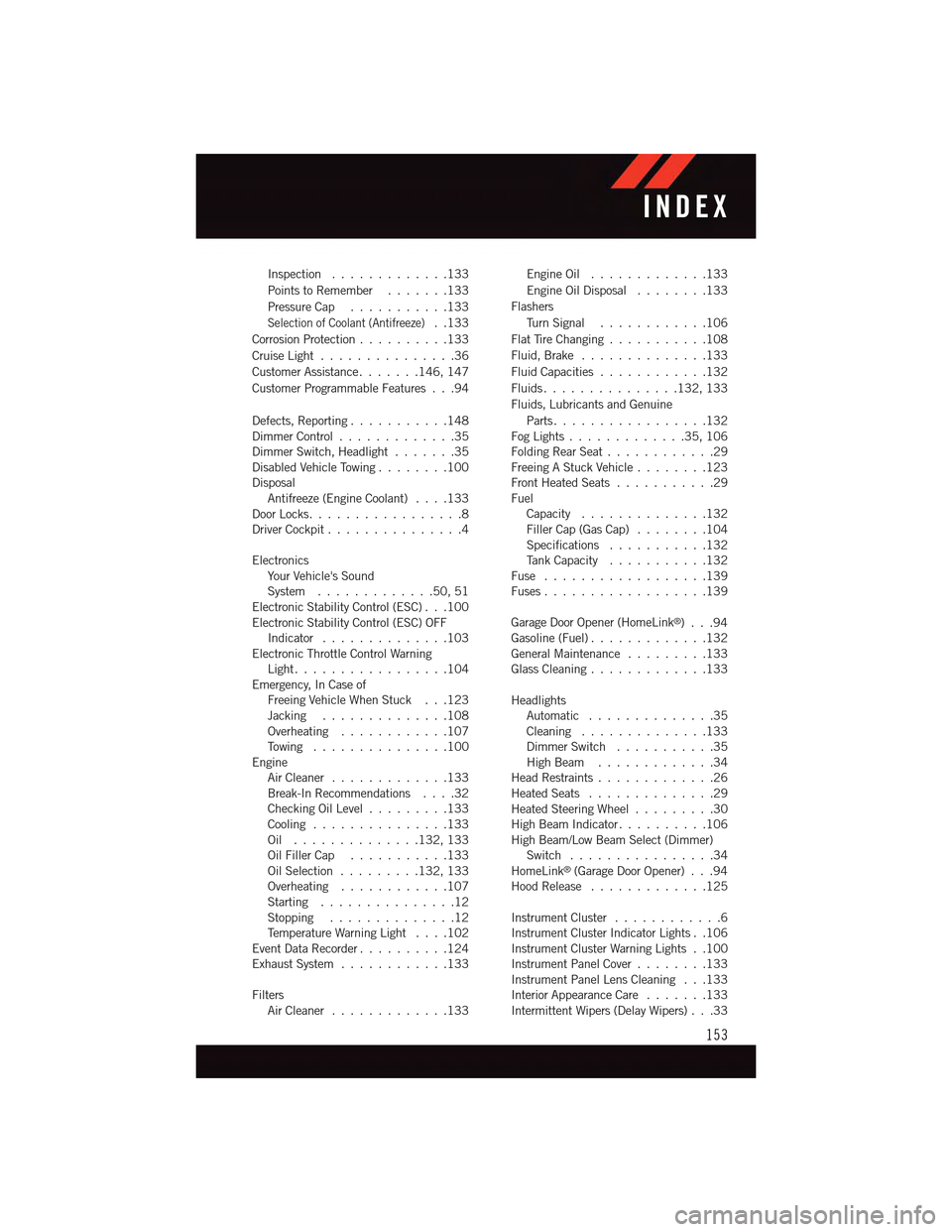
Inspection . . . . . . . . . . . . .133
Points to Remember.......133
Pressure Cap . . . . . . . . . . .133
Selection of Coolant (Antifreeze)..133
Corrosion Protection..........133
Cruise Light . . . . . . . . . . . . . . .36
Customer Assistance.......146, 147
Customer Programmable Features . . .94
Defects, Reporting...........148Dimmer Control.............35Dimmer Switch, Headlight.......35Disabled Vehicle Towing . . . . . . . .100DisposalAntifreeze (Engine Coolant)....133Door Locks.................8Driver Cockpit...............4
ElectronicsYo u r Ve h i c l e ' s S o u n dSystem.............50,51Electronic Stability Control (ESC) . . .100Electronic Stability Control (ESC) OFFIndicator . . . . . . . . . . . . . .103Electronic Throttle Control WarningLight . . . . . . . . . . . . . . . . .104Emergency, In Case ofFreeing Vehicle When Stuck . . .123Jacking . . . . . . . . . . . . . .108Overheating . . . . . . . . . . . .107To w i n g . . . . . . . . . . . . . . . 1 0 0EngineAir Cleaner.............133Break-In Recommendations....32Checking Oil Level.........133Cooling . . . . . . . . . . . . . . .133Oil . . . . . . . . . . . . . .132, 133Oil Filler Cap...........133Oil Selection . . . . . . . . .132, 133Overheating . . . . . . . . . . . .107Starting...............12Stopping..............12Te m p e r a t u r e W a r n i n g L i g h t....102Event Data Recorder..........124Exhaust System............133
FiltersAir Cleaner.............133
Engine Oil.............133
Engine Oil Disposal........133
Flashers
Tu r n S i g n a l............106
Flat Tire Changing...........108
Fluid, Brake . . . . . . . . . . . . . .133
Fluid Capacities............132
Fluids . . . . . . . . . . . . . . .132, 133
Fluids, Lubricants and Genuine
Parts . . . . . . . . . . . . . . . . .132Fog Lights . . . . . . . . . . . . .35, 106Folding Rear Seat............29Freeing A Stuck Vehicle . . . . . . . .123Front Heated Seats...........29FuelCapacity..............132Filler Cap (Gas Cap)........104Specifications...........132Ta n k C a p a c i t y...........132Fuse . . . . . . . . . . . . . . . . . .139Fuses . . . . . . . . . . . . . . . . . .139
Garage Door Opener (HomeLink®)...94Gasoline (Fuel).............132General Maintenance.........133Glass Cleaning.............133
HeadlightsAutomatic . . . . . . . . . . . . . .35Cleaning..............133Dimmer Switch...........35High Beam.............34Head Restraints.............26Heated Seats..............29Heated Steering Wheel.........30High Beam Indicator..........106High Beam/Low Beam Select (Dimmer)Switch . . . . . . . . . . . . . . . .34HomeLink®(Garage Door Opener) . . .94Hood Release.............125
Instrument Cluster............6Instrument Cluster Indicator Lights . .106Instrument Cluster Warning Lights . .100Instrument Panel Cover........133Instrument Panel Lens Cleaning . . .133Interior Appearance Care.......133Intermittent Wipers (Delay Wipers) . . .33
INDEX
153
Page 156 of 164
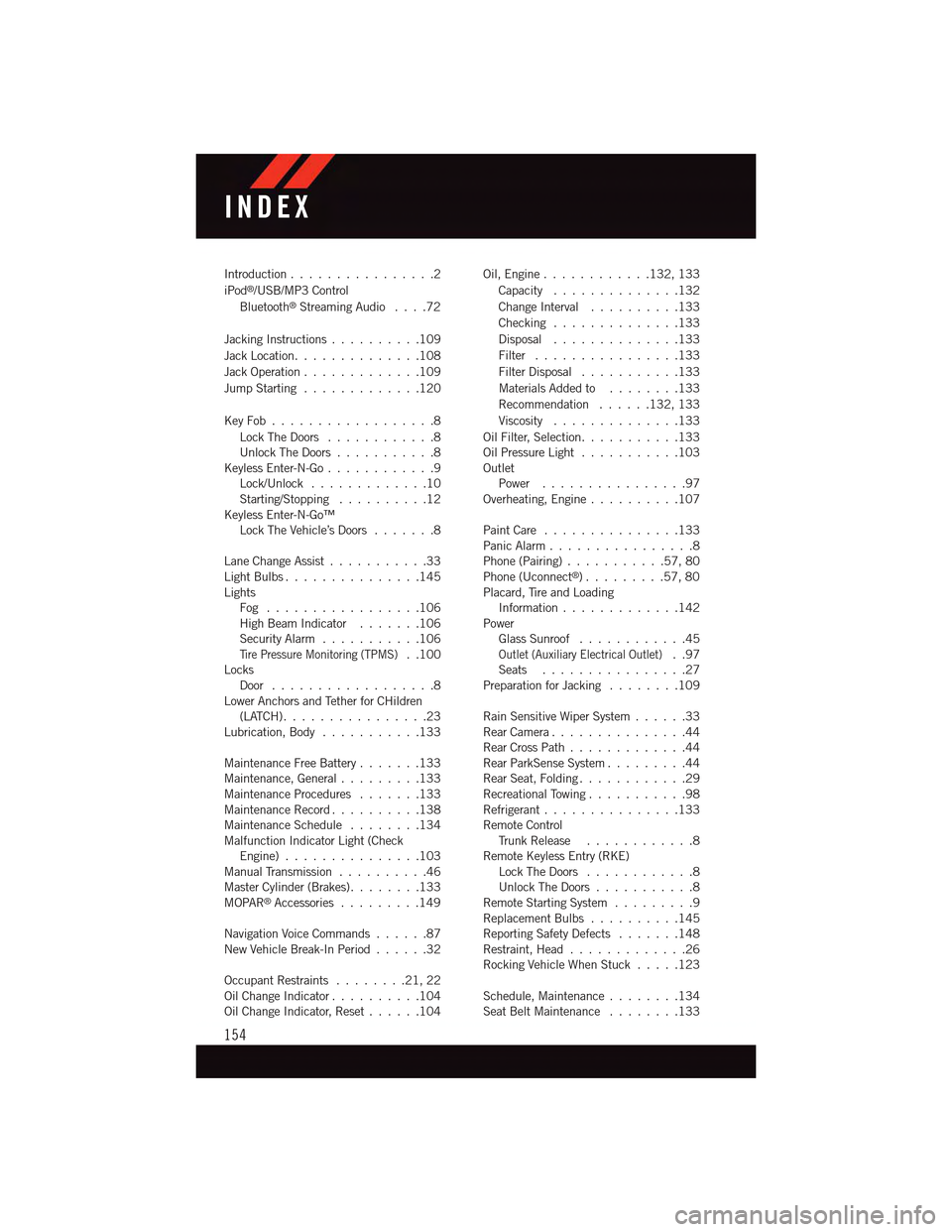
Introduction................2
iPod®/USB/MP3 Control
Bluetooth®Streaming Audio....72
Jacking Instructions . . . . . . . . . .109
Jack Location. . . . . . . . . . . . . .108
Jack Operation . . . . . . . . . . . . .109
Jump Starting.............120
Key Fob . . . . . . . . . . . . . . . . . .8
Lock The Doors............8Unlock The Doors...........8Keyless Enter-N-Go............9Lock/Unlock . . . . . . . . . . . . .10Starting/Stopping..........12Keyless Enter-N-Go™Lock The Vehicle’s Doors.......8
Lane Change Assist...........33Light Bulbs . . . . . . . . . . . . . . .145LightsFog . . . . . . . . . . . . . . . . .106High Beam Indicator . . . . . . .106Security Alarm...........106Ti r e P r e s s u r e M o n i t o r i n g ( T P M S )..100LocksDoor..................8Lower Anchors and Tether for CHildren(LATCH)................23Lubrication, Body...........133
Maintenance Free Battery . . . . . . .133Maintenance, General.........133Maintenance Procedures.......133Maintenance Record..........138Maintenance Schedule........134Malfunction Indicator Light (CheckEngine)...............103Manual Transmission..........46Master Cylinder (Brakes)........133MOPAR®Accessories.........149
Navigation Voice Commands......87New Vehicle Break-In Period . . . . . .32
Occupant Restraints........21,22Oil Change Indicator..........104Oil Change Indicator, Reset......104
Oil, Engine............132, 133
Capacity..............132
Change Interval..........133
Checking..............133
Disposal..............133
Filter................133
Filter Disposal...........133
Materials Added to........133
Recommendation......132, 133
Viscosity..............133
Oil Filter, Selection...........133Oil Pressure Light . . . . . . . . . . .103OutletPower................97Overheating, Engine..........107
Paint Care . . . . . . . . . . . . . . .133Panic Alarm................8Phone (Pairing)...........57,80Phone (Uconnect®). . . . . . . . .57,80Placard, Tire and LoadingInformation . . . . . . . . . . . . .142PowerGlass Sunroof............45Outlet (Auxiliary Electrical Outlet)..97Seats................27Preparation for Jacking........109
Rain Sensitive Wiper System......33Rear Camera...............44Rear Cross Path.............44Rear ParkSense System.........44Rear Seat, Folding............29Recreational Towing...........98Refrigerant . . . . . . . . . . . . . . .133Remote ControlTr u n k R e l e a s e . . . . . . . . . . . . 8Remote Keyless Entry (RKE)Lock The Doors............8Unlock The Doors...........8Remote Starting System.........9Replacement Bulbs..........145Reporting Safety Defects.......148Restraint, Head.............26Rocking Vehicle When Stuck.....123
Schedule, Maintenance........134Seat Belt Maintenance........133
INDEX
154