transmission oil DODGE DART 2015 PF / 1.G User Guide
[x] Cancel search | Manufacturer: DODGE, Model Year: 2015, Model line: DART, Model: DODGE DART 2015 PF / 1.GPages: 164, PDF Size: 25.19 MB
Page 34 of 164
ENGINE BREAK-IN RECOMMENDATIONS
Alongbreak-inperiodisnotrequiredfortheengineanddrivetrain(transmissionandaxle)
in your vehicle.
Drive moderately during the first 300 miles (500 km). After the initial 60 miles (100 km),
speeds up to 50 or 55 mph (80 or 90 km/h) are desirable.
While cruising, brief full-throttle acceleration within the limits of local traffic laws
contributes to a good break-in. Wide-open throttle acceleration in low gear can be
detrimental and should be avoided.
The engine oil installed in the engine at the factory is a high-quality energy conserving type
lubricant. Oil changes should be consistent with anticipated climate conditions under
which vehicle operations will occur. For the recommended viscosity and quality grades,
refer to “Maintaining Your Vehicle.”
NOTE:
Anewenginemayconsumesomeoilduringitsfirstfewthousandmiles(kilometers)of
operation. This should be considered a normal part of the break-in and not interpreted as
an indication of an engine problem or malfunction.
CAUTION!
Never use Non-Detergent Oil or Straight Mineral Oil in the engine or damage may
result.
OPERATING YOUR VEHICLE
32
Page 104 of 164
-EngineTemperatureWarningLight
This light warns of an overheated engine condition.
If the light turns on or flashes continuously while driving, safely pull over and stop the
vehicle. If the A/C system is on, turn it off. Also, shift the transmission into NEUTRAL and
idle the vehicle. If the temperature reading does not return to normal, turn the engine off
immediately.
We recommend that you do not operate the vehicle or engine damage will occur. Have the
vehicle serviced immediately.
WARNING!
Ahotenginecoolingsystemisdangerous.Youorotherscouldbebadlyburnedby
steam or boiling coolant.
-BrakeWarningLight
This light monitors various brake functions, including brake fluid level and parking brake
application. If the brake light turns on it may indicate that the parking brake is applied,
that the brake fluid level is low, or that there is a problem with the anti-lock brake system
reservoir.
If the light remains on when the parking brake has been disengaged, and the fluid level is
at the full mark on the master cylinder reservoir, it indicates a possible brake hydraulic
system malfunction or that a problem with the Brake Booster has been detected by the
Anti-Lock Brake System (ABS)/Electronic Stability Control (ESC) system. In this case, the
light will remain on until the condition has been corrected. If the problem is related to the
brake booster, the ABS pump will run when applying the brake and a brake pedal
pulsation may be felt during each stop.
The dual brake system provides a reserve braking capacity in the event of a failure to a
portion of the hydraulic system. A leak in either half of the dual brake system is indicated
by the Brake Warning Light, which will turn on when the brake fluid level in the master
cylinder has dropped below a specified level. The light will remain on until the cause is
corrected.
Vehicles equipped with the Anti-Lock Brake System (ABS), are also equipped with
Electronic Brake Force Distribution (EBD). In the event of an EBD failure, the Brake
Warning Light will turn on along with the ABS Light. Immediate repair to the ABS system
is required.
Operation of the Brake Warning Light can be checked by turning the ignition switch from
the OFF position to the ON/RUN position. The light should illuminate for approximately
two seconds. The light should then turn off unless the parking brake is applied or a brake
fault is detected. If the light does not illuminate, have the light inspected by an authorized
dealer.
WHAT TO DO IN EMERGENCIES
102
Page 117 of 164
Tire Service Kit Usage Precautions
•ReplacetheTireServiceKitSealantBottle(1)andSealantHose(6)priortothe
expiration date (printed on the bottle label) to assure optimum operation of the system.
Refer to “Sealing A Tire With Tire Service Kit” section (F) “Sealant Bottle and Hose
Replacement.”
•TheSealantBottle(1)andSealantHose(6)areaonetireapplicationuse.Aftereach
use, always replace these components immediately at an authorized dealer.
•WhentheTireServiceKitsealantisinaliquidform,cleanwater,andadampclothwill
remove the material from the vehicle or tire and wheel components. Once the sealant
dries, it can easily be peeled off and properly discarded.
•Foroptimumperformance,makesurethevalvestemonthewheelisfreeofdebris
before connecting the Tire Service Kit.
•Yo u c a n u s e t h e Ti r e S e r v i c e K i t a i r p u m p t o i n f l a t e b i c y c l e t i r e s . T h e k i t a l s o c o m e s w i t h t w oneedles, located in the Accessory Storage Compartment (on the bottom of the air pump) forinflating sport balls, rafts, or similar inflatable items. However, use only the Air Pump Hose(7) and make sure the Mode Select Knob (5) is in the Air Mode when inflating such itemsto avoid injecting sealant into them. The Tire Service Kit Sealant is only intended to sealpunctures less than 1/4 inch (6 mm) diameter in the tread of your vehicle.
•DonotliftorcarrytheTireServiceKitbythehoses.
Sealing A Tire With Tire Service Kit
(A) Whenever You Stop To Use Tire Service Kit:
1. Pull over to a safe location and turn on the vehicle’s Hazard Warning flashers.
2.Verify that the valve stem (on the wheel with the deflated tire) is in a position that is near
to the ground. This will allow the Tire Service Kit Hoses (6) and (7) to reach the valve stem
and keep the Tire Service Kit flat on the ground. This will provide the best positioning of the
kit when injecting the sealant into the deflated tire and running the air pump. Move the
vehicle as necessary to place the valve stem in this position before proceeding.
3. Place the transmission in PARK (auto transmission) or in Gear (manual transmission)
and cycle the ignition to the OFF position.
4. Set the parking brake.
(B) Setting Up To Use Tire Service Kit:
1. Turn the Mode Select Knob (5) to the Sealant Mode position.
2. Uncoil the Sealant Hose (6) and then remove the cap from the fitting at the end of the
hose.
3. Place the Tire Service Kit flat on the ground next to the deflated tire.
4. Remove the cap from the valve stem and then screw the fitting at the end of the
Sealant Hose (6) onto the valve stem.
5. Uncoil the Power Plug (8) and insert the plug into the vehicle’s 12 Volt power outlet.
6. Do not remove foreign objects (e.g., screws or nails) from the tire.
WHAT TO DO IN EMERGENCIES
115
Page 135 of 164
CAUTION!
•Mixingofenginecoolant(antifreeze)otherthanspecifiedOrganicAdditiveTech-
nology (OAT) engine coolant (antifreeze), may result in engine damage and may
decrease corrosion protection. Organic Additive Technology (OAT) engine coolant is
different and should not be mixed with Hybrid Organic Additive Technology (HOAT)
engine coolant (antifreeze) or any “globally compatible” coolant (antifreeze). If a
non-OAT engine coolant (antifreeze) is introduced into the cooling system in an
emergency, the cooling system will need to be drained, flushed, and refilled with
fresh OAT coolant (conforming to MS-12106), by an authorized dealer as soon as
possible.
•Donotusewateraloneoralcohol-basedenginecoolant(antifreeze)products.Do
not use additional rust inhibitors or antirust products, as they may not be compat-
ible with the radiator engine coolant and may plug the radiator.
•Thisvehiclehasnotbeendesignedforusewithpropyleneglycol-basedengine
coolant (antifreeze). Use of propylene glycol-based engine coolant (antifreeze) is
not recommended.
Chassis
ComponentFluid, Lubricant, or Genuine Part
Automatic Transmission(1.4L Turbo Engine) – IfEquipped
Gear Oil:UseonlyMOPAR®CSeriesManual&DualDryClutch Transmission Fluid or equivalent.Control system:UseonlyMOPAR®CSeriesDDCTSAE75W Hydraulic Fluid or equivalent.Failure to use the correct fluid may affect the function orperformance of your transmission.
Automatic Transmission(2.0L And 2.4L Engine) – IfEquipped
Use only MOPAR®SP-IV Automatic Transmission Fluid orequivalent. Failure to use the correct fluid may affect thefunction or performance of your transmission
Manual Transmission – IfEquippedWe recommend you use MOPAR®CSeriesManual&DualDry Clutch Transmission Fluid.
Brake Master Cylinder We recommend you use MOPAR®DOT 3, SAE J1703. IfDOT 3, SAE J1703 brake fluid is not available, then DOT 4is acceptable.
MAINTENANCE PROCEDURES
For information on the maintenance procedures for your vehicle, please refer to “Main-
tenance Procedures” in “Maintaining Your Vehicle” in your Owner’s Manual or applicable
supplement on the DVD for further details.
MAINTAINING YOUR VEHICLE
133
Page 142 of 164
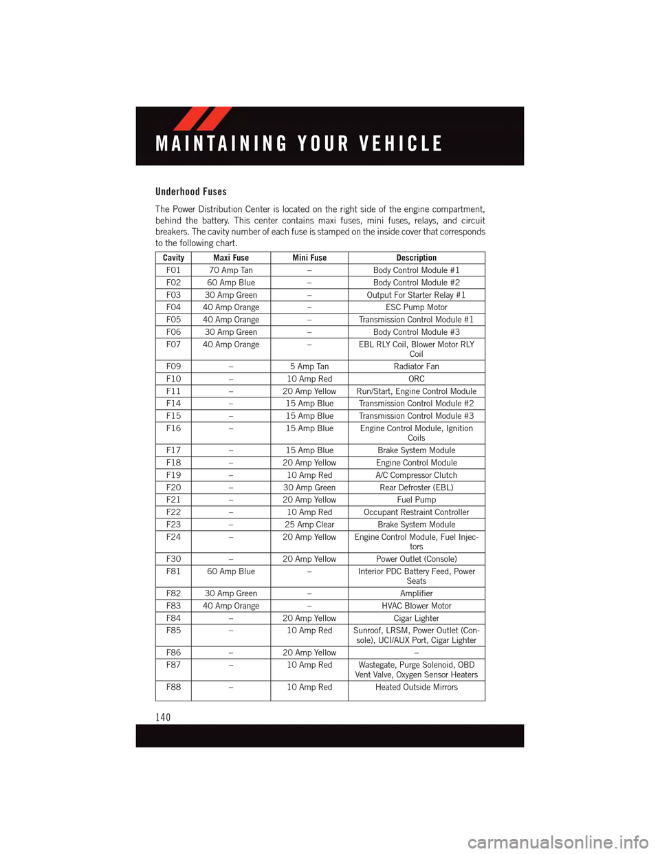
Underhood Fuses
The Power Distribution Center is located on the right side of the engine compartment,
behind the battery. This center contains maxi fuses, mini fuses, relays, and circuit
breakers. The cavity number of each fuse is stamped on the inside cover that corresponds
to the following chart.
Cavity Maxi FuseMini FuseDescription
F01 70 Amp Tan–Body Control Module #1
F02 60 Amp Blue–Body Control Module #2
F03 30 Amp Green–Output For Starter Relay #1
F04 40 Amp Orange–ESC Pump Motor
F05 40 Amp Orange–Tr a n s m i s s i o n C o n t r o l M o d u l e # 1
F06 30 Amp Green–Body Control Module #3
F07 40 Amp Orange–EBL RLY Coil, Blower Motor RLYCoil
F09–5AmpTanRadiator Fan
F10–10 Amp RedORC
F11–20 Amp Yellow Run/Start, Engine Control Module
F14–15 Amp Blue Transmission Control Module #2
F15–15 Amp Blue Transmission Control Module #3
F16–15 Amp Blue Engine Control Module, IgnitionCoils
F17–15 Amp BlueBrake System Module
F18–20 Amp Yellow Engine Control Module
F19–10 Amp RedA/C Compressor Clutch
F20–30 Amp GreenRear Defroster (EBL)
F21–20 Amp YellowFuel Pump
F22–10 Amp Red Occupant Restraint Controller
F23–25 Amp ClearBrake System Module
F24–20 Amp Yellow Engine Control Module, Fuel Injec-tors
F30–20 Amp Yellow Power Outlet (Console)
F81 60 Amp Blue–Interior PDC Battery Feed, PowerSeats
F82 30 Amp Green–Amplifier
F83 40 Amp Orange–HVAC Blower Motor
F84–20 Amp YellowCigar Lighter
F85–10 Amp Red Sunroof, LRSM, Power Outlet (Con-sole), UCI/AUX Port, Cigar Lighter
F86–20 Amp Yellow–
F87–10 Amp Red Wastegate, Purge Solenoid, OBDVent Valve, Oxygen Sensor Heaters
F88–10 Amp Red Heated Outside Mirrors
MAINTAINING YOUR VEHICLE
140
Page 154 of 164
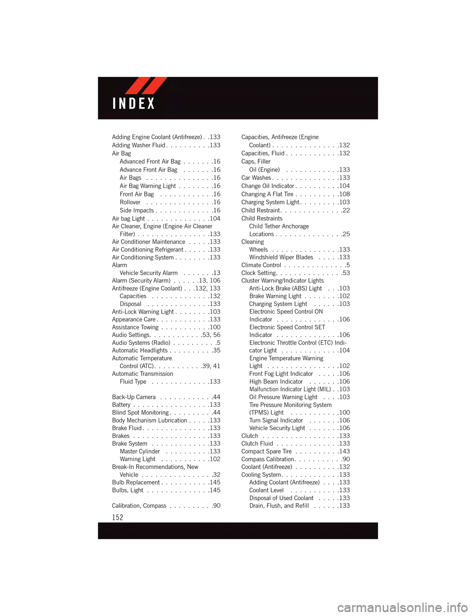
Adding Engine Coolant (Antifreeze) . .133
Adding Washer Fluid..........133
Air Bag
Advanced Front Air Bag.......16
Advance Front Air Bag.......16
Air Bags . . . . . . . . . . . . . . .16
Air Bag Warning Light . . . . . . . .16
Front Air Bag . . . . . . . . . . . .16
Rollover . . . . . . . . . . . . . . .16
Side Impacts.............16
Air bag Light . . . . . . . . . . . . . .104Air Cleaner, Engine (Engine Air CleanerFilter)................133Air Conditioner Maintenance.....133Air Conditioning Refrigerant......133Air Conditioning System........133AlarmVehicle Security Alarm.......13Alarm (Security Alarm)......13,106Antifreeze (Engine Coolant) . . .132, 133Capacities.............132Disposal . . . . . . . . . . . . . .133Anti-Lock Warning Light........103Appearance Care............133Assistance Towing...........100Audio Settings............53,56Audio Systems (Radio)..........5Automatic Headlights..........35Automatic TemperatureControl (ATC) . . . . . . . . . . .39, 41Automatic TransmissionFluid Type . . . . . . . . . . . . .133
Back-Up Camera............44Battery.................133Blind Spot Monitoring..........44Body Mechanism Lubrication.....133Brake Fluid . . . . . . . . . . . . . . .133Brakes . . . . . . . . . . . . . . . . .133Brake System.............133Master Cylinder..........133Warning Light . . . . . . . . . . .102Break-In Recommendations, NewVehicle . . . . . . . . . . . . . . . .32Bulb Replacement...........145Bulbs, Light . . . . . . . . . . . . . .145
Calibration, Compass..........90
Capacities, Antifreeze (Engine
Coolant)...............132
Capacities, Fluid............132
Caps, Filler
Oil (Engine)............133
Car Washes . . . . . . . . . . . . . . .133
Change Oil Indicator..........104
Changing A Flat Tire..........108
Charging System Light.........103
Child Restraint..............22
Child RestraintsChild Tether AnchorageLocations...............25CleaningWheels...............133Windshield Wiper Blades.....133Climate Control . . . . . . . . . . . . . .5Clock Setting...............53Cluster Warning/Indicator LightsAnti-Lock Brake (ABS) Light . . .103Brake Warning Light . . . . . . . .102Charging System Light......103Electronic Speed Control ONIndicator . . . . . . . . . . . . . .106Electronic Speed Control SETIndicator . . . . . . . . . . . . . .106Electronic Throttle Control (ETC) Indi-cator Light . . . . . . . . . . . . .104Engine Temperature WarningLight . . . . . . . . . . . . . . . .102Front Fog Light Indicator . . . . .106High Beam Indicator.......106
Malfunction Indicator Light (MIL)..103Oil Pressure Warning Light . . . .103Ti r e P r e s s u r e M o n i t o r i n g S y s t e m(TPMS) Light...........100Tu r n S i g n a l I n d i c a t o r.......106Vehicle Security Light.......106Clutch . . . . . . . . . . . . . . . . .133Clutch Fluid . . . . . . . . . . . . . .133Compact Spare Tire..........143Compass Calibration...........90Coolant (Antifreeze)..........132Cooling System . . . . . . . . . . . . .133Adding Coolant (Antifreeze)....133Coolant Level...........133Disposal of Used Coolant.....133Drain, Flush, and Refill......133
INDEX
152
Page 156 of 164
Introduction................2
iPod®/USB/MP3 Control
Bluetooth®Streaming Audio....72
Jacking Instructions . . . . . . . . . .109
Jack Location. . . . . . . . . . . . . .108
Jack Operation . . . . . . . . . . . . .109
Jump Starting.............120
Key Fob . . . . . . . . . . . . . . . . . .8
Lock The Doors............8Unlock The Doors...........8Keyless Enter-N-Go............9Lock/Unlock . . . . . . . . . . . . .10Starting/Stopping..........12Keyless Enter-N-Go™Lock The Vehicle’s Doors.......8
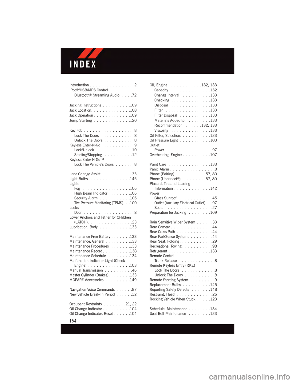
Lane Change Assist...........33Light Bulbs . . . . . . . . . . . . . . .145LightsFog . . . . . . . . . . . . . . . . .106High Beam Indicator . . . . . . .106Security Alarm...........106Ti r e P r e s s u r e M o n i t o r i n g ( T P M S )..100LocksDoor..................8Lower Anchors and Tether for CHildren(LATCH)................23Lubrication, Body...........133
Maintenance Free Battery . . . . . . .133Maintenance, General.........133Maintenance Procedures.......133Maintenance Record..........138Maintenance Schedule........134Malfunction Indicator Light (CheckEngine)...............103Manual Transmission..........46Master Cylinder (Brakes)........133MOPAR®Accessories.........149
Navigation Voice Commands......87New Vehicle Break-In Period . . . . . .32
Occupant Restraints........21,22Oil Change Indicator..........104Oil Change Indicator, Reset......104
Oil, Engine............132, 133
Capacity..............132
Change Interval..........133
Checking..............133
Disposal..............133
Filter................133
Filter Disposal...........133
Materials Added to........133
Recommendation......132, 133
Viscosity..............133
Oil Filter, Selection...........133Oil Pressure Light . . . . . . . . . . .103OutletPower................97Overheating, Engine..........107
Paint Care . . . . . . . . . . . . . . .133Panic Alarm................8Phone (Pairing)...........57,80Phone (Uconnect®). . . . . . . . .57,80Placard, Tire and LoadingInformation . . . . . . . . . . . . .142PowerGlass Sunroof............45Outlet (Auxiliary Electrical Outlet)..97Seats................27Preparation for Jacking........109
Rain Sensitive Wiper System......33Rear Camera...............44Rear Cross Path.............44Rear ParkSense System.........44Rear Seat, Folding............29Recreational Towing...........98Refrigerant . . . . . . . . . . . . . . .133Remote ControlTr u n k R e l e a s e . . . . . . . . . . . . 8Remote Keyless Entry (RKE)Lock The Doors............8Unlock The Doors...........8Remote Starting System.........9Replacement Bulbs..........145Reporting Safety Defects.......148Restraint, Head.............26Rocking Vehicle When Stuck.....123
Schedule, Maintenance........134Seat Belt Maintenance........133
INDEX
154