Battery DODGE DURANGO 1998 1.G User Guide
[x] Cancel search | Manufacturer: DODGE, Model Year: 1998, Model line: DURANGO, Model: DODGE DURANGO 1998 1.GPages: 193, PDF Size: 5.65 MB
Page 36 of 193
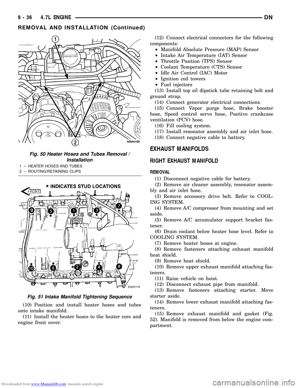
Downloaded from www.Manualslib.com manuals search engine (10) Position and install heater hoses and tubes
onto intake manifold.
(11) Install the heater hoses to the heater core and
engine front cover.(12) Connect electrical connectors for the following
components:
²Manifold Absolute Pressure (MAP) Sensor
²Intake Air Temperature (IAT) Sensor
²Throttle Position (TPS) Sensor
²Coolant Temperature (CTS) Sensor
²Idle Air Control (IAC) Motor
²Ignition coil towers
²Fuel injectors
(13) Install top oil dipstick tube retaining bolt and
ground strap.
(14) Connect generator electrical connections.
(15) Connect Vapor purge hose, Brake booster
hose, Speed control servo hose, Positive crankcase
ventilation (PCV) hose.
(16) Fill cooling system.
(17) Install resonator assembly and air inlet hose.
(18) Connect negative cable to battery.
EXHAUST MANIFOLDS
RIGHT EXHAUST MANIFOLD
REMOVAL
(1) Disconnect negative cable for battery.
(2) Remove air cleaner assembly, resonator assem-
bly and air inlet hose.
(3) Remove accessory drive belt. Refer to COOL-
ING SYSTEM.
(4) Remove A/C compressor from mounting and set
aside.
(5) Remove A/C accumulator support bracket fas-
tener.
(6) Drain coolant below heater hose level. Refer to
COOLING SYSTEM.
(7) Remove heater hoses at engine.
(8) Remove fasteners attaching exhaust manifold
heat shield.
(9) Remove heat shield.
(10) Remove upper exhaust manifold attaching fas-
teners.
(11) Raise vehicle on hoist.
(12) Disconnect exhaust pipe from manifold.
(13) Remove fasteners attaching starter. Move
starter aside.
(14) Remove lower exhaust manifold attaching fas-
teners.
(15) Remove exhaust manifold and gasket (Fig.
52). Manifold is removed from below the engine com-
partment.
Fig. 50 Heater Hoses and Tubes Removal /
Installation
1 ± HEATER HOSES AND TUBES
2 ± ROUTING/RETAINING CLIPS
Fig. 51 Intake Manifold Tightening Sequence
9 - 36 4.7L ENGINEDN
REMOVAL AND INSTALLATION (Continued)
Page 38 of 193
Downloaded from www.Manualslib.com manuals search engine (9) Install A/C compressor and fasteners.
(10) Install accessory drive belt.
(11) Install air cleaner assembly, resonator assem-
bly and air inlet hose.
(12) Install battery and connect cables.
(13) Fill cooling system.
LEFT EXHAUST MANIFOLD
REMOVAL
(1) Disconnect negative cable for battery.
(2) Hoist vehicle.
(3) Disconnect exhaust pipe at manifold.
(4) Lower vehicle.
(5) Remove the front two exhaust heat shield
retaining fasteners. Raise vehicle and remove the
fasteners at rear of heat shield.
(6) Remove heat shield (Fig. 53).
(7) Lower vehicle and remove the upper exhaust
manifold retaining bolts (Fig. 53).
(8) Raise vehicle and remove the lower exhaust
manifold retaining bolts (Fig. 53).
(9) Remove exhaust manifold and gasket (Fig. 53).
Manifold is removed from below the engine compart-
ment.
INSTALLATION
(1) Install exhaust manifold and gasket from below
engine compartment.
(2) Install lower exhaust manifold fasteners (Fig.
53). DO NOT tighten until all fasteners are in place.
(3) Lower vehicle and install upper exhaust mani-
fold fasteners (Fig. 53). Tighten all manifold bolts
starting at center and working outward to 25 N´m
(18 ft. lbs.).
CAUTION: Over tightening heat shield fasteners,
may cause shield to distort and/or crack.
(4) Install exhaust manifold heat shield (Fig. 53).
Tighten fasteners to 8 N´m (72 in. lbs.), then loosen
45 degrees.
(5) Connect exhaust pipe to manifold.
(6) Connect negative cable to battery.
CYLINDER HEAD COVER
REMOVAL
LEFT SIDE COVER
(1) Disconnect negative cable from battery.
(2) Remove the resonator assemble and air inlet
hose.
(3) Disconnect injector connectors and un-clip the
injector harness.
(4) Route injector harness in front of cylinder head
cover.(5) Disconnect the left side breather tube and
remove the breather tube.
(6) Remove the cylinder head cover mounting
bolts.
(7) Remove cylinder head cover and gasket.
NOTE: The gasket may be used again, provided no
cuts, tears, or deformation has occurred.
INSTALLATION
CAUTION: Do not use harsh cleaners to clean the
cylinder head covers. Severe damage to covers
may occur.
CAUTION: DO NOT allow other components includ-
ing the wire harness to rest on or against the cylin-
der head cover. Prolonged contact with other
objects may wear a hole in the engine cylinder head
cover.
(1) Clean cylinder head cover and both sealing sur-
faces. Inspect and replace gasket as necessary.
(2) Install cylinder head cover and hand start all
fasteners. Verify that all studs are in the correct loca-
tion shown in (Fig. 54).
(3) Tighten cylinder head cover bolts and double
ended studs to 12 N´m (105 in. lbs.).
(4) Install left side breather and connect breather
tube.
(5) Connect injector electrical connectors and injec-
tor harness retaining clips.
(6) Install the resonator and air inlet hose.
(7) Connect negative cable to battery.
REMOVAL
RIGHT SIDE COVER
(1) Disconnect battery negative cable.
(2) Remove air cleaner assembly, resonator assem-
bly and air inlet hose.
(3) Drain cooling system, below the level of the
heater hoses. Refer to COOLING SYSTEM.
(4) Remove accessory drive belt.
(5) Remove air conditioning compressor retaining
bolts and move compressor to the left.
(6) Remove heater hoses.
(7) Disconnect injector and ignition coil connectors.
(8) Disconnect and remove positive crankcase ven-
tilation (PCV) hose.
(9) Remove oil fill tube.
(10) Un-clip injector and ignition coil harness and
move away from cylinder head cover.
(11) Remove right rear breather tube and filter
assembly.
9 - 38 4.7L ENGINEDN
REMOVAL AND INSTALLATION (Continued)
Page 40 of 193
Downloaded from www.Manualslib.com manuals search engine CAUTION: DO NOT allow other components includ-
ing the wire harness to rest on or against the
engine cylinder head cover. Prolonged contact with
other objects may wear a hole in the cylinder head
cover.
(1) Clean cylinder head cover and both sealing sur-
faces. Inspect and replace gasket as necessary.
(2) Install cylinder head cover and hand start all
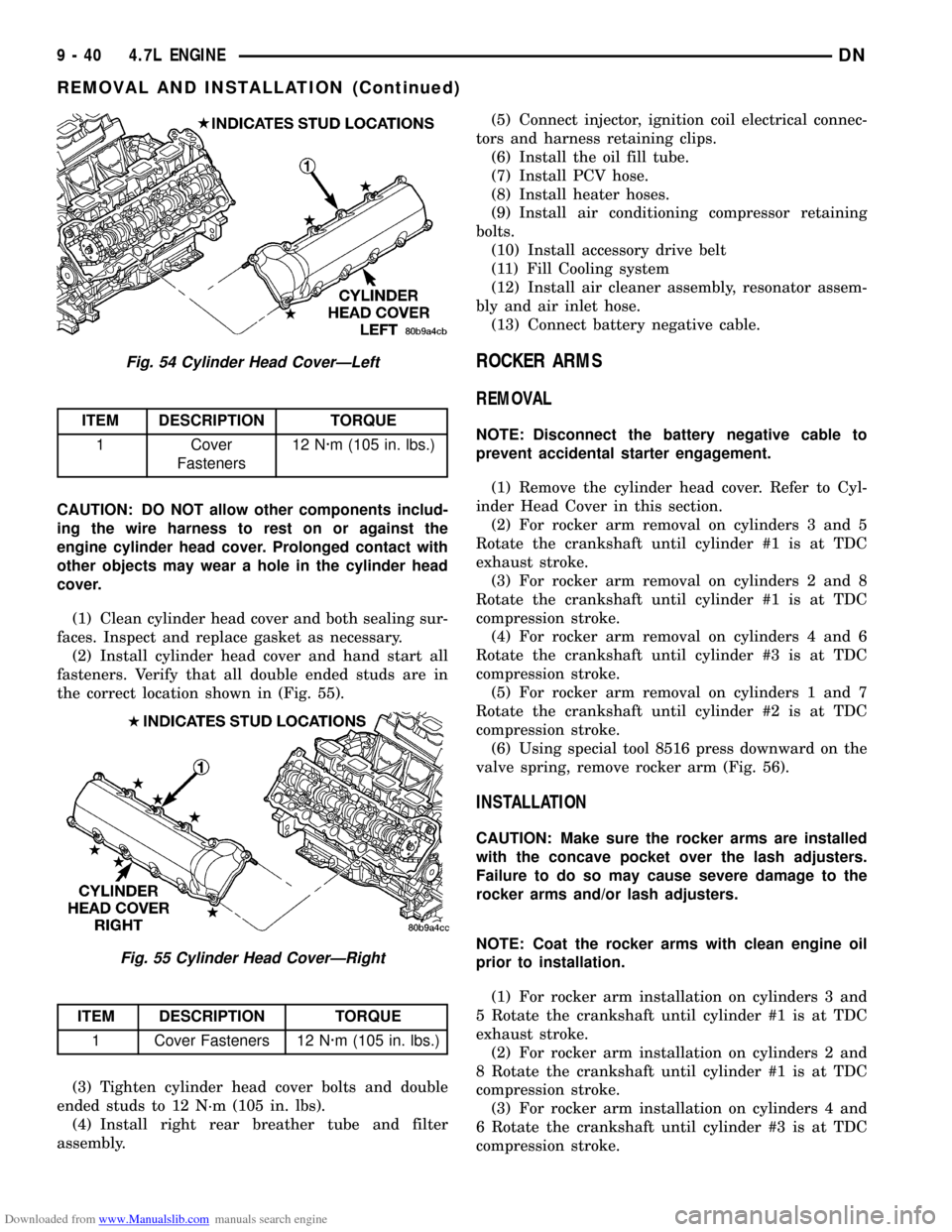
fasteners. Verify that all double ended studs are in
the correct location shown in (Fig. 55).
(3) Tighten cylinder head cover bolts and double
ended studs to 12 N´m (105 in. lbs).
(4) Install right rear breather tube and filter
assembly.(5) Connect injector, ignition coil electrical connec-
tors and harness retaining clips.
(6) Install the oil fill tube.
(7) Install PCV hose.
(8) Install heater hoses.
(9) Install air conditioning compressor retaining
bolts.
(10) Install accessory drive belt
(11) Fill Cooling system
(12) Install air cleaner assembly, resonator assem-
bly and air inlet hose.
(13) Connect battery negative cable.
ROCKER ARMS
REMOVAL
NOTE: Disconnect the battery negative cable to
prevent accidental starter engagement.
(1) Remove the cylinder head cover. Refer to Cyl-
inder Head Cover in this section.
(2) For rocker arm removal on cylinders 3 and 5
Rotate the crankshaft until cylinder #1 is at TDC
exhaust stroke.
(3) For rocker arm removal on cylinders 2 and 8
Rotate the crankshaft until cylinder #1 is at TDC
compression stroke.
(4) For rocker arm removal on cylinders 4 and 6
Rotate the crankshaft until cylinder #3 is at TDC
compression stroke.
(5) For rocker arm removal on cylinders 1 and 7
Rotate the crankshaft until cylinder #2 is at TDC
compression stroke.
(6) Using special tool 8516 press downward on the
valve spring, remove rocker arm (Fig. 56).
INSTALLATION
CAUTION: Make sure the rocker arms are installed
with the concave pocket over the lash adjusters.
Failure to do so may cause severe damage to the
rocker arms and/or lash adjusters.
NOTE: Coat the rocker arms with clean engine oil
prior to installation.
(1) For rocker arm installation on cylinders 3 and
5 Rotate the crankshaft until cylinder #1 is at TDC
exhaust stroke.
(2) For rocker arm installation on cylinders 2 and
8 Rotate the crankshaft until cylinder #1 is at TDC
compression stroke.
(3) For rocker arm installation on cylinders 4 and
6 Rotate the crankshaft until cylinder #3 is at TDC
compression stroke.
Fig. 54 Cylinder Head CoverÐLeft
ITEM DESCRIPTION TORQUE
1 Cover
Fasteners12 N´m (105 in. lbs.)
Fig. 55 Cylinder Head CoverÐRight
ITEM DESCRIPTION TORQUE
1 Cover Fasteners 12 N´m (105 in. lbs.)
9 - 40 4.7L ENGINEDN
REMOVAL AND INSTALLATION (Continued)
Page 41 of 193
Downloaded from www.Manualslib.com manuals search engine (4) For rocker arm installation on cylinders 1 and
7 Rotate the crankshaft until cylinder #2 is at TDC
compression stroke.
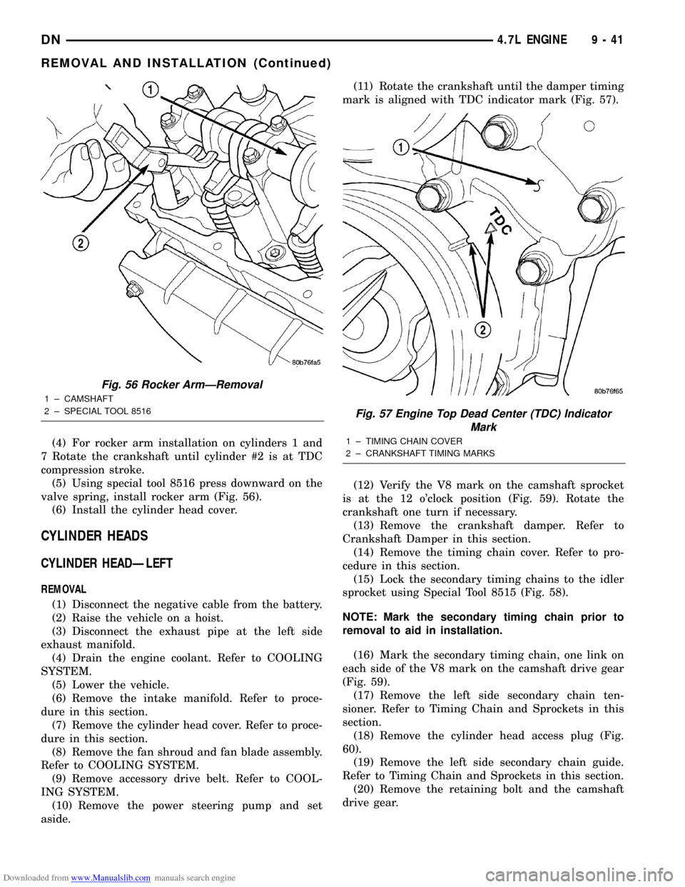
(5) Using special tool 8516 press downward on the
valve spring, install rocker arm (Fig. 56).
(6) Install the cylinder head cover.
CYLINDER HEADS
CYLINDER HEADÐLEFT
REMOVAL
(1) Disconnect the negative cable from the battery.
(2) Raise the vehicle on a hoist.
(3) Disconnect the exhaust pipe at the left side
exhaust manifold.
(4) Drain the engine coolant. Refer to COOLING
SYSTEM.
(5) Lower the vehicle.
(6) Remove the intake manifold. Refer to proce-
dure in this section.
(7) Remove the cylinder head cover. Refer to proce-
dure in this section.
(8) Remove the fan shroud and fan blade assembly.
Refer to COOLING SYSTEM.
(9) Remove accessory drive belt. Refer to COOL-
ING SYSTEM.
(10) Remove the power steering pump and set
aside.(11) Rotate the crankshaft until the damper timing
mark is aligned with TDC indicator mark (Fig. 57).
(12) Verify the V8 mark on the camshaft sprocket
is at the 12 o'clock position (Fig. 59). Rotate the
crankshaft one turn if necessary.
(13) Remove the crankshaft damper. Refer to
Crankshaft Damper in this section.
(14) Remove the timing chain cover. Refer to pro-
cedure in this section.
(15) Lock the secondary timing chains to the idler
sprocket using Special Tool 8515 (Fig. 58).
NOTE: Mark the secondary timing chain prior to
removal to aid in installation.
(16) Mark the secondary timing chain, one link on
each side of the V8 mark on the camshaft drive gear
(Fig. 59).
(17) Remove the left side secondary chain ten-
sioner. Refer to Timing Chain and Sprockets in this
section.
(18) Remove the cylinder head access plug (Fig.
60).
(19) Remove the left side secondary chain guide.
Refer to Timing Chain and Sprockets in this section.
(20) Remove the retaining bolt and the camshaft
drive gear.
Fig. 56 Rocker ArmÐRemoval
1 ± CAMSHAFT
2 ± SPECIAL TOOL 8516
Fig. 57 Engine Top Dead Center (TDC) Indicator
Mark
1 ± TIMING CHAIN COVER
2 ± CRANKSHAFT TIMING MARKS
DN4.7L ENGINE 9 - 41
REMOVAL AND INSTALLATION (Continued)
Page 44 of 193
Downloaded from www.Manualslib.com manuals search engine (14) Install the crankshaft damper. Tighten
damper bolt 175 N´m (130 Ft. Lbs.).
(15) Install the power steering pump.
(16) Install the fan blade assembly and fan
shroud.
(17) Install the cylinder head cover.
(18) Install the intake manifold.
(19) Refill the cooling system
(20) Raise the vehicle.
(21) Install the exhaust pipe onto the left exhaust
manifold.
(22) Lower the vehicle.
(23) Connect the negative cable to the battery.
(24) Start the engine and check for leaks.
CYLINDER HEADÐRIGHT
REMOVAL
(1) Disconnect battery negitive cable.
(2) Raise the vehicle on a hoist.
(3) Disconnect the exhaust pipe at the right side
exhaust manifold.
(4) Drain the engine coolant. Refer to COOLING
SYSTEM.
(5) Lower the vehicle.
(6) Remove the intake manifold. Refer to proce-
dure in this section.
(7) Remove the cylinder head cover. Refer to proce-
dure in this section.
(8) Remove the fan shroud. Refer to COOLING
SYSTEM.
(9) Remove oil fill housing from cylinder head.
(10) Remove accessory drive belt. Refer to COOL-
ING SYSTEM.
(11) Rotate the crankshaft until the damper timing
mark is aligned with TDC indicator mark (Fig. 57).
(12) Verify the V8 mark on the camshaft sprocket
is at the 12 o'clock position (Fig. 59). Rotate the
crankshaft one turn if necessary.
(13) Remove the crankshaft damper. Refer to
Crankshaft Damper in this section.(14) Remove the timing chain cover. Refer to Tim-
ing Chain Cover in this section.
(15) Lock the secondary timing chains to the idler
sprocket using Special Tool 8515 (Fig. 58).
NOTE: Mark the secondary timing chain prior to
removal to aid in installation.
(16) Mark the secondary timing chain, one link on
each side of the V8 mark on the camshaft drive gear
(Fig. 59).
(17) Remove the right side secondary chain ten-
sioner. Refer to Timing Chain and Sprockets in this
section.
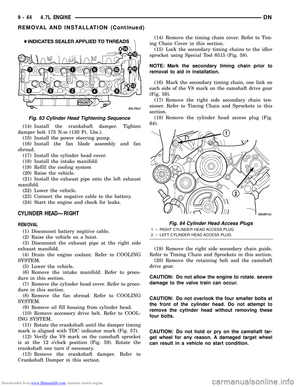
(18) Remove the cylinder head access plug (Fig.
64).
(19) Remove the right side secondary chain guide.
Refer to Timing Chain and Sprockets in this section.
(20) Remove the retaining bolt and the camshaft
drive gear.
CAUTION: Do not allow the engine to rotate. severe
damage to the valve train can occur.
CAUTION: Do not overlook the four smaller bolts at
the front of the cylinder head. Do not attempt to
remove the cylinder head without removing these
four bolts.
CAUTION: Do not hold or pry on the camshaft tar-
get wheel for any reason. A damaged target wheel
can result in a vehicle no start condition.
Fig. 63 Cylinder Head Tightening Sequence
Fig. 64 Cylinder Head Access Plugs
1 ± RIGHT CYLINDER HEAD ACCESS PLUG
2 ± LEFT CYLINDER HEAD ACCESS PLUG
9 - 44 4.7L ENGINEDN
REMOVAL AND INSTALLATION (Continued)
Page 46 of 193
Downloaded from www.Manualslib.com manuals search engine (14) Install the crankshaft damper. Tighten
damper bolt 175 N´m (130 Ft. Lbs.).
(15) Install accessory drive belt.
(16) Install the fan shroud.
(17) Install the cylinder head cover.
(18) Install the intake manifold.
(19) Install oil fill housing onto cylinder head.
(20) Refill the cooling system.
(21) Raise the vehicle.
(22) Install the exhaust pipe onto the right
exhaust manifold.
(23) Lower the vehicle.
(24) Reconnect battery negitive cable.
(25) Start the engine and check for leaks.
VALVE SPRINGS AND SEALS
REMOVAL
(1) Remove the cylinder head cover. Refer to Cyl-
inder Head Cover in this Section.
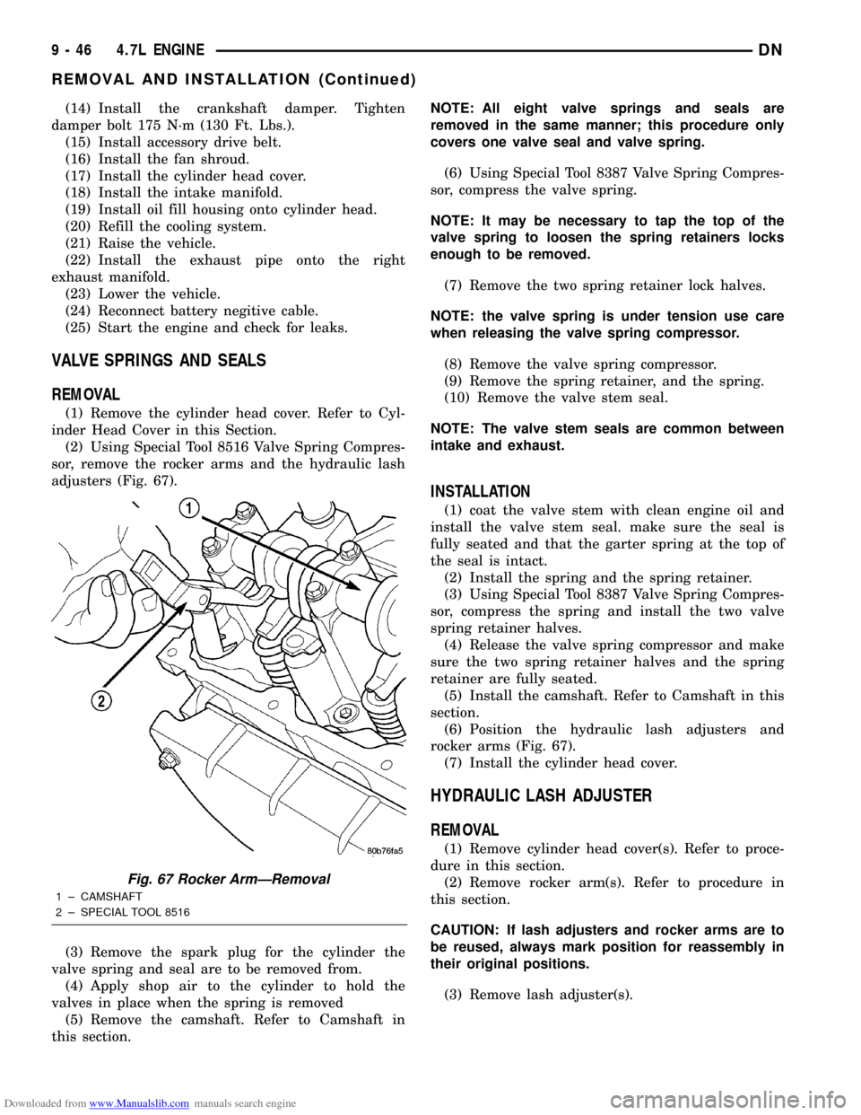
(2) Using Special Tool 8516 Valve Spring Compres-
sor, remove the rocker arms and the hydraulic lash
adjusters (Fig. 67).
(3) Remove the spark plug for the cylinder the
valve spring and seal are to be removed from.
(4) Apply shop air to the cylinder to hold the
valves in place when the spring is removed
(5) Remove the camshaft. Refer to Camshaft in
this section.NOTE: All eight valve springs and seals are
removed in the same manner; this procedure only
covers one valve seal and valve spring.
(6) Using Special Tool 8387 Valve Spring Compres-
sor, compress the valve spring.
NOTE: It may be necessary to tap the top of the
valve spring to loosen the spring retainers locks
enough to be removed.
(7) Remove the two spring retainer lock halves.
NOTE: the valve spring is under tension use care
when releasing the valve spring compressor.
(8) Remove the valve spring compressor.
(9) Remove the spring retainer, and the spring.
(10) Remove the valve stem seal.
NOTE: The valve stem seals are common between
intake and exhaust.
INSTALLATION
(1) coat the valve stem with clean engine oil and
install the valve stem seal. make sure the seal is
fully seated and that the garter spring at the top of
the seal is intact.
(2) Install the spring and the spring retainer.
(3) Using Special Tool 8387 Valve Spring Compres-
sor, compress the spring and install the two valve
spring retainer halves.
(4) Release the valve spring compressor and make
sure the two spring retainer halves and the spring
retainer are fully seated.
(5) Install the camshaft. Refer to Camshaft in this
section.
(6) Position the hydraulic lash adjusters and
rocker arms (Fig. 67).
(7) Install the cylinder head cover.
HYDRAULIC LASH ADJUSTER
REMOVAL
(1) Remove cylinder head cover(s). Refer to proce-
dure in this section.
(2) Remove rocker arm(s). Refer to procedure in
this section.
CAUTION: If lash adjusters and rocker arms are to
be reused, always mark position for reassembly in
their original positions.
(3) Remove lash adjuster(s).
Fig. 67 Rocker ArmÐRemoval
1 ± CAMSHAFT
2 ± SPECIAL TOOL 8516
9 - 46 4.7L ENGINEDN
REMOVAL AND INSTALLATION (Continued)
Page 47 of 193
Downloaded from www.Manualslib.com manuals search engine INSTALLATION
(1) Install hydraulic lash adjuster making sure
adjusters are at least partially full of oil. This can be
verified by little or no plunger travel when lash
adjuster is depressed.
(2) Install rocker arm(s). Refer to procedure in this
section.
(3) Install cylinder head cover(s). Refer to proce-
dure in this section.
CRANKSHAFT DAMPER
REMOVAL
(1) Disconnect negative cable from battery.
(2) Remove accessory drive belt. Refer to COOL-
ING SYSTEM.
(3) Drain cooling system. Refer to COOLING SYS-
TEM.
(4) Remove radiator upper hose.
(5) Remove upper fan shroud. Refer to COOLING
SYSTEM.
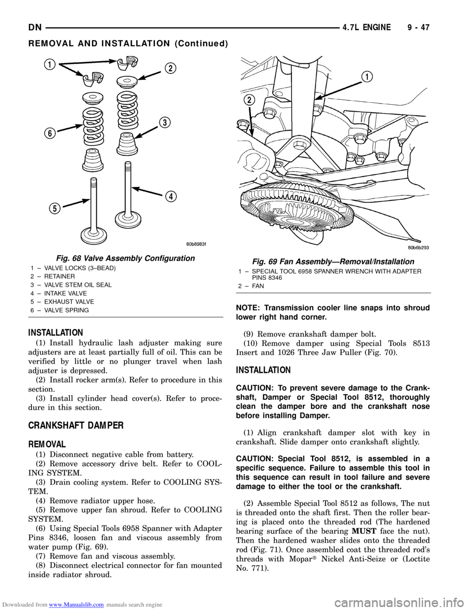
(6) Using Special Tools 6958 Spanner with Adapter
Pins 8346, loosen fan and viscous assembly from
water pump (Fig. 69).
(7) Remove fan and viscous assembly.
(8) Disconnect electrical connector for fan mounted
inside radiator shroud.NOTE: Transmission cooler line snaps into shroud
lower right hand corner.
(9) Remove crankshaft damper bolt.
(10) Remove damper using Special Tools 8513
Insert and 1026 Three Jaw Puller (Fig. 70).
INSTALLATION
CAUTION: To prevent severe damage to the Crank-
shaft, Damper or Special Tool 8512, thoroughly
clean the damper bore and the crankshaft nose
before installing Damper.
(1) Align crankshaft damper slot with key in
crankshaft. Slide damper onto crankshaft slightly.
CAUTION: Special Tool 8512, is assembled in a
specific sequence. Failure to assemble this tool in
this sequence can result in tool failure and severe
damage to either the tool or the crankshaft.
(2) Assemble Special Tool 8512 as follows, The nut
is threaded onto the shaft first. Then the roller bear-
ing is placed onto the threaded rod (The hardened
bearing surface of the bearingMUSTface the nut).
Then the hardened washer slides onto the threaded
rod (Fig. 71). Once assembled coat the threaded rod's
threads with MopartNickel Anti-Seize or (Loctite
No. 771).
Fig. 68 Valve Assembly Configuration
1 ± VALVE LOCKS (3±BEAD)
2 ± RETAINER
3 ± VALVE STEM OIL SEAL
4 ± INTAKE VALVE
5 ± EXHAUST VALVE
6 ± VALVE SPRINGFig. 69 Fan AssemblyÐRemoval/Installation
1 ± SPECIAL TOOL 6958 SPANNER WRENCH WITH ADAPTER
PINS 8346
2±FAN
DN4.7L ENGINE 9 - 47
REMOVAL AND INSTALLATION (Continued)
Page 48 of 193
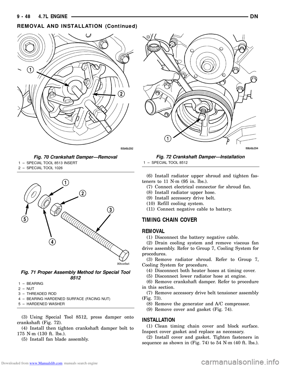
Downloaded from www.Manualslib.com manuals search engine (3) Using Special Tool 8512, press damper onto
crankshaft (Fig. 72).
(4) Install then tighten crankshaft damper bolt to
175 N´m (130 ft. lbs.).
(5) Install fan blade assembly.(6) Install radiator upper shroud and tighten fas-
teners to 11 N´m (95 in. lbs.).
(7) Connect electrical connector for shroud fan.
(8) Install radiator upper hose.
(9) Install accessory drive belt.
(10) Refill cooling system.
(11) Connect negative cable to battery.
TIMING CHAIN COVER
REMOVAL
(1) Disconnect the battery negative cable.
(2) Drain cooling system and remove viscous fan
drive assembly. Refer to Group 7, Cooling System for
procedures.
(3) Remove radiator shroud. Refer to Group 7,
Cooling System for procedure.
(4) Disconnect both heater hoses at timing cover.
(5) Disconnect lower radiator hose at engine.
(6) Remove crankshaft damper. Refer to procedure
in this section.
(7) Remove accessory drive belt tensioner assembly
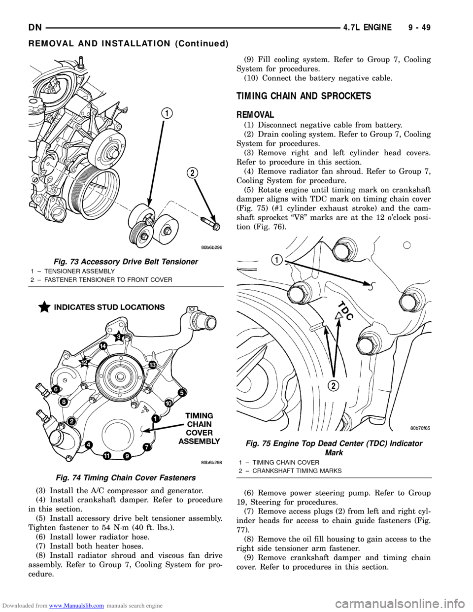
(Fig. 73).
(8) Remove the generator and A/C compressor.
(9) Remove cover and gasket (Fig. 74).
INSTALLATION
(1) Clean timing chain cover and block surface.
Inspect cover gasket and replace as necessary.
(2) Install cover and gasket. Tighten fasteners in
sequence as shown in (Fig. 74) to 54 N´m (40 ft. lbs.).
Fig. 70 Crankshaft DamperÐRemoval
1 ± SPECIAL TOOL 8513 INSERT
2 ± SPECIAL TOOL 1026
Fig. 71 Proper Assembly Method for Special Tool
8512
1 ± BEARING
2 ± NUT
3 ± THREADED ROD
4 ± BEARING HARDENED SURFACE (FACING NUT)
5 ± HARDENED WASHER
Fig. 72 Crankshaft DamperÐInstallation
1 ± SPECIAL TOOL 8512
9 - 48 4.7L ENGINEDN
REMOVAL AND INSTALLATION (Continued)
Page 49 of 193
Downloaded from www.Manualslib.com manuals search engine (3) Install the A/C compressor and generator.
(4) Install crankshaft damper. Refer to procedure
in this section.
(5) Install accessory drive belt tensioner assembly.
Tighten fastener to 54 N´m (40 ft. lbs.).
(6) Install lower radiator hose.
(7) Install both heater hoses.
(8) Install radiator shroud and viscous fan drive
assembly. Refer to Group 7, Cooling System for pro-
cedure.(9) Fill cooling system. Refer to Group 7, Cooling
System for procedures.
(10) Connect the battery negative cable.
TIMING CHAIN AND SPROCKETS
REMOVAL
(1) Disconnect negative cable from battery.
(2) Drain cooling system. Refer to Group 7, Cooling
System for procedures.
(3) Remove right and left cylinder head covers.
Refer to procedure in this section.
(4) Remove radiator fan shroud. Refer to Group 7,
Cooling System for procedure.
(5) Rotate engine until timing mark on crankshaft
damper aligns with TDC mark on timing chain cover
(Fig. 75) (#1 cylinder exhaust stroke) and the cam-
shaft sprocket ªV8º marks are at the 12 o'clock posi-
tion (Fig. 76).
(6) Remove power steering pump. Refer to Group
19, Steering for procedures.
(7) Remove access plugs (2) from left and right cyl-
inder heads for access to chain guide fasteners (Fig.
77).
(8) Remove the oil fill housing to gain access to the
right side tensioner arm fastener.
(9) Remove crankshaft damper and timing chain
cover. Refer to procedures in this section.
Fig. 73 Accessory Drive Belt Tensioner
1 ± TENSIONER ASSEMBLY
2 ± FASTENER TENSIONER TO FRONT COVER
Fig. 74 Timing Chain Cover Fasteners
Fig. 75 Engine Top Dead Center (TDC) Indicator
Mark
1 ± TIMING CHAIN COVER
2 ± CRANKSHAFT TIMING MARKS
DN4.7L ENGINE 9 - 49
REMOVAL AND INSTALLATION (Continued)
Page 51 of 193
Downloaded from www.Manualslib.com manuals search engine CAUTION: Care should be taken not to damage
camshaft target wheel. Do not hold target wheel
while loosening or tightening camshaft sprocket.
Do not place the target wheel near a magnetic
source of any kind. A damaged or magnetized tar-
get wheel could cause a vehicle no start condition.
CAUTION: Do not forcefully rotate the camshafts or
crankshaft independently of each other. Damaging
intake valve to piston contact will occur. Ensure
negative battery cable is disconnected to guard
against accidental starter engagement.
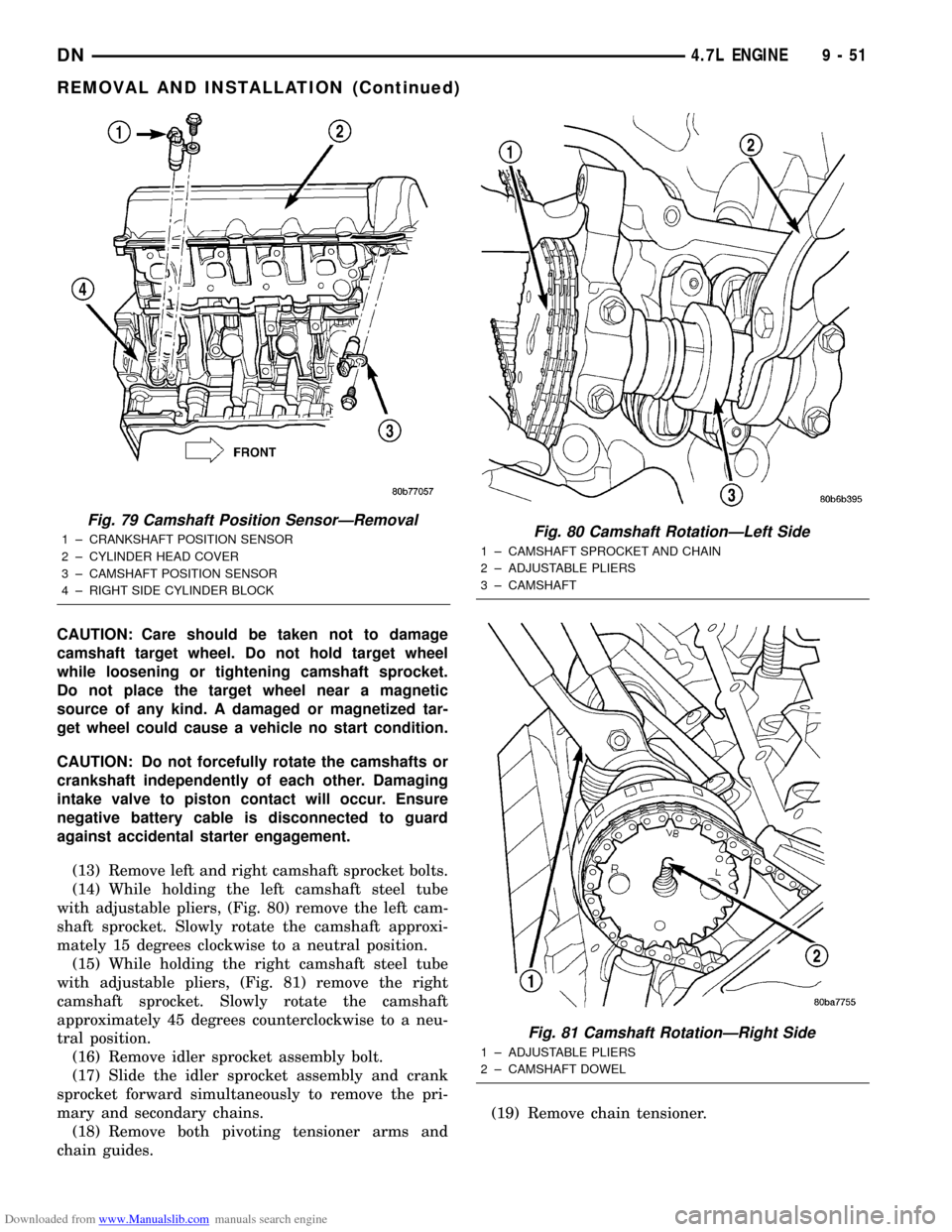
(13) Remove left and right camshaft sprocket bolts.
(14) While holding the left camshaft steel tube
with adjustable pliers, (Fig. 80) remove the left cam-
shaft sprocket. Slowly rotate the camshaft approxi-
mately 15 degrees clockwise to a neutral position.
(15) While holding the right camshaft steel tube
with adjustable pliers, (Fig. 81) remove the right
camshaft sprocket. Slowly rotate the camshaft
approximately 45 degrees counterclockwise to a neu-
tral position.
(16) Remove idler sprocket assembly bolt.
(17) Slide the idler sprocket assembly and crank
sprocket forward simultaneously to remove the pri-
mary and secondary chains.
(18) Remove both pivoting tensioner arms and
chain guides.(19) Remove chain tensioner.
Fig. 79 Camshaft Position SensorÐRemoval
1 ± CRANKSHAFT POSITION SENSOR
2 ± CYLINDER HEAD COVER
3 ± CAMSHAFT POSITION SENSOR
4 ± RIGHT SIDE CYLINDER BLOCKFig. 80 Camshaft RotationÐLeft Side
1 ± CAMSHAFT SPROCKET AND CHAIN
2 ± ADJUSTABLE PLIERS
3 ± CAMSHAFT
Fig. 81 Camshaft RotationÐRight Side
1 ± ADJUSTABLE PLIERS
2 ± CAMSHAFT DOWEL
DN4.7L ENGINE 9 - 51
REMOVAL AND INSTALLATION (Continued)