Battery DODGE DURANGO 1998 1.G Owner's Manual
[x] Cancel search | Manufacturer: DODGE, Model Year: 1998, Model line: DURANGO, Model: DODGE DURANGO 1998 1.GPages: 193, PDF Size: 5.65 MB
Page 55 of 193
Downloaded from www.Manualslib.com manuals search engine (24) Coat the large threaded access plug with
MopartThread Sealant with Teflon, then install
into the right cylinder head and tighten to 81 N´m
(60 ft. lbs.) (Fig. 77).(25) Install the oil fill housing.
(26) Install access plug in left cylinder head (Fig.
77).
(27) Install power steering pump. Refer to Group
19, Steering for procedure.
(28) Install radiator fan shroud. Refer to Group 7,
Cooling System for procedure.
(29) Fill cooling system. Refer to Group 7, Cooling
System for coolant fill procedure.
(30) Connect negative cable to battery.
IDLER SHAFTÐTIMING DRIVE
REMOVAL
(1) Remove the timing chain and sprockets. Refer
to procedure in this section.
NOTE: To remove the idler shaft, it is necessary to
tap threads into the shaft to install the removal tool.
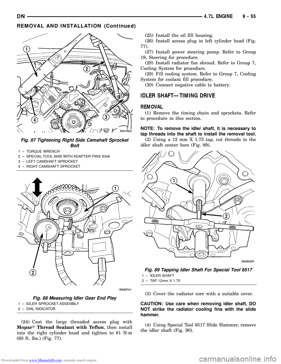
(2) Using a 12 mm X 1.75 tap, cut threads in the
idler shaft center bore (Fig. 89).
(3) Cover the radiator core with a suitable cover.
CAUTION: Use care when removing idler shaft, DO
NOT strike the radiator cooling fins with the slide
hammer.
(4) Using Special Tool 8517 Slide Hammer, remove
the idler shaft (Fig. 90).
Fig. 87 Tightening Right Side Camshaft Sprocket
Bolt
1 ± TORQUE WRENCH
2 ± SPECIAL TOOL 6958 WITH ADAPTER PINS 8346
3 ± LEFT CAMSHAFT SPROCKET
4 ± RIGHT CAMSHAFT SPROCKET
Fig. 88 Measuring Idler Gear End Play
1 ± IDLER SPROCKET ASSEMBLY
2 ± DIAL INDICATOR
Fig. 89 Tapping Idler Shaft For Special Tool 8517
1 ± IDLER SHAFT
2 ± TAP 12mm X 1.75
DN4.7L ENGINE 9 - 55
REMOVAL AND INSTALLATION (Continued)
Page 65 of 193
Downloaded from www.Manualslib.com manuals search engine INSTALLATION
(1) Clean the oil pan gasket mating surface of the
bedplate and oil pan.
(2) Position the oil pan gasket and pickup tube
with new o-ring. Install the mounting bolt and nuts.
Tighten bolt and nuts to 28 N´m (20 ft. lbs.).
(3) Position the oil pan and install the mounting
bolts. Tighten the mounting bolts to 15 N´m (11 ft.
lbs.) in the sequence shown (Fig. 110).
(4) Install structural dust cover.
(5) Install oil filter.
(6) Install front axle. Refer to DIFFERENTIAL
AND DRIVELINE.
(7) Lower vehicle.
(8) Fill engine oil.
(9) Start engine check for leaks.
PISTON AND CONNECTING ROD
REMOVAL
(1) Disconnect negative cable from battery.
(2) Remove the following components: (Refer to
procedures in this section)
²Oil pan and gasket/windage tray.
²Cylinder head covers.
²Timing chain cover.
²Cylinder head(s).
(3) If necessary, remove top ridge of cylinder bores
with a reliable ridge reamer before removing pistons
from cylinder block.Be sure to keep tops of pis-
tons covered during this operation.Pistons and
connecting rods must be removed from top of cylinder
block. When removing piston and connecting rod
assemblies from the engine, rotate crankshaft so the
each connecting rod is centered in cylinder bore.
CAUTION: DO NOT use a number stamp or a punch
to mark connecting rods or caps, as damage to
connecting rods could occur
NOTE: Connecting rods and bearing caps are not
interchangeable and should be marked before
removing to ensure correct reassembly.
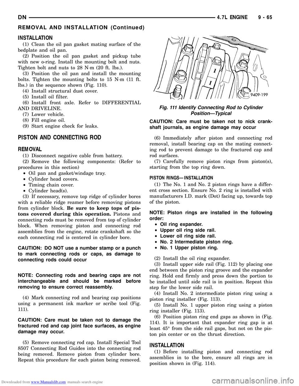
(4) Mark connecting rod and bearing cap positions
using a permanent ink marker or scribe tool (Fig.
111).
CAUTION: Care must be taken not to damage the
fractured rod and cap joint face surfaces, as engine
damage may occur.
(5) Remove connecting rod cap. Install Special Tool
8507 Connecting Rod Guides into the connecting rod
being removed. Remove piston from cylinder bore.
Repeat this procedure for each piston being removed.CAUTION: Care must be taken not to nick crank-
shaft journals, as engine damage may occur
(6) Immediately after piston and connecting rod
removal, install bearing cap on the mating connect-
ing rod to prevent damage to the fractured cap and
rod surfaces.
(7) Carefully remove piston rings from piston(s),
starting from the top ring down.
PISTON RINGSÐINSTALLATION
(1) The No. 1 and No. 2 piston rings have a differ-
ent cross section. Ensure No. 2 ring is installed with
manufacturers I.D. mark (Dot) facing up, towards top
of the piston.
NOTE: Piston rings are installed in the following
order:
²Oil ring expander.
²Upper oil ring side rail.
²Lower oil ring side rail.
²No. 2 Intermediate piston ring.
²No. 1 Upper piston ring.
(2) Install the oil ring expander.
(3) Install upper side rail (Fig. 112) by placing one
end between the piston ring groove and the expander
ring. Hold end firmly and press down the portion to
be installed until side rail is in position. Repeat this
step for the lower side rail.
(4) Install No. 2 intermediate piston ring using a
piston ring installer (Fig. 113).
(5) Install No. 1 upper piston ring using a piston
ring installer (Fig. 113).
(6) Position piston ring end gaps as shown in (Fig.
114). It is important that expander ring gap is at
least 45É from the side rail gaps, but not on the pis-
ton pin center or on the thrust direction.
INSTALLATION
(1) Before installing piston and connecting rod
assemblies in to the bore, ensure all rings are in
position shown in (Fig. 114).
Fig. 111 Identify Connecting Rod to Cylinder
PositionÐTypical
DN4.7L ENGINE 9 - 65
REMOVAL AND INSTALLATION (Continued)
Page 67 of 193
Downloaded from www.Manualslib.com manuals search engine (7) Rotate crankshaft until connecting rod journal
is on the center of cylinder bore. Insert rod and pis-
ton into cylinder bore and carefully position connect-
ing rod guides over crankshaft journal.
(8) Tap piston down in cylinder bore using a ham-
mer handle. While at the same time, guide connect-
ing rod into position on rod journal.
CAUTION: Connecting Rod Bolts are Torque to
Yield Bolts and Must Not Be Reused. Always
replace the Rod Bolts whenever they are loosened
or removed.
(9) Lubricate rod bolts and bearing surfaces with
engine oil. Install connecting rod cap and bearing.
Tighten bolts to 27 N´m (20 ft. lbs.) plus 90É.
(10) Install the following components: (Refer to
procedures in this section)
²Cylinder head(s).
²Timing chain and cover.
²Cylinder head covers.
²Oil pan and gasket/windage tray.
(11) Fill crankcase with proper engine oil to cor-
rect level.
(12) Connect negative cable to battery.
CRANKSHAFT
REMOVAL
NOTE: To remove the crankshaft from the engine,
the engine must be removed from the vehicle.
(1) Remove the engine. Refer to Engine Assembly
in this section for procedure.
(2) Remove the engine oil pump. Refer to Oil
Pump in this section for procedure.
CAUTION: DO NOT pry on the oil pan gasket when
removing the oil pan, The oil pan gasket is mounted
to the cylinder block in three locations and will
remain attached to block when removing oil pan.
Gasket can not be removed with oil pan.
(3) Remove oil pan bolts and oil pan.
(4) Remove the oil pump pickup tube and oil pan
gasket /windage tray.
(5) Remove the bedplate mounting bolts. Note the
location of the three stud bolts for installation.
(6) Remove the connecting rods from the crank-
shaft.
CAUTION: The bedplate to cylinder block mating
surface is a critical sealing surface. Do not pry on
or damage this surface in anyway.
NOTE: The bedplate contains the lower main bear-
ing halves. Use care when handling bedplate as not
to drop or damage bearing halves. Installing main
bearing halves in the wrong position will cause
sever damage to the crankshaft.
NOTE: The bedplate has pry points cast into it. Use
these points only. The pry points are on both the
left and right sides, only the left side is shown.
(7) Carefully pry on the pry points (Fig. 117) to
loosen the bedplate then remove the bedplate.
CAUTION: When removing the crankshaft, use care
not to damage bearing surfaces on the crankshaft.
(8) Remove the crankshaft.
(9) Remove the crankshaft tone wheel.
INSPECTION
NOTE: Thoroughly inspect the connecting rod
bearing bores and main bearing bores for scoring,
blueing or severe scratches. Further disassembly
may be required.
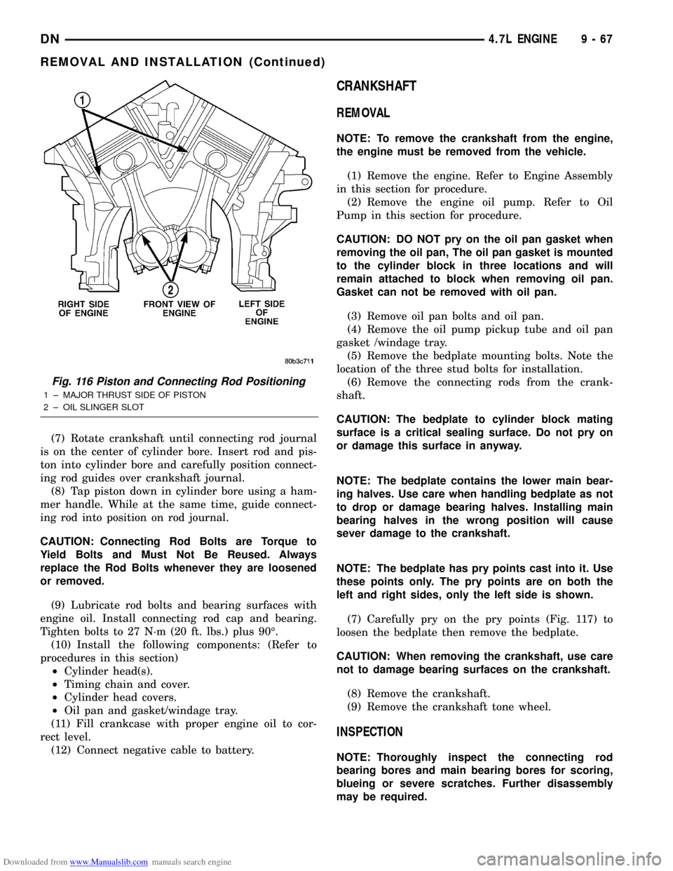
Fig. 116 Piston and Connecting Rod Positioning
1 ± MAJOR THRUST SIDE OF PISTON
2 ± OIL SLINGER SLOT
DN4.7L ENGINE 9 - 67
REMOVAL AND INSTALLATION (Continued)
Page 70 of 193
Downloaded from www.Manualslib.com manuals search engine ENGINE OIL PRESSURE SENDING UNIT
REMOVAL
(1) Disconnect the negative cable from the battery.
(2) Raise vehicle on hoist.
(3) Remove front splash shield.
(4) Disconnect oil pressure sender wire (Fig. 125).
(5) Remove the pressure sender (Fig. 125).
INSTALLATION
(1) Install oil pressure sender.
(2) Connect oil pressure sender wire.
(3) Install front splash shield.
(4) Lower vehicle.
(5) Connect the negative battery cable.CRANKSHAFT OIL SEALÐFRONT
REMOVAL
(1) Disconnect negative cable from battery.
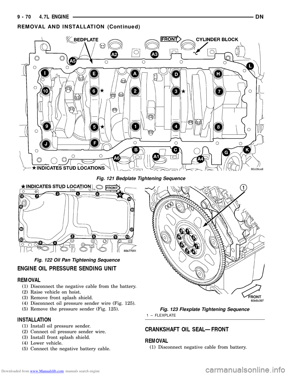
Fig. 121 Bedplate Tightening Sequence
Fig. 122 Oil Pan Tightening Sequence
Fig. 123 Flexplate Tightening Sequence
1 ± FLEXPLATE
9 - 70 4.7L ENGINEDN
REMOVAL AND INSTALLATION (Continued)
Page 72 of 193
Downloaded from www.Manualslib.com manuals search engine CAUTION: Special Tool 8512, is assembled in a
specific sequence. Failure to assemble this tool in
this sequence can result in tool failure and severe
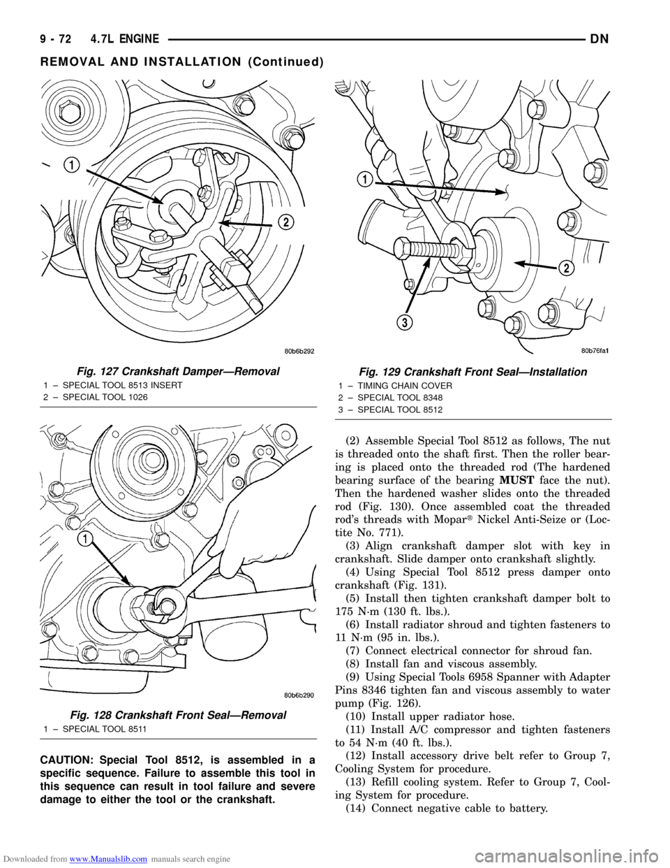
damage to either the tool or the crankshaft.(2) Assemble Special Tool 8512 as follows, The nut
is threaded onto the shaft first. Then the roller bear-
ing is placed onto the threaded rod (The hardened
bearing surface of the bearingMUSTface the nut).
Then the hardened washer slides onto the threaded
rod (Fig. 130). Once assembled coat the threaded
rod's threads with MopartNickel Anti-Seize or (Loc-
tite No. 771).
(3) Align crankshaft damper slot with key in
crankshaft. Slide damper onto crankshaft slightly.
(4) Using Special Tool 8512 press damper onto
crankshaft (Fig. 131).
(5) Install then tighten crankshaft damper bolt to
175 N´m (130 ft. lbs.).
(6) Install radiator shroud and tighten fasteners to
11 N´m (95 in. lbs.).
(7) Connect electrical connector for shroud fan.
(8) Install fan and viscous assembly.
(9) Using Special Tools 6958 Spanner with Adapter
Pins 8346 tighten fan and viscous assembly to water
pump (Fig. 126).
(10) Install upper radiator hose.
(11) Install A/C compressor and tighten fasteners
to 54 N´m (40 ft. lbs.).
(12) Install accessory drive belt refer to Group 7,
Cooling System for procedure.
(13) Refill cooling system. Refer to Group 7, Cool-
ing System for procedure.
(14) Connect negative cable to battery.
Fig. 127 Crankshaft DamperÐRemoval
1 ± SPECIAL TOOL 8513 INSERT
2 ± SPECIAL TOOL 1026
Fig. 128 Crankshaft Front SealÐRemoval
1 ± SPECIAL TOOL 8511
Fig. 129 Crankshaft Front SealÐInstallation
1 ± TIMING CHAIN COVER
2 ± SPECIAL TOOL 8348
3 ± SPECIAL TOOL 8512
9 - 72 4.7L ENGINEDN
REMOVAL AND INSTALLATION (Continued)
Page 95 of 193
Downloaded from www.Manualslib.com manuals search engine (4) A controlled hone motor speed between 200 and
300 RPM is necessary to obtain the proper cross-
hatch angle. The number of up and down strokes per
minute can be regulated to get the desired 50É to 60É
angle. Faster up and down strokes increase the cross-
hatch angle.
(5) After honing, it is necessary that the block be
cleaned to remove all traces of abrasive. Use a brush
to wash parts with a solution of hot water and deter-
gent. Dry parts thoroughly. Use a clean, white, lint-
free cloth to check that the bore is clean. Oil the
bores after cleaning to prevent rusting.
HYDROSTATIC LOCK
When an engine is suspected of hydrostatic lock
(regardless of what caused the problem), follow the
steps below.
(1) Perform the Fuel Pressure Release Procedure
(refer to Group 14, Fuel System).
(2) Disconnect the battery negative cable.
(3) Inspect air cleaner, induction system and
intake manifold to ensure system is dry and clear of
foreign material.
(4) Place a shop towel around the spark plugs to
catch any fluid that may possibly be under pressure
in the cylinder head. Remove the plugs from the
engine.
CAUTION: DO NOT use the starter motor to rotate
the crankshaft. Severe damage could occur.
(5) With all spark plugs removed, rotate the crank-
shaft using a breaker bar and socket.
(6) Identify the fluid in the cylinders (i.e. coolant,
fuel, oil, etc.).
(7) Make sure all fluid has been removed from the
cylinders.
(8) Repair engine or components as necessary to
prevent this problem from occurring again.
(9) Squirt engine oil into the cylinders to lubricate
the walls. This will prevent damage on restart.
(10) Install new spark plugs.
(11) Drain engine oil. Remove and discard the oil
filter.
(12) Install the drain plug. Tighten the plug to 34
N´m (25 ft. lbs.) torque.
(13) Install a new oil filter.
(14) Fill engine crankcase with the specified
amount and grade of oil.
(15) Connect the negative cable to the battery.
(16) Start the engine and check for any leaks.
VALVE TIMING
(1) Turn crankshaft until the No.6 exhaust valve is
closing and No.6 intake valve is opening.(2) Insert a 6.350 mm (1/4 inch) spacer between
rocker arm pad and stem tip of No.1 intake valve.
Allow spring load to bleed tappet down giving in
effect a solid tappet.
(3) Install a dial indicator so plunger contacts
valve spring retainer as nearly perpendicular as pos-
sible. Zero the indicator.
(4) Rotate the crankshaft clockwise (normal run-
ning direction) until the valve has lifted 0.863 mm
(0.034 inch). The timing of the crankshaft should
now read from 10É before top dead center to 2É after
top dead center. Remove spacer.
CAUTION: DO NOT turn crankshaft any further
clockwise as valve spring might bottom and result
in serious damage.
If reading is not within specified limits:
²Check sprocket index marks.
²Inspect timing chain for wear.
²Check accuracy of DC mark on timing indicator.
VALVE SERVICE
VALVE CLEANING
Clean valves thoroughly. Discard burned, warped
and cracked valves.
Remove carbon and varnish deposits from inside of
valve guides with a reliable guide cleaner.
VALVE INSPECTION
Measure valve stems for wear. If wear exceeds
0.051 mm (0.002 inch), replace the valve.
VALVE GUIDES
Measure valve stem guide clearance as follows:
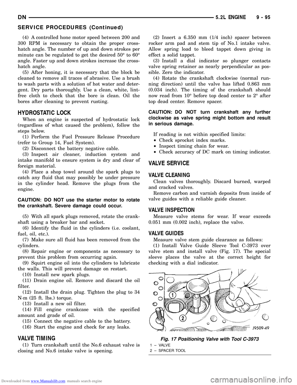
(1) Install Valve Guide Sleeve Tool C-3973 over
valve stem and install valve (Fig. 17). The special
sleeve places the valve at the correct height for
checking with a dial indicator.
Fig. 17 Positioning Valve with Tool C-3973
1 ± VALVE
2 ± SPACER TOOL
DN5.2L ENGINE 9 - 95
SERVICE PROCEDURES (Continued)
Page 101 of 193
Downloaded from www.Manualslib.com manuals search engine (1) Disconnect the negative cable from the battery.
(2) Raise vehicle on hoist.
(3) Install engine lifting (support) fixture.
(4) Remove front axle assembly. (Refer to Group 3,
Differential and Driveline in this publication.)
(5)Left mount insulator only.Remove starter
wires and starter motor assembly.
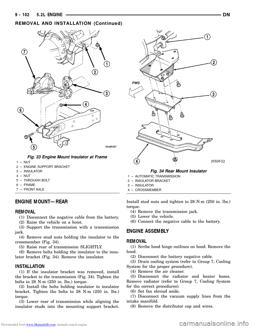
(6) Remove insulator to frame through bolt (Fig.
33).
(7) Raise engine slightly.
(8) Remove upper insulator to support bracket
stud nut and insulator to support through bolt.
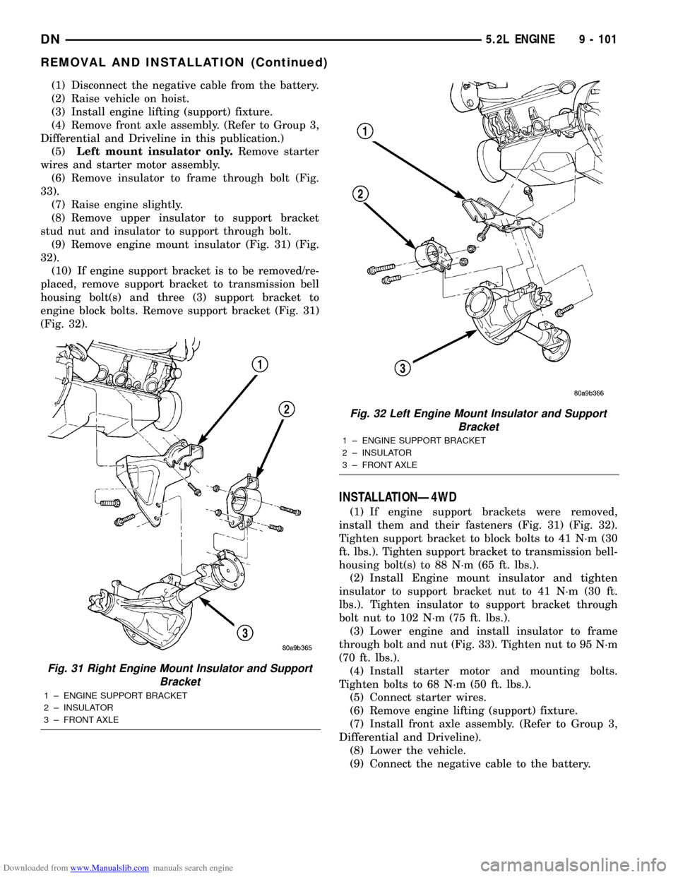
(9) Remove engine mount insulator (Fig. 31) (Fig.
32).
(10) If engine support bracket is to be removed/re-
placed, remove support bracket to transmission bell
housing bolt(s) and three (3) support bracket to
engine block bolts. Remove support bracket (Fig. 31)
(Fig. 32).
INSTALLATIONÐ4WD
(1) If engine support brackets were removed,
install them and their fasteners (Fig. 31) (Fig. 32).
Tighten support bracket to block bolts to 41 N´m (30
ft. lbs.). Tighten support bracket to transmission bell-
housing bolt(s) to 88 N´m (65 ft. lbs.).
(2) Install Engine mount insulator and tighten
insulator to support bracket nut to 41 N´m (30 ft.
lbs.). Tighten insulator to support bracket through
bolt nut to 102 N´m (75 ft. lbs.).
(3) Lower engine and install insulator to frame
through bolt and nut (Fig. 33). Tighten nut to 95 N´m
(70 ft. lbs.).
(4) Install starter motor and mounting bolts.
Tighten bolts to 68 N´m (50 ft. lbs.).
(5) Connect starter wires.
(6) Remove engine lifting (support) fixture.
(7) Install front axle assembly. (Refer to Group 3,
Differential and Driveline).
(8) Lower the vehicle.
(9) Connect the negative cable to the battery.
Fig. 31 Right Engine Mount Insulator and Support
Bracket
1 ± ENGINE SUPPORT BRACKET
2 ± INSULATOR
3 ± FRONT AXLE
Fig. 32 Left Engine Mount Insulator and Support
Bracket
1 ± ENGINE SUPPORT BRACKET
2 ± INSULATOR
3 ± FRONT AXLE
DN5.2L ENGINE 9 - 101
REMOVAL AND INSTALLATION (Continued)
Page 102 of 193
Downloaded from www.Manualslib.com manuals search engine ENGINE MOUNTÐREAR
REMOVAL
(1) Disconnect the negative cable from the battery.
(2) Raise the vehicle on a hoist.
(3) Support the transmission with a transmission
jack.
(4) Remove stud nuts holding the insulator to the
crossmember (Fig. 34).
(5) Raise rear of transmission SLIGHTLY.
(6) Remove bolts holding the insulator to the insu-
lator bracket (Fig. 34). Remove the insulator.
INSTALLATION
(1) If the insulator bracket was removed, install
the bracket to the transmission (Fig. 34). Tighten the
bolts to 28 N´m (250 in. lbs.) torque.
(2) Install the bolts holding insulator to insulator
bracket. Tighten the bolts to 28 N´m (250 in. lbs.)
torque.
(3) Lower rear of transmission while aligning the
insulator studs into the mounting support bracket.Install stud nuts and tighten to 28 N´m (250 in. lbs.)
torque.
(4) Remove the transmission jack.
(5) Lower the vehicle.
(6) Connect the negative cable to the battery.
ENGINE ASSEMBLY
REMOVAL
(1) Scribe hood hinge outlines on hood. Remove the
hood.
(2) Disconnect the battery negative cable.
(3) Drain cooling system (refer to Group 7, Cooling
System for the proper procedure).
(4) Remove the air cleaner.
(5) Disconnect the radiator and heater hoses.
Remove radiator (refer to Group 7, Cooling System
for the correct procedures).
(6) Set fan shroud aside.
(7) Disconnect the vacuum supply lines from the
intake manifold.
(8) Remove the distributor cap and wires.
Fig. 33 Engine Mount Insulator at Frame
1 ± NUT
2 ± ENGINE SUPPORT BRACKET
3 ± INSULATOR
4 ± NUT
5 ± THROUGH BOLT
6 ± FRAME
7 ± FRONT AXLE
Fig. 34 Rear Mount Insulator
1 ± AUTOMATIC TRANSMISSION
2 ± INSULATOR BRACKET
3 ± INSULATOR
4 ± CROSSMEMBER
9 - 102 5.2L ENGINEDN
REMOVAL AND INSTALLATION (Continued)
Page 103 of 193
Downloaded from www.Manualslib.com manuals search engine (9) Disconnect the accelerator linkage.
(10) Remove throttle body.
(11) Perform the Fuel System Pressure release
procedure (refer to Group 14, fuel System).
(12) Disconnect the fuel supply line.
(13) Disconnect the starter wires.
(14) Disconnect the oil pressure sending unit wire.
(15) Discharge the air conditioning system, if
equipped (refer to Group 24, Heating and Air Condi-
tioning for service procedures).
(16) Disconnect the air conditioning hoses.
(17) Disconnect the power steering hoses, if
equipped.
(18) Remove starter motor (refer to Group 8B, Bat-
tery/Starter/Generator Service).
(19) Remove the generator (refer to Group 8B, Bat-
tery/Starter/Generator Service).
(20) Raise and support the vehicle on a hoist.
(21) Disconnect exhaust pipe at manifold.
(22) Refer to Group 21, Transmissions for trans-
mission removal.
CAUTION: DO NOT lift the engine by the intake
manifold.
(23) Install an engine lifting fixture.
(24) The engine and front driving axle (engine/ax-
le/transmission) are connected through insulators
and support brackets. Separate the engine as follows:
²LEFT SIDEÐRemove 2 bolts attaching
(engine/pinion nose/transmission) bracket to trans-
mission bell housing. Remove 2 bracket to pinion
nose adaptor bolts. Separate engine from insulator by
removing upper nut washer assembly and bolt from
engine support bracket.
²RIGHT SIDEÐRemove 2 bracket to axle (dis-
connect housing) bolts and a bracket to bell housing
bolt. Separate engine from insulator by removing
upper nut washer assembly and bolt from engine
support bracket.
(25) Lower the vehicle.
(26) Install engine assembly on engine repair
stand.
INSTALLATION
(1) Remove engine from the repair stand and posi-
tion in the engine compartment.
(2) Install an engine support fixture.
(3) Raise and support the vehicle on a hoist.
(4) Install the engine front mounts.
(5) Refer to Group, 21 Transmissions for transmis-
sion installation
(6) Install the inspection plate.
(7) Remove transmission support.
(8) Install exhaust pipe to manifold.
(9) Lower the vehicle.
(10) Remove engine lifting fixture.(11) Install the generator (refer to Group 8B, Bat-
tery/Starter/Generator Service).
(12) Install starter motor (refer to Group 8B, Bat-
tery/Starter/Generator Service).
(13) Connect power steering hoses, if equipped.
(14) Connect air conditioning hoses.
(15) Evacuate and charge the air conditioning sys-
tem, if equipped (refer to Group 24, Heater and Air
Conditioning for service procedures).
(16) Using a new gasket, install throttle body.
Tighten the throttle body bolts to 23 N´m (200 in.
lbs.) torque.
(17) Connect the accelerator linkage.
(18) Connect the starter wires.
(19) Connect the oil pressure sending unit wire.
(20) Install the distributor cap and wiring.
(21) Connect the vacuum supply lines to the
intake manifold.
(22) Connect the fuel supply lines.
(23) Install the radiator (refer to Group 7, Cooling
System). Connect the radiator hoses and heater
hoses.
(24) Install fan shroud in position.
(25) Fill cooling system (refer to Group 7, Cooling
System for the proper procedure).
(26) Install the air cleaner.
(27) Install the battery.
(28) Warm engine and adjust.
(29) Install hood and line up with the scribe
marks.
(30) Road test vehicle.
INTAKE MANIFOLD
REMOVAL
(1) Disconnect the battery negative cable.
(2) Drain the cooling system. Refer to COOLING
SYSTEM.
(3) Remove the A/C compressor. Refer to HEAT-
ING and AIR CONDITIONING.
(4) Remove the generator. Refer to CHARGING
SYSTEM.
(5) Remove the accessory drive bracket.
(6) Remove the air cleaner assembly and air inlet
hose.
(7) Perform the fuel pressure release procedure.
Refer to FUEL SYSTEM.
(8) Disconnect the fuel supply line from the fuel
rail. Refer to FUEL SYSTEM.
(9) Disconnect the accelerator linkage and, if so
equipped, the speed control and transmission kick-
down cables.
(10) Remove the distributor cap and wires.
(11) Disconnect the coil wires.
(12) Disconnect the coolant temperature sending
unit wire.
DN5.2L ENGINE 9 - 103
REMOVAL AND INSTALLATION (Continued)
Page 105 of 193
Downloaded from www.Manualslib.com manuals search engine place, inspect to make sure seals are in place.
Remove alignment studs if used.
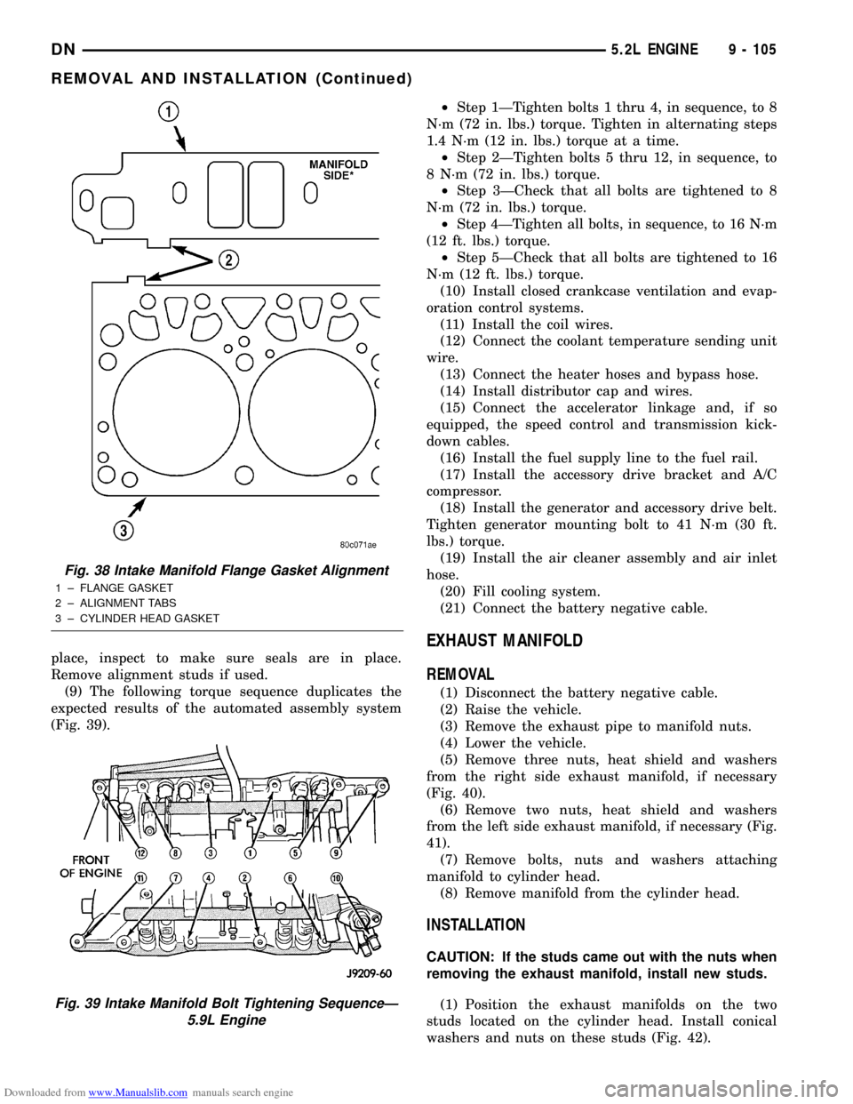
(9) The following torque sequence duplicates the
expected results of the automated assembly system
(Fig. 39).²Step 1ÐTighten bolts 1 thru 4, in sequence, to 8
N´m (72 in. lbs.) torque. Tighten in alternating steps
1.4 N´m (12 in. lbs.) torque at a time.
²Step 2ÐTighten bolts 5 thru 12, in sequence, to
8 N´m (72 in. lbs.) torque.
²Step 3ÐCheck that all bolts are tightened to 8
N´m (72 in. lbs.) torque.
²Step 4ÐTighten all bolts, in sequence, to 16 N´m
(12 ft. lbs.) torque.
²Step 5ÐCheck that all bolts are tightened to 16
N´m (12 ft. lbs.) torque.
(10) Install closed crankcase ventilation and evap-
oration control systems.
(11) Install the coil wires.
(12) Connect the coolant temperature sending unit
wire.
(13) Connect the heater hoses and bypass hose.
(14) Install distributor cap and wires.
(15) Connect the accelerator linkage and, if so
equipped, the speed control and transmission kick-
down cables.
(16) Install the fuel supply line to the fuel rail.
(17) Install the accessory drive bracket and A/C
compressor.
(18) Install the generator and accessory drive belt.
Tighten generator mounting bolt to 41 N´m (30 ft.
lbs.) torque.
(19) Install the air cleaner assembly and air inlet
hose.
(20) Fill cooling system.
(21) Connect the battery negative cable.
EXHAUST MANIFOLD
REMOVAL
(1) Disconnect the battery negative cable.
(2) Raise the vehicle.
(3) Remove the exhaust pipe to manifold nuts.
(4) Lower the vehicle.
(5) Remove three nuts, heat shield and washers
from the right side exhaust manifold, if necessary
(Fig. 40).
(6) Remove two nuts, heat shield and washers
from the left side exhaust manifold, if necessary (Fig.
41).
(7) Remove bolts, nuts and washers attaching
manifold to cylinder head.
(8) Remove manifold from the cylinder head.
INSTALLATION
CAUTION: If the studs came out with the nuts when
removing the exhaust manifold, install new studs.
(1) Position the exhaust manifolds on the two
studs located on the cylinder head. Install conical
washers and nuts on these studs (Fig. 42).
Fig. 38 Intake Manifold Flange Gasket Alignment
1 ± FLANGE GASKET
2 ± ALIGNMENT TABS
3 ± CYLINDER HEAD GASKET
Fig. 39 Intake Manifold Bolt Tightening SequenceÐ
5.9L Engine
DN5.2L ENGINE 9 - 105
REMOVAL AND INSTALLATION (Continued)