ESP DODGE DURANGO 1998 1.G User Guide
[x] Cancel search | Manufacturer: DODGE, Model Year: 1998, Model line: DURANGO, Model: DODGE DURANGO 1998 1.GPages: 193, PDF Size: 5.65 MB
Page 157 of 193

Downloaded from www.Manualslib.com manuals search engine (7) Place timing chain around both sprockets.
(8) Turn crankshaft and camshaft to line up with
keyway location in crankshaft sprocket and in cam-
shaft sprocket.
(9) Lift sprockets and chain (keep sprockets tight
against the chain in position as described).
(10) Slide both sprockets evenly over their respec-
tive shafts and use a straightedge to check alignment
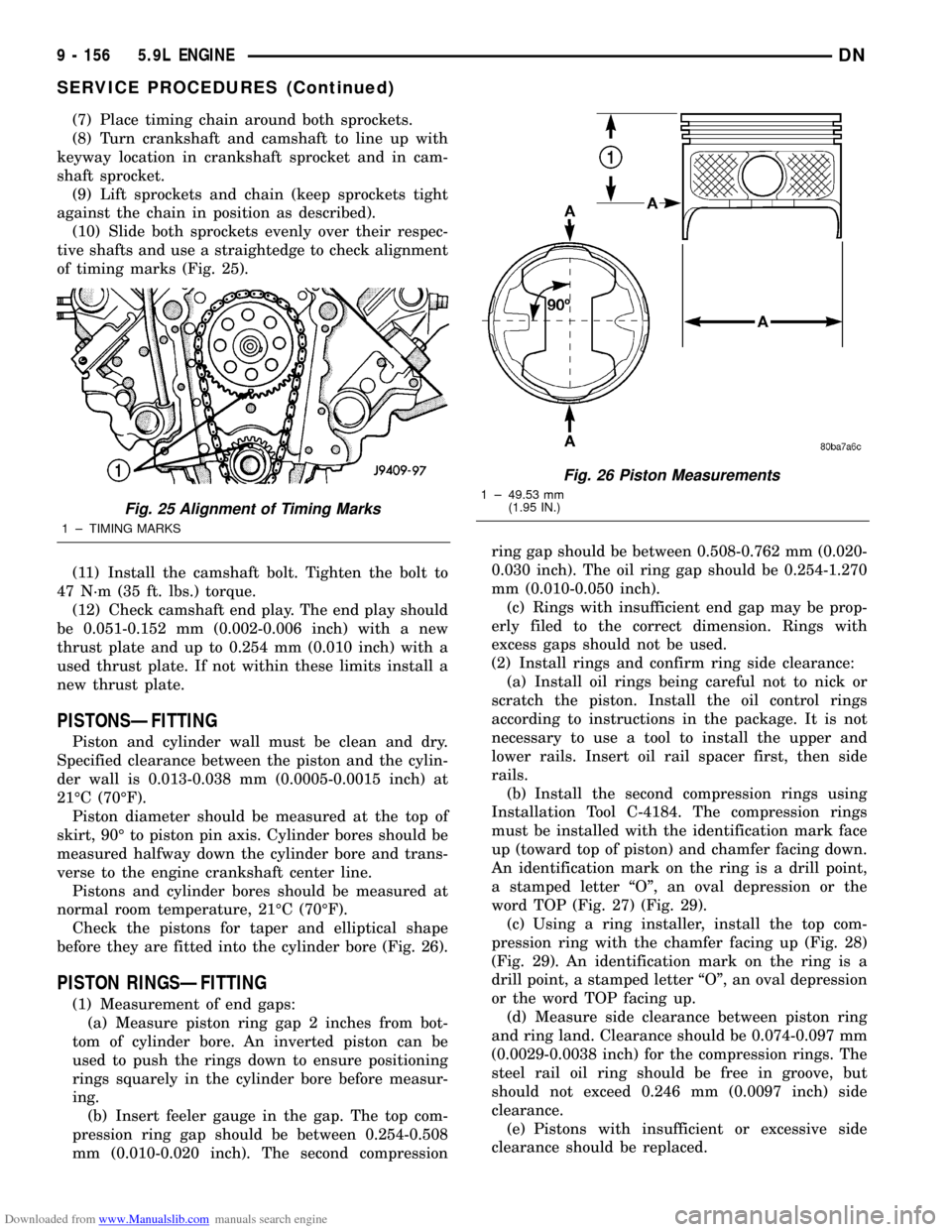
of timing marks (Fig. 25).
(11) Install the camshaft bolt. Tighten the bolt to
47 N´m (35 ft. lbs.) torque.
(12) Check camshaft end play. The end play should
be 0.051-0.152 mm (0.002-0.006 inch) with a new
thrust plate and up to 0.254 mm (0.010 inch) with a
used thrust plate. If not within these limits install a
new thrust plate.
PISTONSÐFITTING
Piston and cylinder wall must be clean and dry.
Specified clearance between the piston and the cylin-
der wall is 0.013-0.038 mm (0.0005-0.0015 inch) at
21ÉC (70ÉF).
Piston diameter should be measured at the top of
skirt, 90É to piston pin axis. Cylinder bores should be
measured halfway down the cylinder bore and trans-
verse to the engine crankshaft center line.
Pistons and cylinder bores should be measured at
normal room temperature, 21ÉC (70ÉF).
Check the pistons for taper and elliptical shape
before they are fitted into the cylinder bore (Fig. 26).
PISTON RINGSÐFITTING
(1) Measurement of end gaps:
(a) Measure piston ring gap 2 inches from bot-
tom of cylinder bore. An inverted piston can be
used to push the rings down to ensure positioning
rings squarely in the cylinder bore before measur-
ing.
(b) Insert feeler gauge in the gap. The top com-
pression ring gap should be between 0.254-0.508
mm (0.010-0.020 inch). The second compressionring gap should be between 0.508-0.762 mm (0.020-
0.030 inch). The oil ring gap should be 0.254-1.270
mm (0.010-0.050 inch).
(c) Rings with insufficient end gap may be prop-
erly filed to the correct dimension. Rings with
excess gaps should not be used.
(2) Install rings and confirm ring side clearance:
(a) Install oil rings being careful not to nick or
scratch the piston. Install the oil control rings
according to instructions in the package. It is not
necessary to use a tool to install the upper and
lower rails. Insert oil rail spacer first, then side
rails.
(b) Install the second compression rings using
Installation Tool C-4184. The compression rings
must be installed with the identification mark face
up (toward top of piston) and chamfer facing down.
An identification mark on the ring is a drill point,
a stamped letter ªOº, an oval depression or the
word TOP (Fig. 27) (Fig. 29).
(c) Using a ring installer, install the top com-
pression ring with the chamfer facing up (Fig. 28)
(Fig. 29). An identification mark on the ring is a
drill point, a stamped letter ªOº, an oval depression
or the word TOP facing up.
(d) Measure side clearance between piston ring
and ring land. Clearance should be 0.074-0.097 mm
(0.0029-0.0038 inch) for the compression rings. The
steel rail oil ring should be free in groove, but
should not exceed 0.246 mm (0.0097 inch) side
clearance.
(e) Pistons with insufficient or excessive side
clearance should be replaced.
Fig. 25 Alignment of Timing Marks
1 ± TIMING MARKS
Fig. 26 Piston Measurements
1 ± 49.53 mm
(1.95 IN.)
9 - 156 5.9L ENGINEDN
SERVICE PROCEDURES (Continued)
Page 171 of 193

Downloaded from www.Manualslib.com manuals search engine (10) Remove the vibration damper bolt and seal
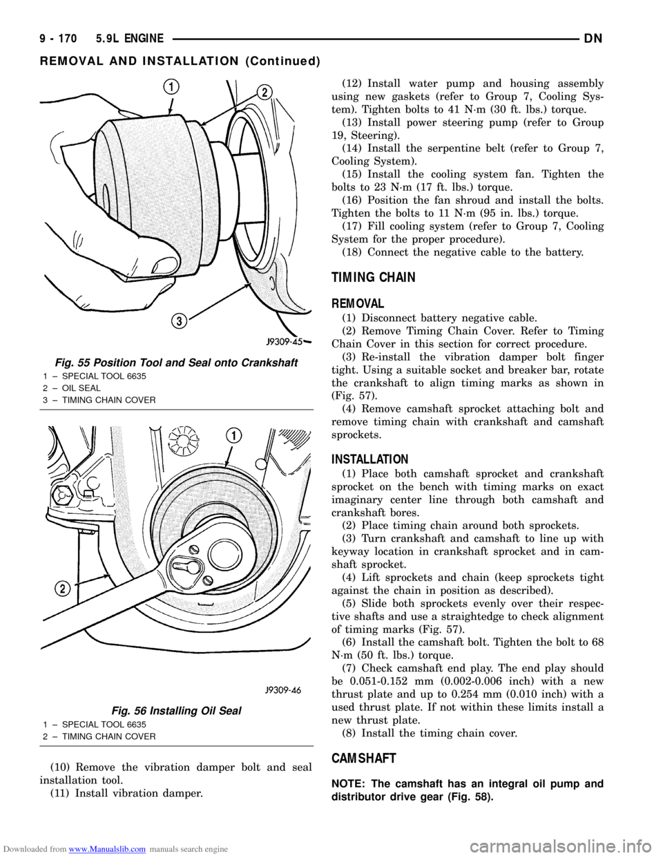
installation tool.
(11) Install vibration damper.(12) Install water pump and housing assembly
using new gaskets (refer to Group 7, Cooling Sys-
tem). Tighten bolts to 41 N´m (30 ft. lbs.) torque.
(13) Install power steering pump (refer to Group
19, Steering).
(14) Install the serpentine belt (refer to Group 7,
Cooling System).
(15) Install the cooling system fan. Tighten the
bolts to 23 N´m (17 ft. lbs.) torque.
(16) Position the fan shroud and install the bolts.
Tighten the bolts to 11 N´m (95 in. lbs.) torque.
(17) Fill cooling system (refer to Group 7, Cooling
System for the proper procedure).
(18) Connect the negative cable to the battery.
TIMING CHAIN
REMOVAL
(1) Disconnect battery negative cable.
(2) Remove Timing Chain Cover. Refer to Timing
Chain Cover in this section for correct procedure.
(3) Re-install the vibration damper bolt finger
tight. Using a suitable socket and breaker bar, rotate
the crankshaft to align timing marks as shown in
(Fig. 57).
(4) Remove camshaft sprocket attaching bolt and
remove timing chain with crankshaft and camshaft
sprockets.
INSTALLATION
(1) Place both camshaft sprocket and crankshaft
sprocket on the bench with timing marks on exact
imaginary center line through both camshaft and
crankshaft bores.
(2) Place timing chain around both sprockets.
(3) Turn crankshaft and camshaft to line up with
keyway location in crankshaft sprocket and in cam-
shaft sprocket.
(4) Lift sprockets and chain (keep sprockets tight
against the chain in position as described).
(5) Slide both sprockets evenly over their respec-
tive shafts and use a straightedge to check alignment
of timing marks (Fig. 57).
(6) Install the camshaft bolt. Tighten the bolt to 68
N´m (50 ft. lbs.) torque.
(7) Check camshaft end play. The end play should
be 0.051-0.152 mm (0.002-0.006 inch) with a new
thrust plate and up to 0.254 mm (0.010 inch) with a
used thrust plate. If not within these limits install a
new thrust plate.
(8) Install the timing chain cover.
CAMSHAFT
NOTE: The camshaft has an integral oil pump and
distributor drive gear (Fig. 58).
Fig. 55 Position Tool and Seal onto Crankshaft
1 ± SPECIAL TOOL 6635
2 ± OIL SEAL
3 ± TIMING CHAIN COVER
Fig. 56 Installing Oil Seal
1 ± SPECIAL TOOL 6635
2 ± TIMING CHAIN COVER
9 - 170 5.9L ENGINEDN
REMOVAL AND INSTALLATION (Continued)
Page 173 of 193

Downloaded from www.Manualslib.com manuals search engine torque. Top edge of tab should be flat against thrust
plate in order to catch oil for chain lubrication.
(5) Place both camshaft sprocket and crankshaft
sprocket on the bench with timing marks on exact
imaginary center line through both camshaft and
crankshaft bores.
(6) Place timing chain around both sprockets.
(7) Turn crankshaft and camshaft to line up with
keyway location in crankshaft sprocket and in cam-
shaft sprocket.
(8) Lift sprockets and chain (keep sprockets tight
against the chain in position as described).
(9) Slide both sprockets evenly over their respec-
tive shafts and use a straightedge to check alignment
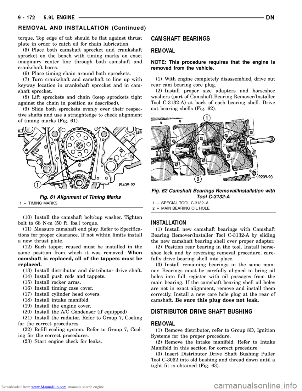
of timing marks (Fig. 61).
(10) Install the camshaft bolt/cup washer. Tighten
bolt to 68 N´m (50 ft. lbs.) torque.
(11) Measure camshaft end play. Refer to Specifica-
tions for proper clearance. If not within limits install
a new thrust plate.
(12) Each tappet reused must be installed in the
same position from which it was removed.When
camshaft is replaced, all of the tappets must be
replaced.
(13) Install distributor and distributor drive shaft.
(14) Install push rods and tappets.
(15) Install rocker arms.
(16) Install timing case cover.
(17) Install cylinder head covers.
(18) Install intake manifold.
(19) Install the engine cover.
(20) Install the A/C Condenser (if equipped)
(21) Install the radiator. Refer to Group 7, Cooling
for the correct procedures.
(22) Refill cooling system. Refer to Group 7, Cool-
ing for the correct procedures.
(23) Start engine check for leaks.CAMSHAFT BEARINGS
REMOVAL
NOTE: This procedure requires that the engine is
removed from the vehicle.
(1) With engine completely disassembled, drive out
rear cam bearing core plug.
(2) Install proper size adapters and horseshoe
washers (part of Camshaft Bearing Remover/Installer
Tool C-3132-A) at back of each bearing shell. Drive
out bearing shells (Fig. 62).
INSTALLATION
(1) Install new camshaft bearings with Camshaft
Bearing Remover/Installer Tool C-3132-A by sliding
the new camshaft bearing shell over proper adapter.
(2) Position rear bearing in the tool. Install horse-
shoe lock and by reversing removal procedure, care-
fully drive bearing shell into place.
(3) Install remaining bearings in the same man-
ner. Bearings must be carefully aligned to bring oil
holes into full register with oil passages from the
main bearing. If the camshaft bearing shell oil holes
are not in exact alignment, remove and install them
correctly. Install a new core hole plug at the rear of
camshaft.Be sure this plug does not leak.
DISTRIBUTOR DRIVE SHAFT BUSHING
REMOVAL
(1) Remove distributor, refer to Group 8D, Ignition
Systems for the proper procedure.
(2) Remove the intake manifold. Refer to Intake
Manifold in this section for correct procedure.
(3) Insert Distributor Drive Shaft Bushing Puller
Tool C-3052 into old bushing and thread down until a
tight fit is obtained (Fig. 63).
Fig. 61 Alignment of Timing Marks
1 ± TIMING MARKS
Fig. 62 Camshaft Bearings Removal/Installation with
Tool C-3132-A
1 ± SPECIAL TOOL C-3132±A
2 ± MAIN BEARING OIL HOLE
9 - 172 5.9L ENGINEDN
REMOVAL AND INSTALLATION (Continued)