ESP DODGE DURANGO 1998 1.G Workshop Manual
[x] Cancel search | Manufacturer: DODGE, Model Year: 1998, Model line: DURANGO, Model: DODGE DURANGO 1998 1.GPages: 193, PDF Size: 5.65 MB
Page 14 of 193
Downloaded from www.Manualslib.com manuals search engine filter runoff, and main bearing cap to cylinder
block mating surfaces.
(4) If no leaks are detected, pressurize the crank-
case as outlined in the, Inspection (Engine oil Leaks
in general)
CAUTION: Do not exceed 20.6 kPa (3 psi).
(5) If the leak is not detected, very slowly turn the
crankshaft and watch for leakage. If a leak is
detected between the crankshaft and seal while
slowly turning the crankshaft, it is possible the
crankshaft seal surface is damaged. The seal area on
the crankshaft could have minor nicks or scratches
that can be polished out with emery cloth.
CAUTION: Use extreme caution when crankshaft
polishing is necessary to remove minor nicks and
scratches. The crankshaft seal flange is especially
machined to complement the function of the rear oil
seal.
(6) For bubbles that remain steady with shaft
rotation, no further inspection can be done until dis-
assembled.
REAR SEAL AREA LEAKSÐINSPECTION
Since it is sometimes difficult to determine the
source of an oil leak in the rear seal area of the
engine, a more involved inspection is necessary. The
following steps should be followed to help pinpoint
the source of the leak.
If the leakage occurs at the crankshaft rear oil seal
area:
(1) Disconnect the battery.
(2) Raise the vehicle.
(3) Remove torque converter or clutch housing
cover and inspect rear of block for evidence of oil.
Use a black light to check for the oil leak:
(a) Circular spray pattern generally indicates
seal leakage or crankshaft damage.
(b) Where leakage tends to run straight down,
possible causes are a porous block, distributor seal,
camshaft bore cup plugs, oil galley pipe plugs, oil
filter runoff, and main bearing cap to cylinder
block mating surfaces. See Group 9, Engines, for
proper repair procedures of these items.
(4) If no leaks are detected, pressurized the crank-
case as outlined in the section, Inspection (Engine oil
Leaks in general)
CAUTION: Do not exceed 20.6 kPa (3 psi).
(5) If the leak is not detected, very slowly turn the
crankshaft and watch for leakage. If a leak is
detected between the crankshaft and seal while
slowly turning the crankshaft, it is possible thecrankshaft seal surface is damaged. The seal area on
the crankshaft could have minor nicks or scratches
that can be polished out with emery cloth.
CAUTION: Use extreme caution when crankshaft
polishing is necessary to remove minor nicks or
scratches. The crankshaft seal flange is specially
machined to complement the function of the rear oil
seal.
(6) For bubbles that remain steady with shaft
rotation, no further inspection can be done until dis-
assembled. Refer to the service DiagnosisÐMechani-
cal, under the Oil Leak row, for components
inspections on possible causes and corrections.
(7) After the oil leak root cause and appropriate
corrective action have been identified, Refer to Group
9, EnginesÐCrankshaft Rear Oil Seals, for proper
replacement procedures.
HYDRAULIC LASH ADJUSTER NOISE
DIAGNOSIS
A tappet-like noise may be produced from several
items. Check the following items.
(1) Engine oil level too high or too low. This may
cause aerated oil to enter the adjusters and cause
them to be spongy.
(2) Insufficient running time after rebuilding cylin-
der head. Low speed running up to 1 hour may be
required.
(3) Turn engine off and let set for a few minutes
before restarting. Repeat this several times after
engine has reached normal operating temperature.
(4) Low oil pressure.
(5) The oil restrictor in cylinder head gasket or the
oil passage to the cylinder head is plugged with
debris.
(6) Air ingested into oil due to broken or cracked
oil pump pick up.
(7) Worn valve guides.
(8) Rocker arm ears contacting valve spring
retainer.
(9) Rocker arm loose, adjuster stuck or at maxi-
mum extension and still leaves lash in the system.
(10) Faulty lash adjuster.
a. Check lash adjusters for sponginess while
installed in cylinder head and cam on camshaft at
base circle. Depress part of rocker arm over adjuster.
Normal adjusters should feel very firm. Spongy
adjusters can be bottomed out easily.
b. Remove suspected lash adjusters, and replace.
c. Before installation, make sure adjusters are at
least partially full of oil. This can be verified by little
or no plunger travel when lash adjuster is depressed.
9 - 14 4.7L ENGINEDN
DIAGNOSIS AND TESTING (Continued)
Page 34 of 193
Downloaded from www.Manualslib.com manuals search engine (20) Install both breathers. Connect tube to both
crankcase breathers (Fig. 44).
(21) Connect throttle and speed control cables.
(22) Install throttle body resonator assembly and
air inlet hose. Tighten clamps 4 N´m (35 in. lbs.).
(23) Raise vehicle.
(24) Install transmission to engine mounting bolts.
Tighten the bolts to 41 N´m (30 ft. lbs.).
(25) Install torque converter bolts (Automatic
Transmission Only).
(26) Connect crankshaft position sensor (Fig. 43).
(27)4X4 vehiclesPosition and install the axle
isolator bracket onto the axle, transmission and
engine block. Tighten bolts to specification. Refer to
Specifications in this section.
(28) Install starter.
CAUTION: The structural cover requires a specific
torque sequence. Failure to follow this sequence
may cause severe damage to the cover.(29) Install structural cover. Refer to Structural
Cover in this section.
(30) Install exhaust crossover pipe.
(31) Install engine block heater power cable, If
equipped.
(32)4X4 vehiclesConnect axle vent tube to left
side engine mount.
(33) Lower vehicle.
(34) Check and fill engine oil.
(35) Recharge the A/C system.
(36) Refill the engine cooling system. Refer to
COOLING SYSTEM.
(37) Install the battery tray and battery.
(38) Connect the battery positive and negative
cables.
(39) Start the engine and check for leaks.
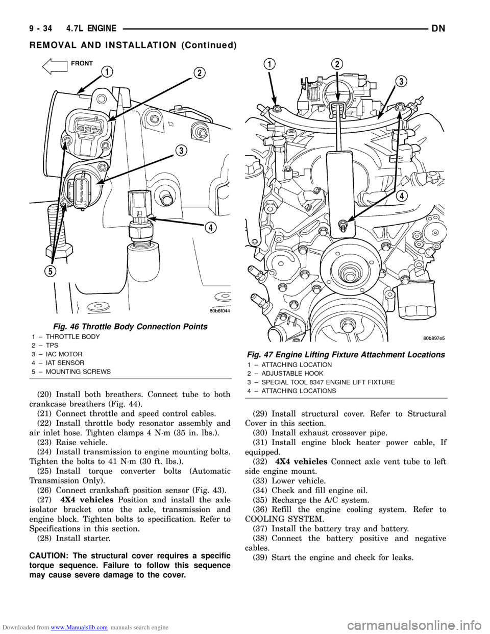
Fig. 46 Throttle Body Connection Points
1 ± THROTTLE BODY
2 ± TPS
3 ± IAC MOTOR
4 ± IAT SENSOR
5 ± MOUNTING SCREWS
Fig. 47 Engine Lifting Fixture Attachment Locations
1 ± ATTACHING LOCATION
2 ± ADJUSTABLE HOOK
3 ± SPECIAL TOOL 8347 ENGINE LIFT FIXTURE
4 ± ATTACHING LOCATIONS
9 - 34 4.7L ENGINEDN
REMOVAL AND INSTALLATION (Continued)
Page 61 of 193
Downloaded from www.Manualslib.com manuals search engine INSTALLATION
(1) Lubricate camshaft journals with clean engine
oil.
NOTE: Position the right side camshaft so that the
camshaft sprocket dowel is near the 10 o'clock
position, This will place the camshaft at the neutral
position easing the installation of the camshaft
bearing caps.
(2) Position the camshaft into the cylinder head.
(3) Install the camshaft bearing caps, hand tighten
the retaining bolts.
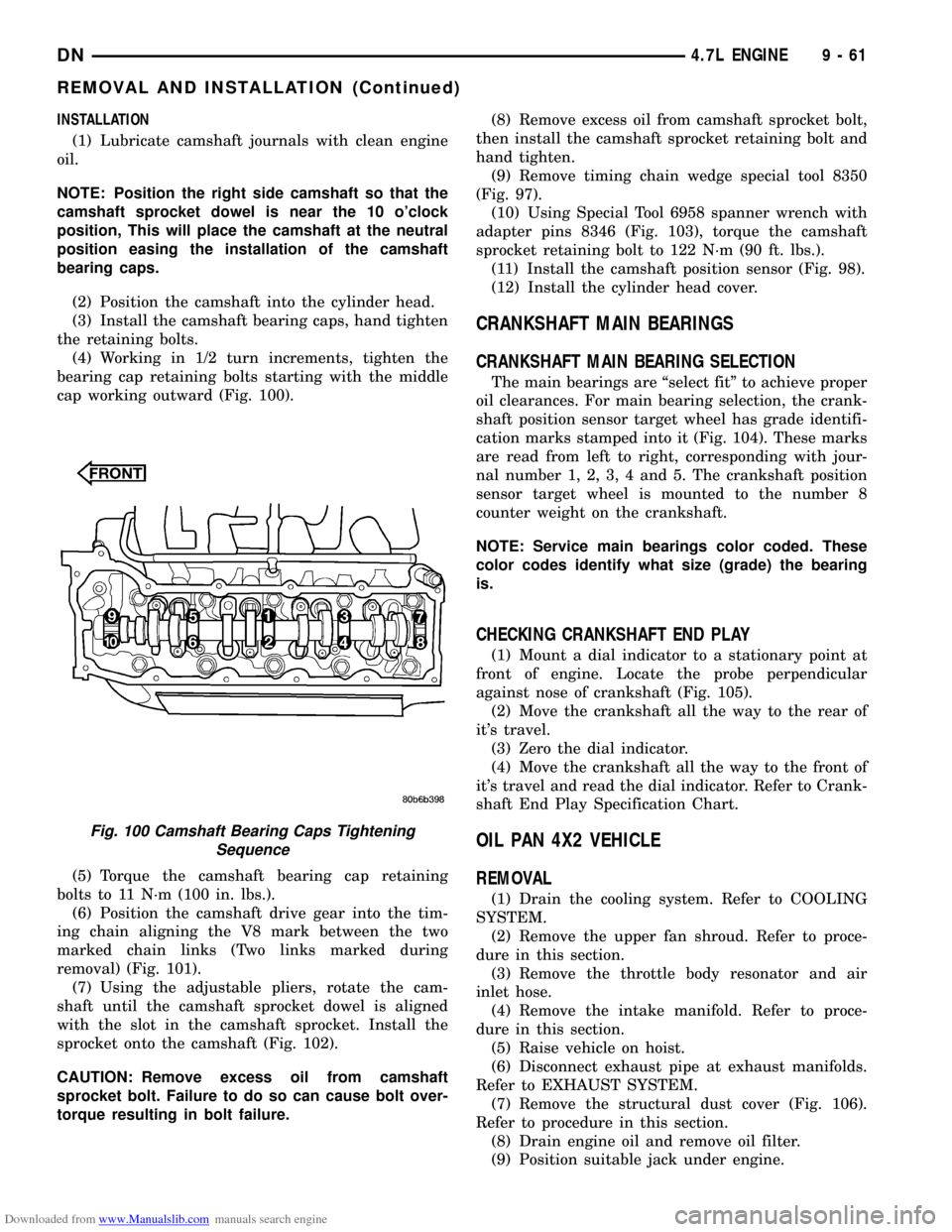
(4) Working in 1/2 turn increments, tighten the
bearing cap retaining bolts starting with the middle
cap working outward (Fig. 100).
(5) Torque the camshaft bearing cap retaining
bolts to 11 N´m (100 in. lbs.).
(6) Position the camshaft drive gear into the tim-
ing chain aligning the V8 mark between the two
marked chain links (Two links marked during
removal) (Fig. 101).
(7) Using the adjustable pliers, rotate the cam-
shaft until the camshaft sprocket dowel is aligned
with the slot in the camshaft sprocket. Install the
sprocket onto the camshaft (Fig. 102).
CAUTION: Remove excess oil from camshaft
sprocket bolt. Failure to do so can cause bolt over-
torque resulting in bolt failure.(8) Remove excess oil from camshaft sprocket bolt,
then install the camshaft sprocket retaining bolt and
hand tighten.
(9) Remove timing chain wedge special tool 8350
(Fig. 97).
(10) Using Special Tool 6958 spanner wrench with
adapter pins 8346 (Fig. 103), torque the camshaft
sprocket retaining bolt to 122 N´m (90 ft. lbs.).
(11) Install the camshaft position sensor (Fig. 98).
(12) Install the cylinder head cover.
CRANKSHAFT MAIN BEARINGS
CRANKSHAFT MAIN BEARING SELECTION
The main bearings are ªselect fitº to achieve proper
oil clearances. For main bearing selection, the crank-
shaft position sensor target wheel has grade identifi-
cation marks stamped into it (Fig. 104). These marks
are read from left to right, corresponding with jour-
nal number 1, 2, 3, 4 and 5. The crankshaft position
sensor target wheel is mounted to the number 8
counter weight on the crankshaft.
NOTE: Service main bearings color coded. These
color codes identify what size (grade) the bearing
is.
CHECKING CRANKSHAFT END PLAY
(1) Mount a dial indicator to a stationary point at
front of engine. Locate the probe perpendicular
against nose of crankshaft (Fig. 105).
(2) Move the crankshaft all the way to the rear of
it's travel.
(3) Zero the dial indicator.
(4) Move the crankshaft all the way to the front of
it's travel and read the dial indicator. Refer to Crank-
shaft End Play Specification Chart.
OIL PAN 4X2 VEHICLE
REMOVAL
(1) Drain the cooling system. Refer to COOLING
SYSTEM.
(2) Remove the upper fan shroud. Refer to proce-
dure in this section.
(3) Remove the throttle body resonator and air
inlet hose.
(4) Remove the intake manifold. Refer to proce-
dure in this section.
(5) Raise vehicle on hoist.
(6) Disconnect exhaust pipe at exhaust manifolds.
Refer to EXHAUST SYSTEM.
(7) Remove the structural dust cover (Fig. 106).
Refer to procedure in this section.
(8) Drain engine oil and remove oil filter.
(9) Position suitable jack under engine.
Fig. 100 Camshaft Bearing Caps Tightening
Sequence
DN4.7L ENGINE 9 - 61
REMOVAL AND INSTALLATION (Continued)
Page 75 of 193
Downloaded from www.Manualslib.com manuals search engine NOTE: Once the oil pressure relief valve, cup plug,
and pin are removed, the pump assembly must be
replaced.
(3) If it is necessary to remove the pressure relief
valve, drive the roll pin from pump housing and
remove cup plug, spring and valve.
ASSEMBLE
(1) Wash all parts in a suitable solvent and inspect
carefully for damage or wear.
(2) Install inner and outer rotors
(3) Install oil pump cover plate and install cover
bolts and tighten them to 12 N´m (105 in. lbs.).
(4) Prime oil pump before installation by filling
rotor cavity with engine oil.
(5) If oil pressure is low and pump is within spec-
ifications, inspect for worn engine bearings or other
causes for oil pressure loss.
CLEANING AND INSPECTION
INTAKE MANIFOLD
CLEANING
NOTE: There is NO approved repair procedure for
the intake manifold. If severe damage is found dur-
ing inspection, the intake manifold must be
replaced.
Before installing the intake manifold thoroughly
clean the mating surfaces. Use a suitable cleaning
solvent, then air dry.
INSPECTION
(1) Inspect the intake sealing surface for cracks,
nicks and distortion.
(2) Inspect the intake manifold vacuum hose fit-
tings for looseness or blockage.
(3) Inspect the manifold to throttle body mating
surface for cracks, nicks and distortion.
EXHAUST MANIFOLD
CLEANING
(1) Clean the exhaust manifold using a suitable
cleaning solvent, then allow to air dry.
(2) Clean all gasket residue from the manifold
mating surface.
INSPECTION
(1) Inspect the exhaust manifold for cracks in the
mating surface and at every mounting bolt hole.
(2) Using a straight edge and a feeler gauge, check
the mating surface for warp and twist.(3) Inspect the manifold to exhaust pipe mating
surface for cracks, gouges, or other damage that
would prevent sealing.
CYLINDER HEADS
CLEANING
CYLINDER HEAD GASKET SURFACE PREPARATION
To ensure engine gasket sealing, proper surface
preparation must be performed, especially with the
use of aluminum engine components.
Never use the following to clean gasket surfaces:
²never use a metal scraper.
²never use an abrasive pad or paper to
clean the cylinder block.
²never use a high speed power tool or wire
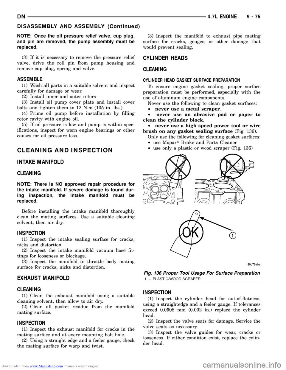
brush on any gasket sealing surface(Fig. 136).
Only use the following for cleaning gasket surfaces:
²use MopartBrake and Parts Cleaner
²use only a plastic or wood scraper (Fig. 136)
INSPECTION
(1) Inspect the cylinder head for out-of-flatness,
using a straightedge and a feeler gauge. If tolerances
exceed 0.0508 mm (0.002 in.) replace the cylinder
head.
(2) Inspect the valve seats for damage. Service the
valve seats as necessary.
(3) Inspect the valve guides for wear, cracks or
looseness. If either condition exist, replace the cylin-
der head.
Fig. 136 Proper Tool Usage For Surface Preparation
1 ± PLASTIC/WOOD SCRAPER
DN4.7L ENGINE 9 - 75
DISASSEMBLY AND ASSEMBLY (Continued)
Page 87 of 193
Downloaded from www.Manualslib.com manuals search engine ENGINE LUBRICATION SYSTEM
DESCRIPTION
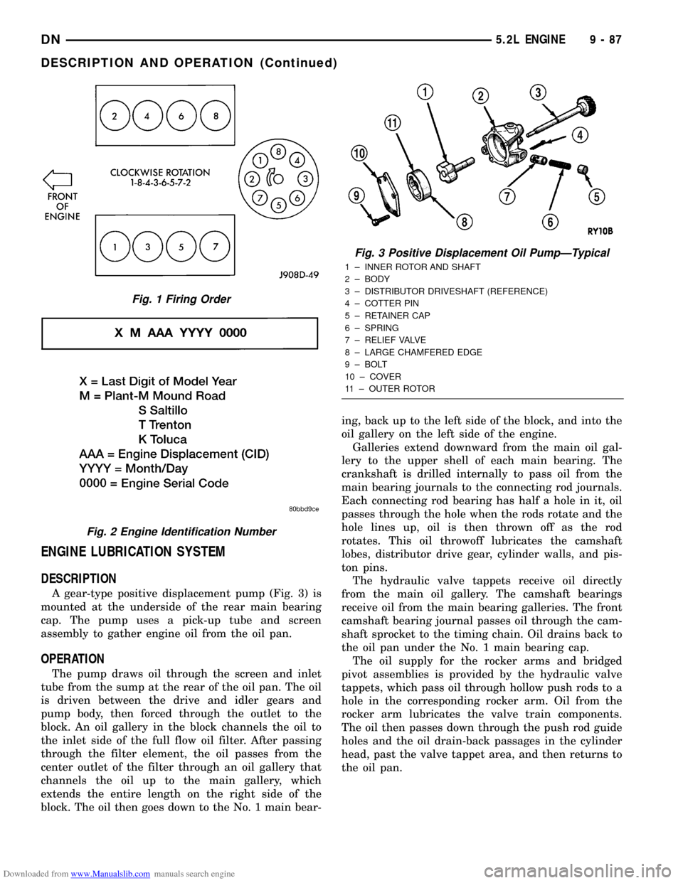
A gear-type positive displacement pump (Fig. 3) is
mounted at the underside of the rear main bearing
cap. The pump uses a pick-up tube and screen
assembly to gather engine oil from the oil pan.
OPERATION
The pump draws oil through the screen and inlet
tube from the sump at the rear of the oil pan. The oil
is driven between the drive and idler gears and
pump body, then forced through the outlet to the
block. An oil gallery in the block channels the oil to
the inlet side of the full flow oil filter. After passing
through the filter element, the oil passes from the
center outlet of the filter through an oil gallery that
channels the oil up to the main gallery, which
extends the entire length on the right side of the
block. The oil then goes down to the No. 1 main bear-ing, back up to the left side of the block, and into the
oil gallery on the left side of the engine.
Galleries extend downward from the main oil gal-
lery to the upper shell of each main bearing. The
crankshaft is drilled internally to pass oil from the
main bearing journals to the connecting rod journals.
Each connecting rod bearing has half a hole in it, oil
passes through the hole when the rods rotate and the
hole lines up, oil is then thrown off as the rod
rotates. This oil throwoff lubricates the camshaft
lobes, distributor drive gear, cylinder walls, and pis-
ton pins.
The hydraulic valve tappets receive oil directly
from the main oil gallery. The camshaft bearings
receive oil from the main bearing galleries. The front
camshaft bearing journal passes oil through the cam-
shaft sprocket to the timing chain. Oil drains back to
the oil pan under the No. 1 main bearing cap.
The oil supply for the rocker arms and bridged
pivot assemblies is provided by the hydraulic valve
tappets, which pass oil through hollow push rods to a
hole in the corresponding rocker arm. Oil from the
rocker arm lubricates the valve train components.
The oil then passes down through the push rod guide
holes and the oil drain-back passages in the cylinder
head, past the valve tappet area, and then returns to
the oil pan.
Fig. 1 Firing Order
Fig. 2 Engine Identification Number
Fig. 3 Positive Displacement Oil PumpÐTypical
1 ± INNER ROTOR AND SHAFT
2 ± BODY
3 ± DISTRIBUTOR DRIVESHAFT (REFERENCE)
4 ± COTTER PIN
5 ± RETAINER CAP
6 ± SPRING
7 ± RELIEF VALVE
8 ± LARGE CHAMFERED EDGE
9 ± BOLT
10 ± COVER
11 ± OUTER ROTOR
DN5.2L ENGINE 9 - 87
DESCRIPTION AND OPERATION (Continued)
Page 98 of 193
Downloaded from www.Manualslib.com manuals search engine sprocket bolt, crankshaft should not be permitted to
move. It may be necessary to block the crankshaft to
prevent rotation.
(3) Hold a scale with dimensional reading even
with the edge of a chain link. With cylinder heads
installed, apply 14 N´m (30 ft. lbs.) torque in the
reverse direction. With the cylinder heads removed,
apply 20 N´m (15 ft. lbs.) torque in the reverse direc-
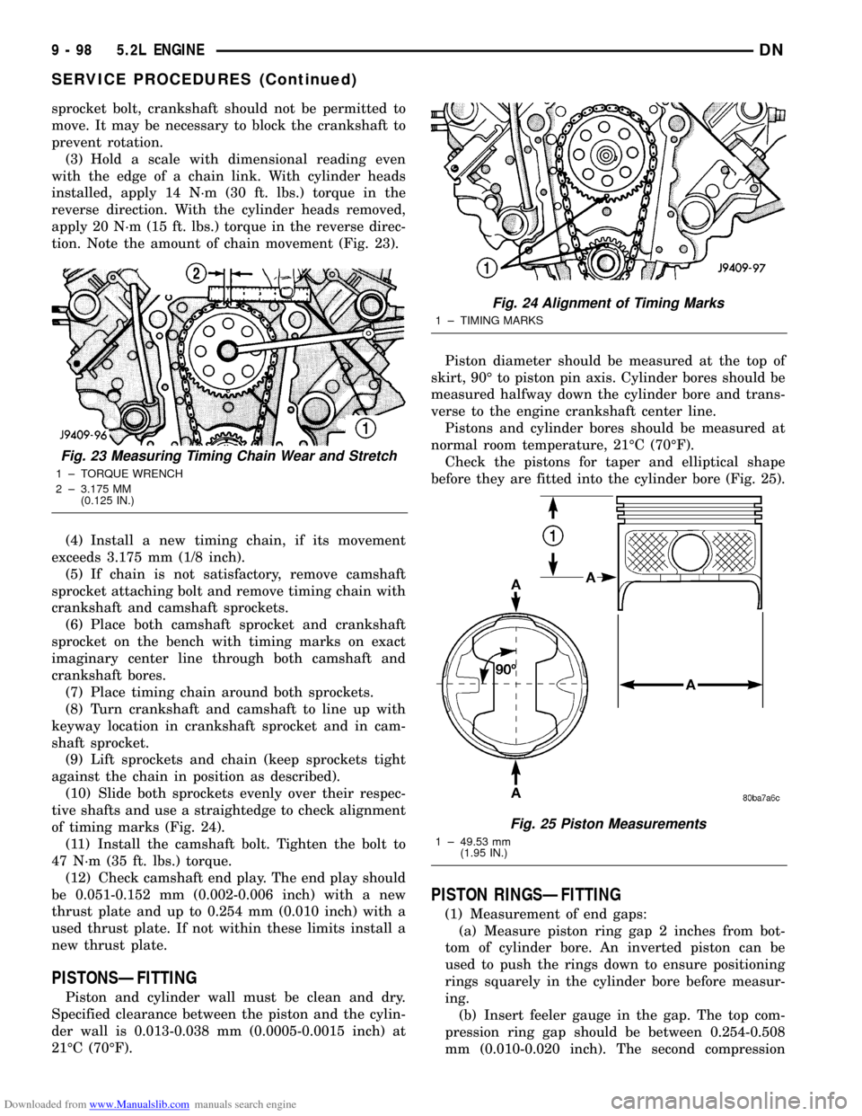
tion. Note the amount of chain movement (Fig. 23).
(4) Install a new timing chain, if its movement
exceeds 3.175 mm (1/8 inch).
(5) If chain is not satisfactory, remove camshaft
sprocket attaching bolt and remove timing chain with
crankshaft and camshaft sprockets.
(6) Place both camshaft sprocket and crankshaft
sprocket on the bench with timing marks on exact
imaginary center line through both camshaft and
crankshaft bores.
(7) Place timing chain around both sprockets.
(8) Turn crankshaft and camshaft to line up with
keyway location in crankshaft sprocket and in cam-
shaft sprocket.
(9) Lift sprockets and chain (keep sprockets tight
against the chain in position as described).
(10) Slide both sprockets evenly over their respec-
tive shafts and use a straightedge to check alignment
of timing marks (Fig. 24).
(11) Install the camshaft bolt. Tighten the bolt to
47 N´m (35 ft. lbs.) torque.
(12) Check camshaft end play. The end play should
be 0.051-0.152 mm (0.002-0.006 inch) with a new
thrust plate and up to 0.254 mm (0.010 inch) with a
used thrust plate. If not within these limits install a
new thrust plate.
PISTONSÐFITTING
Piston and cylinder wall must be clean and dry.
Specified clearance between the piston and the cylin-
der wall is 0.013-0.038 mm (0.0005-0.0015 inch) at
21ÉC (70ÉF).Piston diameter should be measured at the top of
skirt, 90É to piston pin axis. Cylinder bores should be
measured halfway down the cylinder bore and trans-
verse to the engine crankshaft center line.
Pistons and cylinder bores should be measured at
normal room temperature, 21ÉC (70ÉF).
Check the pistons for taper and elliptical shape
before they are fitted into the cylinder bore (Fig. 25).
PISTON RINGSÐFITTING
(1) Measurement of end gaps:
(a) Measure piston ring gap 2 inches from bot-
tom of cylinder bore. An inverted piston can be
used to push the rings down to ensure positioning
rings squarely in the cylinder bore before measur-
ing.
(b) Insert feeler gauge in the gap. The top com-
pression ring gap should be between 0.254-0.508
mm (0.010-0.020 inch). The second compression
Fig. 23 Measuring Timing Chain Wear and Stretch
1 ± TORQUE WRENCH
2 ± 3.175 MM
(0.125 IN.)
Fig. 24 Alignment of Timing Marks
1 ± TIMING MARKS
Fig. 25 Piston Measurements
1 ± 49.53 mm
(1.95 IN.)
9 - 98 5.2L ENGINEDN
SERVICE PROCEDURES (Continued)
Page 111 of 193
Downloaded from www.Manualslib.com manuals search engine (9) Tighten chain case cover bolts to 41 N´m (30 ft.
lbs.) torque. Tighten oil pan bolts to 24 N´m (215 in.
lbs.) torque.
(10) Remove the vibration damper bolt and seal
installation tool.
(11) Install vibration damper.
(12) Install water pump and housing assembly
using new gaskets (refer to Group 7, Cooling Sys-
tem). Tighten bolts to 41 N´m (30 ft. lbs.) torque.
(13) Install power steering pump (refer to Group
19, Steering).
(14) Install the serpentine belt (refer to Group 7,
Cooling System).
(15) Install the cooling system fan. Tighten the
bolts to 23 N´m (17 ft. lbs.) torque.
(16) Position the fan shroud and install the bolts.
Tighten the bolts to 11 N´m (95 in. lbs.) torque.
(17) Fill cooling system (refer to Group 7, Cooling
System for the proper procedure).
(18) Connect the negative cable to the battery.
TIMING CHAIN
REMOVAL
(1) Disconnect battery negative cable.
(2) Remove Timing Chain Cover. Refer to Timing
Chain Cover in this section for correct procedure.
(3) Re-install the vibration damper bolt finger
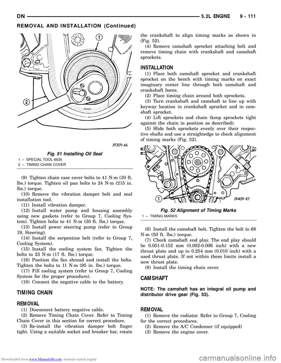
tight. Using a suitable socket and breaker bar, rotatethe crankshaft to align timing marks as shown in
(Fig. 52).
(4) Remove camshaft sprocket attaching bolt and
remove timing chain with crankshaft and camshaft
sprockets.
INSTALLATION
(1) Place both camshaft sprocket and crankshaft
sprocket on the bench with timing marks on exact
imaginary center line through both camshaft and
crankshaft bores.
(2) Place timing chain around both sprockets.
(3) Turn crankshaft and camshaft to line up with
keyway location in crankshaft sprocket and in cam-
shaft sprocket.
(4) Lift sprockets and chain (keep sprockets tight
against the chain in position as described).
(5) Slide both sprockets evenly over their respec-
tive shafts and use a straightedge to check alignment
of timing marks (Fig. 52).
(6) Install the camshaft bolt. Tighten the bolt to 68
N´m (50 ft. lbs.) torque.
(7) Check camshaft end play. The end play should
be 0.051-0.152 mm (0.002-0.006 inch) with a new
thrust plate and up to 0.254 mm (0.010 inch) with a
used thrust plate. If not within these limits install a
new thrust plate.
(8) Install the timing chain cover.
CAMSHAFT
NOTE: The camshaft has an integral oil pump and
distributor drive gear (Fig. 53).
REMOVAL
(1) Remove the radiator. Refer to Group 7, Cooling
for the correct procedures.
(2) Remove the A/C Condenser (if equipped)
(3) Remove the engine cover.
Fig. 51 Installing Oil Seal
1 ± SPECIAL TOOL 6635
2 ± TIMING CHAIN COVER
Fig. 52 Alignment of Timing Marks
1 ± TIMING MARKS
DN5.2L ENGINE 9 - 111
REMOVAL AND INSTALLATION (Continued)
Page 112 of 193
Downloaded from www.Manualslib.com manuals search engine (4) Remove intake manifold. Refer to Intake Man-
ifold in this section for the correct procedure.
(5) Remove cylinder head covers.
(6) Remove timing case cover and timing chain.
(7) Remove rocker arms.
(8) Remove push rods and tappets. Identify each
part so it can be installed in its original location.
(9) Remove distributor and lift out the oil pump
and distributor drive shaft.
(10) Remove camshaft thrust plate, note location of
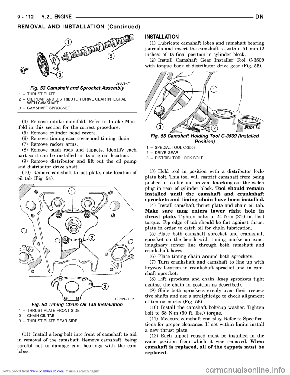
oil tab (Fig. 54).
(11) Install a long bolt into front of camshaft to aid
in removal of the camshaft. Remove camshaft, being
careful not to damage cam bearings with the cam
lobes.
INSTALLATION
(1) Lubricate camshaft lobes and camshaft bearing
journals and insert the camshaft to within 51 mm (2
inches) of its final position in cylinder block.
(2) Install Camshaft Gear Installer Tool C-3509
with tongue back of distributor drive gear (Fig. 55).
(3) Hold tool in position with a distributor lock-
plate bolt. This tool will restrict camshaft from being
pushed in too far and prevent knocking out the welch
plug in rear of cylinder block.Tool should remain
installed until the camshaft and crankshaft
sprockets and timing chain have been installed.
(4) Install camshaft thrust plate and chain oil tab.
Make sure tang enters lower right hole in
thrust plate.Tighten bolts to 24 N´m (210 in. lbs.)
torque. Top edge of tab should be flat against thrust
plate in order to catch oil for chain lubrication.
(5) Place both camshaft sprocket and crankshaft
sprocket on the bench with timing marks on exact
imaginary center line through both camshaft and
crankshaft bores.
(6) Place timing chain around both sprockets.
(7) Turn crankshaft and camshaft to line up with
keyway location in crankshaft sprocket and in cam-
shaft sprocket.
(8) Lift sprockets and chain (keep sprockets tight
against the chain in position as described).
(9) Slide both sprockets evenly over their respec-
tive shafts and use a straightedge to check alignment
of timing marks (Fig. 56).
(10) Install the camshaft bolt/cup washer. Tighten
bolt to 68 N´m (50 ft. lbs.) torque.
(11) Measure camshaft end play. Refer to Specifica-
tions for proper clearance. If not within limits install
a new thrust plate.
(12) Each tappet reused must be installed in the
same position from which it was removed.When
camshaft is replaced, all of the tappets must be
replaced.
Fig. 53 Camshaft and Sprocket Assembly
1 ± THRUST PLATE
2 ± OIL PUMP AND DISTRIBUTOR DRIVE GEAR INTEGRAL
WITH CAMSHAFT
3 ± CAMSHAFT SPROCKET
Fig. 54 Timing Chain Oil Tab Installation
1 ± THRUST PLATE FRONT SIDE
2 ± CHAIN OIL TAB
3 ± THRUST PLATE REAR SIDE
Fig. 55 Camshaft Holding Tool C-3509 (Installed
Position)
1 ± SPECIAL TOOL C-3509
2 ± DRIVE GEAR
3 ± DISTRIBUTOR LOCK BOLT
9 - 112 5.2L ENGINEDN
REMOVAL AND INSTALLATION (Continued)
Page 138 of 193
Downloaded from www.Manualslib.com manuals search engine The hydraulic valve tappets receive oil directly
from the main oil gallery. The camshaft bearings
receive oil from the main bearing galleries. The front
camshaft bearing journal passes oil through the cam-
shaft sprocket to the timing chain. Oil drains back to
the oil pan under the No. 1 main bearing cap.
The oil supply for the rocker arms and bridged
pivot assemblies is provided by the hydraulic valvetappets, which pass oil through hollow push rods to a
hole in the corresponding rocker arm. Oil from the
rocker arm lubricates the valve train components.
The oil then passes down through the push rod guide
holes and the oil drain-back passages in the cylinder
head, past the valve tappet area, and then returns to
the oil pan.
DN5.9L ENGINE 9 - 137
DESCRIPTION AND OPERATION (Continued)
Page 149 of 193
Downloaded from www.Manualslib.com manuals search engine HYDRAULIC TAPPETS
Before disassembling any part of the engine to cor-
rect tappet noise, check the oil pressure. If vehicle
has no oil pressure gauge, install a reliable gauge at
the pressure sending-unit. The pressure should be
between 207-552 kPa (30-80 psi) at 3,000 RPM.
Check the oil level after the engine reaches normal
operating temperature. Allow 5 minutes to stabilize
oil level, check dipstick. The oil level in the pan
should never be above the FULL mark or below the
ADD OIL mark on dipstick. Either of these two con-
ditions could be responsible for noisy tappets.
OIL LEVEL
HIGH
If oil level is above the FULL mark, it is possible
for the connecting rods to dip into the oil. With the
engine running, this condition could create foam in
the oil pan. Foam in oil pan would be fed to the
hydraulic tappets by the oil pump causing them to
lose length and allow valves to seat noisily.
LOW
Low oil level may allow oil pump to take in air.
When air is fed to the tappets, they lose length,
which allows valves to seat noisily. Any leaks on
intake side of oil pump through which air can be
drawn will create the same tappet action. Check the
lubrication system from the intake strainer to the
pump cover, including the relief valve retainer cap.
When tappet noise is due to aeration, it may be
intermittent or constant, and usually more than one
tappet will be noisy. When oil level and leaks have
been corrected, operate the engine at fast idle. Run
engine for a sufficient time to allow all of the air
inside the tappets to be bled out.
TAPPET NOISE DIAGNOSIS
(1) To determine source of tappet noise, operate
engine at idle with cylinder head covers removed.
(2) Feel each valve spring or rocker arm to detect
noisy tappet. The noisy tappet will cause the affected
spring and/or rocker arm to vibrate or feel rough in
operation.
NOTE: Worn valve guides or cocked springs are
sometimes mistaken for noisy tappets. If such is
the case, noise may be dampened by applying side
thrust on the valve spring. If noise is not apprecia-
bly reduced, it can be assumed the noise is in the
tappet. Inspect the rocker arm push rod sockets
and push rod ends for wear.
(3) Valve tappet noise ranges from light noise to a
heavy click. A light noise is usually caused by exces-
sive leak-down around the unit plunger, or by theplunger partially sticking in the tappet body cylinder.
The tappet should be replaced. A heavy click is
caused by a tappet check valve not seating, or by for-
eign particles wedged between the plunger and the
tappet body. This will cause the plunger to stick in
the down position. This heavy click will be accompa-
nied by excessive clearance between the valve stem
and rocker arm as valve closes. In either case, tappet
assembly should be removed for inspection and clean-
ing.
(4) The valve train generates a noise very much
like a light tappet noise during normal operation.
Care must be taken to ensure that tappets are mak-
ing the noise. If more than one tappet seems to be
noisy, it's probably not the tappets.
LEAK-DOWN TEST
After cleaning and inspection, test each tappet for
specified leak-down rate tolerance to ensure zero-lash
operation (Fig. 11).
Swing the weighted arm of the hydraulic valve tap-
pet tester away from the ram of the Universal Leak-
Down Tester.
(1) Place a 7.925-7.950 mm (0.312-0.313 inch)
diameter ball bearing on the plunger cap of the tap-
pet.
(2) Lift the ram and position the tappet (with the
ball bearing) inside the tester cup.
(3) Lower the ram, then adjust the nose of the ram
until it contacts the ball bearing. DO NOT tighten
the hex nut on the ram.
(4) Fill the tester cup with hydraulic valve tappet
test oil until the tappet is completely submerged.
(5) Swing the weighted arm onto the push rod and
pump the tappet plunger up and down to remove air.
When the air bubbles cease, swing the weighted arm
away and allow the plunger to rise to the normal
position.
(6) Adjust the nose of the ram to align the pointer
with the SET mark on the scale of the tester and
tighten the hex nut.
(7) Slowly swing the weighted arm onto the push
rod.
(8) Rotate the cup by turning the handle at the
base of the tester clockwise one revolution every 2
seconds.
(9) Observe the leak-down time interval from the
instant the pointer aligns with the START mark on
the scale until the pointer aligns with the 0.125
mark. A normally functioning tappet will require
20-110 seconds to leak-down. Discard tappets with
leak-down time interval not within this specification.
ENGINE OIL PRESSURE
(1) Remove oil pressure sending unit.
9 - 148 5.9L ENGINEDN
DIAGNOSIS AND TESTING (Continued)