engine temperature DODGE DURANGO 1998 1.G User Guide
[x] Cancel search | Manufacturer: DODGE, Model Year: 1998, Model line: DURANGO, Model: DODGE DURANGO 1998 1.GPages: 193, PDF Size: 5.65 MB
Page 98 of 193
Downloaded from www.Manualslib.com manuals search engine sprocket bolt, crankshaft should not be permitted to
move. It may be necessary to block the crankshaft to
prevent rotation.
(3) Hold a scale with dimensional reading even
with the edge of a chain link. With cylinder heads
installed, apply 14 N´m (30 ft. lbs.) torque in the
reverse direction. With the cylinder heads removed,
apply 20 N´m (15 ft. lbs.) torque in the reverse direc-
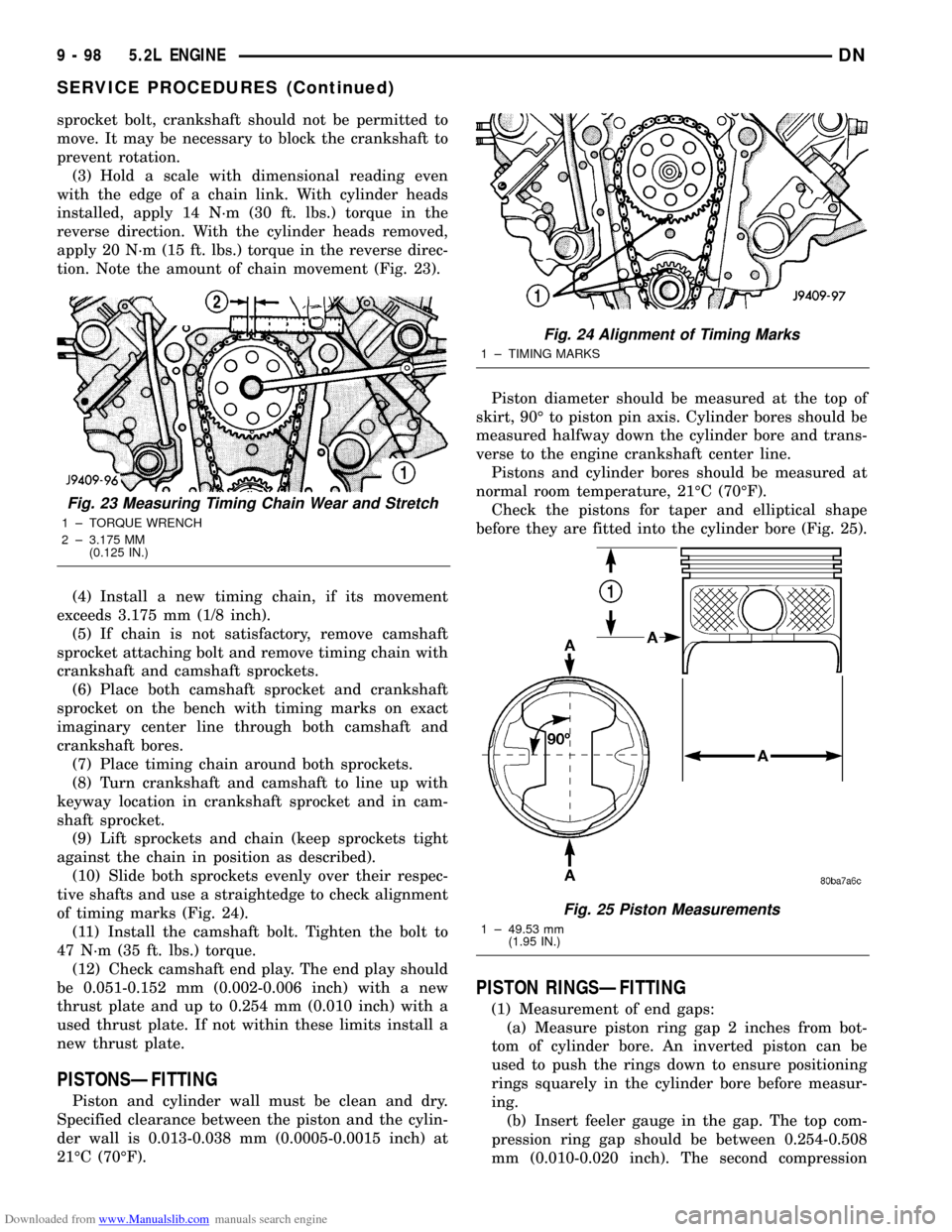
tion. Note the amount of chain movement (Fig. 23).
(4) Install a new timing chain, if its movement
exceeds 3.175 mm (1/8 inch).
(5) If chain is not satisfactory, remove camshaft
sprocket attaching bolt and remove timing chain with
crankshaft and camshaft sprockets.
(6) Place both camshaft sprocket and crankshaft
sprocket on the bench with timing marks on exact
imaginary center line through both camshaft and
crankshaft bores.
(7) Place timing chain around both sprockets.
(8) Turn crankshaft and camshaft to line up with
keyway location in crankshaft sprocket and in cam-
shaft sprocket.
(9) Lift sprockets and chain (keep sprockets tight
against the chain in position as described).
(10) Slide both sprockets evenly over their respec-
tive shafts and use a straightedge to check alignment
of timing marks (Fig. 24).
(11) Install the camshaft bolt. Tighten the bolt to
47 N´m (35 ft. lbs.) torque.
(12) Check camshaft end play. The end play should
be 0.051-0.152 mm (0.002-0.006 inch) with a new
thrust plate and up to 0.254 mm (0.010 inch) with a
used thrust plate. If not within these limits install a
new thrust plate.
PISTONSÐFITTING
Piston and cylinder wall must be clean and dry.
Specified clearance between the piston and the cylin-
der wall is 0.013-0.038 mm (0.0005-0.0015 inch) at
21ÉC (70ÉF).Piston diameter should be measured at the top of
skirt, 90É to piston pin axis. Cylinder bores should be
measured halfway down the cylinder bore and trans-
verse to the engine crankshaft center line.
Pistons and cylinder bores should be measured at
normal room temperature, 21ÉC (70ÉF).
Check the pistons for taper and elliptical shape
before they are fitted into the cylinder bore (Fig. 25).
PISTON RINGSÐFITTING
(1) Measurement of end gaps:
(a) Measure piston ring gap 2 inches from bot-
tom of cylinder bore. An inverted piston can be
used to push the rings down to ensure positioning
rings squarely in the cylinder bore before measur-
ing.
(b) Insert feeler gauge in the gap. The top com-
pression ring gap should be between 0.254-0.508
mm (0.010-0.020 inch). The second compression
Fig. 23 Measuring Timing Chain Wear and Stretch
1 ± TORQUE WRENCH
2 ± 3.175 MM
(0.125 IN.)
Fig. 24 Alignment of Timing Marks
1 ± TIMING MARKS
Fig. 25 Piston Measurements
1 ± 49.53 mm
(1.95 IN.)
9 - 98 5.2L ENGINEDN
SERVICE PROCEDURES (Continued)
Page 103 of 193
Downloaded from www.Manualslib.com manuals search engine (9) Disconnect the accelerator linkage.
(10) Remove throttle body.
(11) Perform the Fuel System Pressure release
procedure (refer to Group 14, fuel System).
(12) Disconnect the fuel supply line.
(13) Disconnect the starter wires.
(14) Disconnect the oil pressure sending unit wire.
(15) Discharge the air conditioning system, if
equipped (refer to Group 24, Heating and Air Condi-
tioning for service procedures).
(16) Disconnect the air conditioning hoses.
(17) Disconnect the power steering hoses, if
equipped.
(18) Remove starter motor (refer to Group 8B, Bat-
tery/Starter/Generator Service).
(19) Remove the generator (refer to Group 8B, Bat-
tery/Starter/Generator Service).
(20) Raise and support the vehicle on a hoist.
(21) Disconnect exhaust pipe at manifold.
(22) Refer to Group 21, Transmissions for trans-
mission removal.
CAUTION: DO NOT lift the engine by the intake
manifold.
(23) Install an engine lifting fixture.
(24) The engine and front driving axle (engine/ax-
le/transmission) are connected through insulators
and support brackets. Separate the engine as follows:
²LEFT SIDEÐRemove 2 bolts attaching
(engine/pinion nose/transmission) bracket to trans-
mission bell housing. Remove 2 bracket to pinion
nose adaptor bolts. Separate engine from insulator by
removing upper nut washer assembly and bolt from
engine support bracket.
²RIGHT SIDEÐRemove 2 bracket to axle (dis-
connect housing) bolts and a bracket to bell housing
bolt. Separate engine from insulator by removing
upper nut washer assembly and bolt from engine
support bracket.
(25) Lower the vehicle.
(26) Install engine assembly on engine repair
stand.
INSTALLATION
(1) Remove engine from the repair stand and posi-
tion in the engine compartment.
(2) Install an engine support fixture.
(3) Raise and support the vehicle on a hoist.
(4) Install the engine front mounts.
(5) Refer to Group, 21 Transmissions for transmis-
sion installation
(6) Install the inspection plate.
(7) Remove transmission support.
(8) Install exhaust pipe to manifold.
(9) Lower the vehicle.
(10) Remove engine lifting fixture.(11) Install the generator (refer to Group 8B, Bat-
tery/Starter/Generator Service).
(12) Install starter motor (refer to Group 8B, Bat-
tery/Starter/Generator Service).
(13) Connect power steering hoses, if equipped.
(14) Connect air conditioning hoses.
(15) Evacuate and charge the air conditioning sys-
tem, if equipped (refer to Group 24, Heater and Air
Conditioning for service procedures).
(16) Using a new gasket, install throttle body.
Tighten the throttle body bolts to 23 N´m (200 in.
lbs.) torque.
(17) Connect the accelerator linkage.
(18) Connect the starter wires.
(19) Connect the oil pressure sending unit wire.
(20) Install the distributor cap and wiring.
(21) Connect the vacuum supply lines to the
intake manifold.
(22) Connect the fuel supply lines.
(23) Install the radiator (refer to Group 7, Cooling
System). Connect the radiator hoses and heater
hoses.
(24) Install fan shroud in position.
(25) Fill cooling system (refer to Group 7, Cooling
System for the proper procedure).
(26) Install the air cleaner.
(27) Install the battery.
(28) Warm engine and adjust.
(29) Install hood and line up with the scribe
marks.
(30) Road test vehicle.
INTAKE MANIFOLD
REMOVAL
(1) Disconnect the battery negative cable.
(2) Drain the cooling system. Refer to COOLING
SYSTEM.
(3) Remove the A/C compressor. Refer to HEAT-
ING and AIR CONDITIONING.
(4) Remove the generator. Refer to CHARGING
SYSTEM.
(5) Remove the accessory drive bracket.
(6) Remove the air cleaner assembly and air inlet
hose.
(7) Perform the fuel pressure release procedure.
Refer to FUEL SYSTEM.
(8) Disconnect the fuel supply line from the fuel
rail. Refer to FUEL SYSTEM.
(9) Disconnect the accelerator linkage and, if so
equipped, the speed control and transmission kick-
down cables.
(10) Remove the distributor cap and wires.
(11) Disconnect the coil wires.
(12) Disconnect the coolant temperature sending
unit wire.
DN5.2L ENGINE 9 - 103
REMOVAL AND INSTALLATION (Continued)
Page 105 of 193
Downloaded from www.Manualslib.com manuals search engine place, inspect to make sure seals are in place.
Remove alignment studs if used.
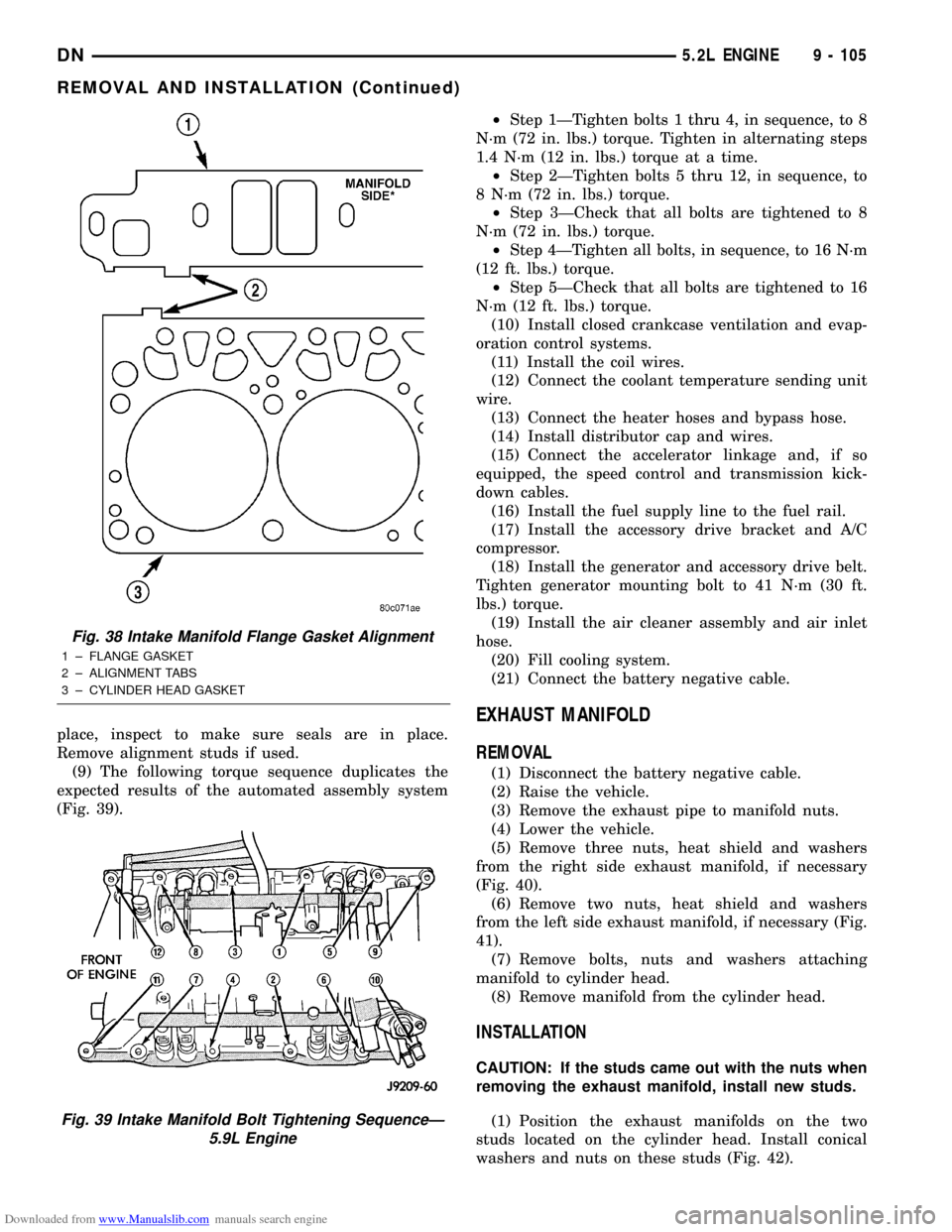
(9) The following torque sequence duplicates the
expected results of the automated assembly system
(Fig. 39).²Step 1ÐTighten bolts 1 thru 4, in sequence, to 8
N´m (72 in. lbs.) torque. Tighten in alternating steps
1.4 N´m (12 in. lbs.) torque at a time.
²Step 2ÐTighten bolts 5 thru 12, in sequence, to
8 N´m (72 in. lbs.) torque.
²Step 3ÐCheck that all bolts are tightened to 8
N´m (72 in. lbs.) torque.
²Step 4ÐTighten all bolts, in sequence, to 16 N´m
(12 ft. lbs.) torque.
²Step 5ÐCheck that all bolts are tightened to 16
N´m (12 ft. lbs.) torque.
(10) Install closed crankcase ventilation and evap-
oration control systems.
(11) Install the coil wires.
(12) Connect the coolant temperature sending unit
wire.
(13) Connect the heater hoses and bypass hose.
(14) Install distributor cap and wires.
(15) Connect the accelerator linkage and, if so
equipped, the speed control and transmission kick-
down cables.
(16) Install the fuel supply line to the fuel rail.
(17) Install the accessory drive bracket and A/C
compressor.
(18) Install the generator and accessory drive belt.
Tighten generator mounting bolt to 41 N´m (30 ft.
lbs.) torque.
(19) Install the air cleaner assembly and air inlet
hose.
(20) Fill cooling system.
(21) Connect the battery negative cable.
EXHAUST MANIFOLD
REMOVAL
(1) Disconnect the battery negative cable.
(2) Raise the vehicle.
(3) Remove the exhaust pipe to manifold nuts.
(4) Lower the vehicle.
(5) Remove three nuts, heat shield and washers
from the right side exhaust manifold, if necessary
(Fig. 40).
(6) Remove two nuts, heat shield and washers
from the left side exhaust manifold, if necessary (Fig.
41).
(7) Remove bolts, nuts and washers attaching
manifold to cylinder head.
(8) Remove manifold from the cylinder head.
INSTALLATION
CAUTION: If the studs came out with the nuts when
removing the exhaust manifold, install new studs.
(1) Position the exhaust manifolds on the two
studs located on the cylinder head. Install conical
washers and nuts on these studs (Fig. 42).
Fig. 38 Intake Manifold Flange Gasket Alignment
1 ± FLANGE GASKET
2 ± ALIGNMENT TABS
3 ± CYLINDER HEAD GASKET
Fig. 39 Intake Manifold Bolt Tightening SequenceÐ
5.9L Engine
DN5.2L ENGINE 9 - 105
REMOVAL AND INSTALLATION (Continued)
Page 109 of 193
Downloaded from www.Manualslib.com manuals search engine spring seat in cylinder head to the bottom surface of
spring retainer. If spacers are installed, measure
from the top of spacer. If height is greater than 42.86
mm (1-11/16 inches), install a 1.587 mm (1/16 inch)
spacer in head counterbore. This should bring spring
height back to normal 41.27 to 42.86 mm (1-5/8 to
1-11/16 inch).
HYDRAULIC TAPPETS
REMOVAL
(1) Remove the air cleaner assembly and air inlet
hose.
(2) Remove cylinder head cover, rocker assembly
and push rods. Identify push rods to ensure installa-
tion in original location.
(3) Remove intake manifold, yoke retainer and
aligning yokes.
(4) Slide Hydraulic Tappet Remover/Installer Tool
C-4129-A through opening in cylinder head and seat
tool firmly in the head of tappet.
(5) Pull tappet out of bore with a twisting motion.
If all tappets are to be removed, identify tappets to
ensure installation in original location.
INSTALLATION
(1) If the tappet or bore in cylinder block is scored,
scuffed, or shows signs of sticking, ream the bore to
next oversize. Replace with oversize tappet.
(2) Lubricate tappets.
(3) Install tappets and push rods in their original
positions. Ensure that the oil feed hole in the side of
the tappet body faces up (away from the crankshaft).
(4) Install aligning yokes with ARROW toward
camshaft.
(5) Install yoke retainer. Tighten the bolts to 23
N´m (200 in. lbs.) torque. Install intake manifold.
(6) Install push rods in original positions.
(7) Install rocker arm.
(8) Install cylinder head cover.
(9) Install air cleaner assembly and air inlet hose.
(10) Start and operate engine. Warm up to normal
operating temperature.
CAUTION: To prevent damage to valve mechanism,
engine must not be run above fast idle until all
hydraulic tappets have filled with oil and have
become quiet.
VIBRATION DAMPER
REMOVAL
(1) Disconnect the negative cable from the battery.
(2) Remove fan shroud retainer bolts and set
shroud back over engine.(3) Remove the cooling system fan.
(4) Remove the serpentine belt (refer to Group 7,
Cooling System).
(5) Remove the vibration damper pulley.
(6) Remove vibration damper bolt and washer from
end of crankshaft.
(7) Install bar and screw from Puller Tool Set
C-3688. Install 2 bolts with washers through the
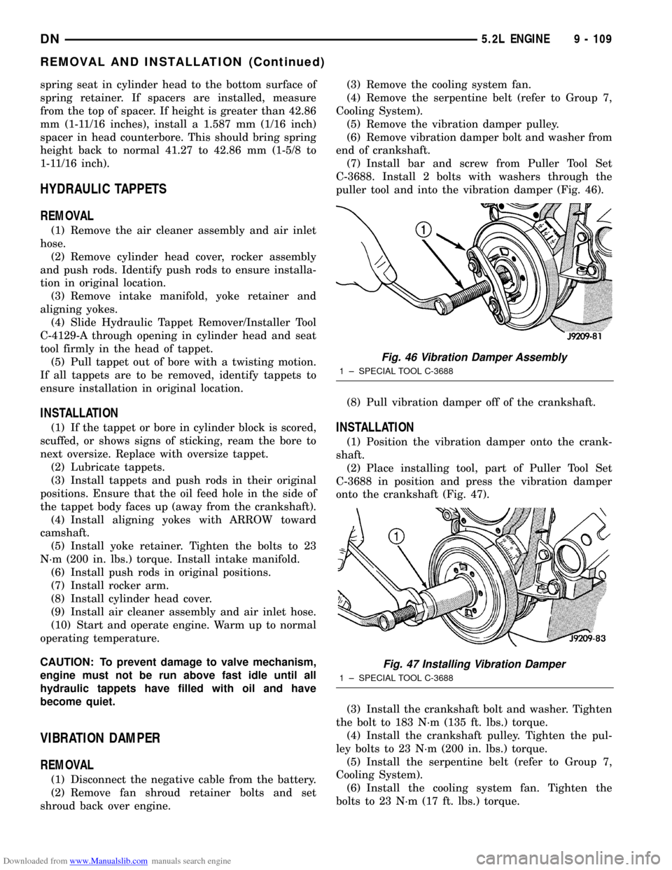
puller tool and into the vibration damper (Fig. 46).
(8) Pull vibration damper off of the crankshaft.
INSTALLATION
(1) Position the vibration damper onto the crank-
shaft.
(2) Place installing tool, part of Puller Tool Set
C-3688 in position and press the vibration damper
onto the crankshaft (Fig. 47).
(3) Install the crankshaft bolt and washer. Tighten
the bolt to 183 N´m (135 ft. lbs.) torque.
(4) Install the crankshaft pulley. Tighten the pul-
ley bolts to 23 N´m (200 in. lbs.) torque.
(5) Install the serpentine belt (refer to Group 7,
Cooling System).
(6) Install the cooling system fan. Tighten the
bolts to 23 N´m (17 ft. lbs.) torque.
Fig. 46 Vibration Damper Assembly
1 ± SPECIAL TOOL C-3688
Fig. 47 Installing Vibration Damper
1 ± SPECIAL TOOL C-3688
DN5.2L ENGINE 9 - 109
REMOVAL AND INSTALLATION (Continued)
Page 147 of 193
Downloaded from www.Manualslib.com manuals search engine Ensure the battery is completely charged and the
engine starter motor is in good operating condition.
Otherwise, the indicated compression pressures may
not be valid for diagnosis purposes.
(1) Clean the spark plug recesses with compressed
air.
(2) Remove the spark plugs.
(3) Secure the throttle in the wide-open position.
(4) Disconnect the ignition coil.
(5) Insert a compression pressure gauge and rotate
the engine with the engine starter motor for three
revolutions.
(6) Record the compression pressure on the third
revolution. Continue the test for the remaining cylin-
ders.
Refer to Engine Specifications for the correct
engine compression pressures.
CYLINDER HEAD GASKET FAILURE DIAGNOSIS
A cylinder head gasket leak can be located between
adjacent cylinders or between a cylinder and the
adjacent water jacket.
²Possible indications of the cylinder head gasket
leaking between adjacent cylinders are:
²Loss of engine power
²Engine misfiring
²Poor fuel economy
²Possible indications of the cylinder head gasket
leaking between a cylinder and an adjacent water
jacket are:
²Engine overheating
²Loss of coolant
²Excessive steam (white smoke) emitting from
exhaust
²Coolant foaming
CYLINDER-TO-CYLINDER LEAKAGE TEST
To determine if an engine cylinder head gasket is
leaking between adjacent cylinders, follow the proce-
dures in Cylinder Compression Pressure Test in this
section. An engine cylinder head gasket leaking
between adjacent cylinders will result in approxi-
mately a 50±70% reduction in compression pressure.
CYLINDER-TO-WATER JACKET LEAKAGE TEST
WARNING: USE EXTREME CAUTION WHEN THE
ENGINE IS OPERATING WITH COOLANT PRES-
SURE CAP REMOVED.
VISUAL TEST METHOD
With the engine cool, remove the coolant pressure
cap. Start the engine and allow it to warm up until
thermostat opens.
If a large combustion/compression pressure leak
exists, bubbles will be visible in the coolant.COOLING SYSTEM TESTER METHOD
WARNING: WITH COOLING SYSTEM TESTER IN
PLACE, PRESSURE WILL BUILD UP FAST. EXCES-
SIVE PRESSURE BUILT UP, BY CONTINUOUS
ENGINE OPERATION, MUST BE RELEASED TO A
SAFE PRESSURE POINT. NEVER PERMIT PRES-
SURE TO EXCEED 138 kPa (20 psi).
Install Cooling System Tester 7700 or equivalent to
pressure cap neck. Start the engine and observe the
tester's pressure gauge. If gauge pulsates with every
power stroke of a cylinder a combustion pressure
leak is evident.
CHEMICAL TEST METHOD
Combustion leaks into the cooling system can also
be checked by using Bloc-Chek Kit C-3685-A or
equivalent. Perform test following the procedures
supplied with the tool kit.
CYLINDER COMBUSTION PRESSURE LEAKAGE
TEST
The combustion pressure leakage test provides an
accurate means for determining engine condition.
Combustion pressure leakage testing will detect:
²Exhaust and intake valve leaks (improper seat-
ing)
²Leaks between adjacent cylinders or into water
jacket
²Any causes for combustion/compression pressure
loss
WARNING: DO NOT REMOVE THE RADIATOR CAP
WITH THE SYSTEM HOT AND UNDER PRESSURE.
SERIOUS BURNS FROM HOT COOLANT CAN
OCCUR.
Check the coolant level and fill as required. DO
NOT install the radiator cap.
Start and operate the engine until it attains nor-
mal operating temperature, then turn OFF the
engine.
Remove the spark plugs.
Remove the oil filler cap.
Remove the air cleaner.
Calibrate the tester according to the manufactur-
er's instructions. The shop air source for testing
should maintain 483 kPa (70 psi) minimum, 1,379
kPa (200 psi) maximum and 552 kPa (80 psi) recom-
mended.
Perform the test procedure on each cylinder accord-
ing to the tester manufacturer's instructions. While
testing, listen for pressurized air escaping through
the throttle body, tailpipe or oil filler cap opening.
Check for bubbles in the radiator coolant.
9 - 146 5.9L ENGINEDN
DIAGNOSIS AND TESTING (Continued)
Page 149 of 193
Downloaded from www.Manualslib.com manuals search engine HYDRAULIC TAPPETS
Before disassembling any part of the engine to cor-
rect tappet noise, check the oil pressure. If vehicle
has no oil pressure gauge, install a reliable gauge at
the pressure sending-unit. The pressure should be
between 207-552 kPa (30-80 psi) at 3,000 RPM.
Check the oil level after the engine reaches normal
operating temperature. Allow 5 minutes to stabilize
oil level, check dipstick. The oil level in the pan
should never be above the FULL mark or below the
ADD OIL mark on dipstick. Either of these two con-
ditions could be responsible for noisy tappets.
OIL LEVEL
HIGH
If oil level is above the FULL mark, it is possible
for the connecting rods to dip into the oil. With the
engine running, this condition could create foam in
the oil pan. Foam in oil pan would be fed to the
hydraulic tappets by the oil pump causing them to
lose length and allow valves to seat noisily.
LOW
Low oil level may allow oil pump to take in air.
When air is fed to the tappets, they lose length,
which allows valves to seat noisily. Any leaks on
intake side of oil pump through which air can be
drawn will create the same tappet action. Check the
lubrication system from the intake strainer to the
pump cover, including the relief valve retainer cap.
When tappet noise is due to aeration, it may be
intermittent or constant, and usually more than one
tappet will be noisy. When oil level and leaks have
been corrected, operate the engine at fast idle. Run
engine for a sufficient time to allow all of the air
inside the tappets to be bled out.
TAPPET NOISE DIAGNOSIS
(1) To determine source of tappet noise, operate
engine at idle with cylinder head covers removed.
(2) Feel each valve spring or rocker arm to detect
noisy tappet. The noisy tappet will cause the affected
spring and/or rocker arm to vibrate or feel rough in
operation.
NOTE: Worn valve guides or cocked springs are
sometimes mistaken for noisy tappets. If such is
the case, noise may be dampened by applying side
thrust on the valve spring. If noise is not apprecia-
bly reduced, it can be assumed the noise is in the
tappet. Inspect the rocker arm push rod sockets
and push rod ends for wear.
(3) Valve tappet noise ranges from light noise to a
heavy click. A light noise is usually caused by exces-
sive leak-down around the unit plunger, or by theplunger partially sticking in the tappet body cylinder.
The tappet should be replaced. A heavy click is
caused by a tappet check valve not seating, or by for-
eign particles wedged between the plunger and the
tappet body. This will cause the plunger to stick in
the down position. This heavy click will be accompa-
nied by excessive clearance between the valve stem
and rocker arm as valve closes. In either case, tappet
assembly should be removed for inspection and clean-
ing.
(4) The valve train generates a noise very much
like a light tappet noise during normal operation.
Care must be taken to ensure that tappets are mak-
ing the noise. If more than one tappet seems to be
noisy, it's probably not the tappets.
LEAK-DOWN TEST
After cleaning and inspection, test each tappet for
specified leak-down rate tolerance to ensure zero-lash
operation (Fig. 11).
Swing the weighted arm of the hydraulic valve tap-
pet tester away from the ram of the Universal Leak-
Down Tester.
(1) Place a 7.925-7.950 mm (0.312-0.313 inch)
diameter ball bearing on the plunger cap of the tap-
pet.
(2) Lift the ram and position the tappet (with the
ball bearing) inside the tester cup.
(3) Lower the ram, then adjust the nose of the ram
until it contacts the ball bearing. DO NOT tighten
the hex nut on the ram.
(4) Fill the tester cup with hydraulic valve tappet
test oil until the tappet is completely submerged.
(5) Swing the weighted arm onto the push rod and
pump the tappet plunger up and down to remove air.
When the air bubbles cease, swing the weighted arm
away and allow the plunger to rise to the normal
position.
(6) Adjust the nose of the ram to align the pointer
with the SET mark on the scale of the tester and
tighten the hex nut.
(7) Slowly swing the weighted arm onto the push
rod.
(8) Rotate the cup by turning the handle at the
base of the tester clockwise one revolution every 2
seconds.
(9) Observe the leak-down time interval from the
instant the pointer aligns with the START mark on
the scale until the pointer aligns with the 0.125
mark. A normally functioning tappet will require
20-110 seconds to leak-down. Discard tappets with
leak-down time interval not within this specification.
ENGINE OIL PRESSURE
(1) Remove oil pressure sending unit.
9 - 148 5.9L ENGINEDN
DIAGNOSIS AND TESTING (Continued)
Page 151 of 193
Downloaded from www.Manualslib.com manuals search engine (2) Check intake manifold bolt torque.
(3) Perform cylinder compression test. Refer to
Cylinder Compression Pressure Test in the Engine
Diagnosis area of this section.
(4) Clean or replace spark plugs as necessary and
adjust gap as specified in Electrical Group 8D.
Tighten to specifications.
(5) Test resistance of spark plug cables. Refer to
Electrical Group 8D, Spark Plug Cables.
(6) Inspect the primary wires. Test coil output volt-
age and primary resistance. Replace parts as neces-
sary. Refer to Electrical Group 8D, for specifications.
(7) Test fuel pump for pressure. Refer to Group 14,
Fuel System Specifications.
(8) The air filter elements should be replaced as
specified in Lubrication and Maintenance, Group 0.
(9) Inspect crankcase ventilation system as out
lined in Group 0, Lubrication and Maintenance. For
emission controls see Group 25, Emission Controls
for service procedures.
(10) Road test vehicle as a final test.
ENGINE OIL
WARNING: NEW OR USED ENGINE OIL CAN BE
IRRITATING TO THE SKIN. AVOID PROLONGED OR
REPEATED SKIN CONTACT WITH ENGINE OIL.
CONTAMINANTS IN USED ENGINE OIL, CAUSED BY
INTERNAL COMBUSTION, CAN BE HAZARDOUS TO
YOUR HEALTH. THOROUGHLY WASH EXPOSED
SKIN WITH SOAP AND WATER. DO NOT WASH
SKIN WITH GASOLINE, DIESEL FUEL, THINNER, OR
SOLVENTS, HEALTH PROBLEMS CAN RESULT. DO
NOT POLLUTE, DISPOSE OF USED ENGINE OIL
PROPERLY.
ENGINE OIL SPECIFICATION
CAUTION: Do not use non-detergent or straight
mineral oil when adding or changing crankcase
lubricant. Engine failure can result.
API SERVICE GRADE CERTIFIED
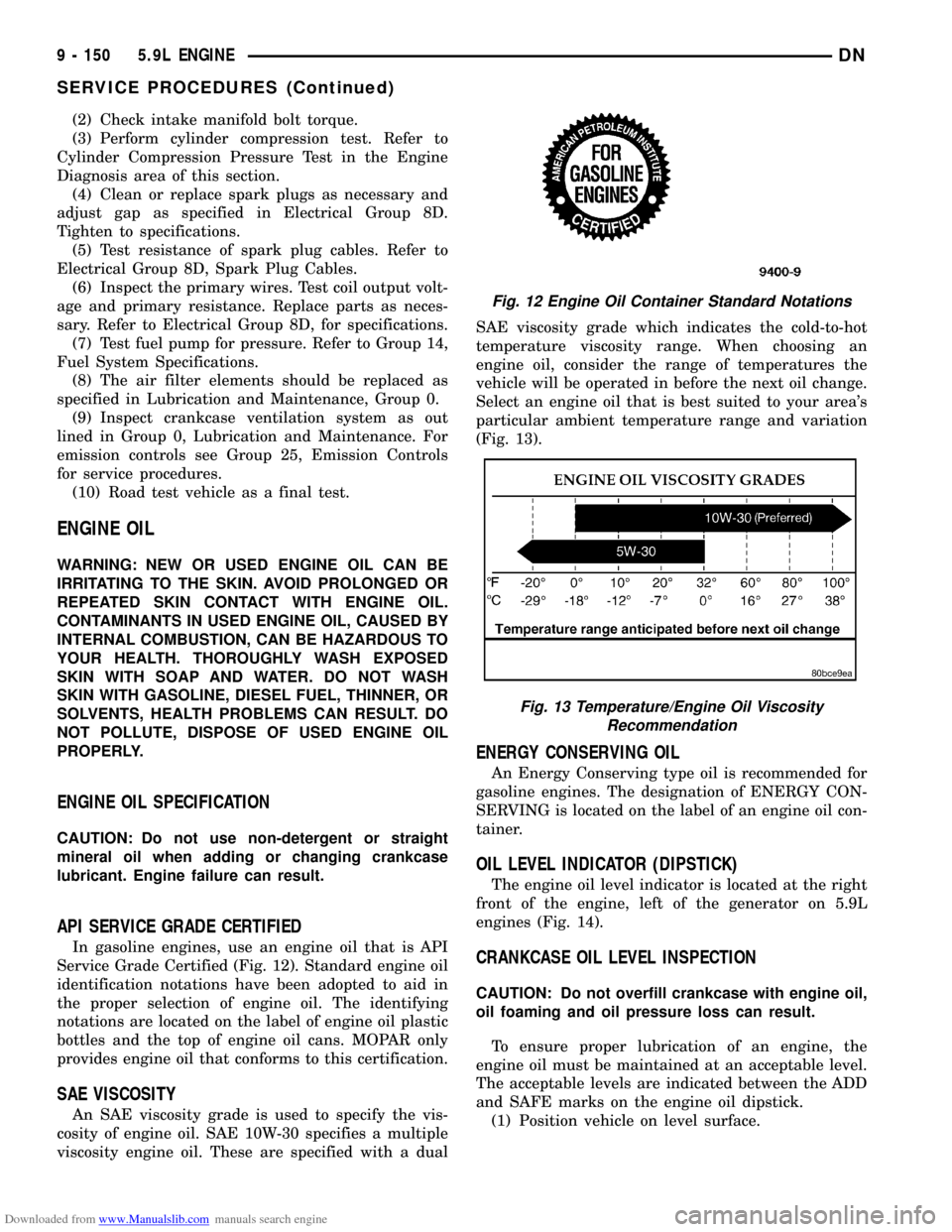
In gasoline engines, use an engine oil that is API
Service Grade Certified (Fig. 12). Standard engine oil
identification notations have been adopted to aid in
the proper selection of engine oil. The identifying
notations are located on the label of engine oil plastic
bottles and the top of engine oil cans. MOPAR only
provides engine oil that conforms to this certification.
SAE VISCOSITY
An SAE viscosity grade is used to specify the vis-
cosity of engine oil. SAE 10W-30 specifies a multiple
viscosity engine oil. These are specified with a dualSAE viscosity grade which indicates the cold-to-hot
temperature viscosity range. When choosing an
engine oil, consider the range of temperatures the
vehicle will be operated in before the next oil change.
Select an engine oil that is best suited to your area's
particular ambient temperature range and variation
(Fig. 13).
ENERGY CONSERVING OIL
An Energy Conserving type oil is recommended for
gasoline engines. The designation of ENERGY CON-
SERVING is located on the label of an engine oil con-
tainer.
OIL LEVEL INDICATOR (DIPSTICK)
The engine oil level indicator is located at the right
front of the engine, left of the generator on 5.9L
engines (Fig. 14).
CRANKCASE OIL LEVEL INSPECTION
CAUTION: Do not overfill crankcase with engine oil,
oil foaming and oil pressure loss can result.
To ensure proper lubrication of an engine, the
engine oil must be maintained at an acceptable level.
The acceptable levels are indicated between the ADD
and SAFE marks on the engine oil dipstick.
(1) Position vehicle on level surface.
Fig. 12 Engine Oil Container Standard Notations
Fig. 13 Temperature/Engine Oil Viscosity
Recommendation
9 - 150 5.9L ENGINEDN
SERVICE PROCEDURES (Continued)
Page 157 of 193
Downloaded from www.Manualslib.com manuals search engine (7) Place timing chain around both sprockets.
(8) Turn crankshaft and camshaft to line up with
keyway location in crankshaft sprocket and in cam-
shaft sprocket.
(9) Lift sprockets and chain (keep sprockets tight
against the chain in position as described).
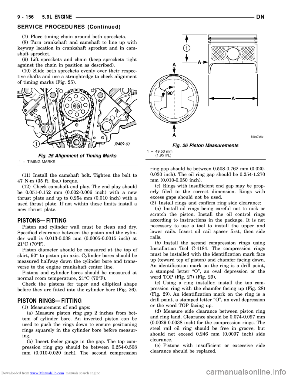
(10) Slide both sprockets evenly over their respec-
tive shafts and use a straightedge to check alignment
of timing marks (Fig. 25).
(11) Install the camshaft bolt. Tighten the bolt to
47 N´m (35 ft. lbs.) torque.
(12) Check camshaft end play. The end play should
be 0.051-0.152 mm (0.002-0.006 inch) with a new
thrust plate and up to 0.254 mm (0.010 inch) with a
used thrust plate. If not within these limits install a
new thrust plate.
PISTONSÐFITTING
Piston and cylinder wall must be clean and dry.
Specified clearance between the piston and the cylin-
der wall is 0.013-0.038 mm (0.0005-0.0015 inch) at
21ÉC (70ÉF).
Piston diameter should be measured at the top of
skirt, 90É to piston pin axis. Cylinder bores should be
measured halfway down the cylinder bore and trans-
verse to the engine crankshaft center line.
Pistons and cylinder bores should be measured at
normal room temperature, 21ÉC (70ÉF).
Check the pistons for taper and elliptical shape
before they are fitted into the cylinder bore (Fig. 26).
PISTON RINGSÐFITTING
(1) Measurement of end gaps:
(a) Measure piston ring gap 2 inches from bot-
tom of cylinder bore. An inverted piston can be
used to push the rings down to ensure positioning
rings squarely in the cylinder bore before measur-
ing.
(b) Insert feeler gauge in the gap. The top com-
pression ring gap should be between 0.254-0.508
mm (0.010-0.020 inch). The second compressionring gap should be between 0.508-0.762 mm (0.020-
0.030 inch). The oil ring gap should be 0.254-1.270
mm (0.010-0.050 inch).
(c) Rings with insufficient end gap may be prop-
erly filed to the correct dimension. Rings with
excess gaps should not be used.
(2) Install rings and confirm ring side clearance:
(a) Install oil rings being careful not to nick or
scratch the piston. Install the oil control rings
according to instructions in the package. It is not
necessary to use a tool to install the upper and
lower rails. Insert oil rail spacer first, then side
rails.
(b) Install the second compression rings using
Installation Tool C-4184. The compression rings
must be installed with the identification mark face
up (toward top of piston) and chamfer facing down.
An identification mark on the ring is a drill point,
a stamped letter ªOº, an oval depression or the
word TOP (Fig. 27) (Fig. 29).
(c) Using a ring installer, install the top com-
pression ring with the chamfer facing up (Fig. 28)
(Fig. 29). An identification mark on the ring is a
drill point, a stamped letter ªOº, an oval depression
or the word TOP facing up.
(d) Measure side clearance between piston ring
and ring land. Clearance should be 0.074-0.097 mm
(0.0029-0.0038 inch) for the compression rings. The
steel rail oil ring should be free in groove, but
should not exceed 0.246 mm (0.0097 inch) side
clearance.
(e) Pistons with insufficient or excessive side
clearance should be replaced.
Fig. 25 Alignment of Timing Marks
1 ± TIMING MARKS
Fig. 26 Piston Measurements
1 ± 49.53 mm
(1.95 IN.)
9 - 156 5.9L ENGINEDN
SERVICE PROCEDURES (Continued)
Page 164 of 193
Downloaded from www.Manualslib.com manuals search engine INTAKE MANIFOLD
REMOVAL
(1) Disconnect the battery negative cable.
(2) Drain the cooling system. Refer to COOLING
SYSTEM.
(3) Remove the A/C compressor. Refer to HEAT-
ING and AIR CONDITIONING.
(4) Remove the generator. Refer to CHARGING
SYSTEM.
(5) Remove the accessory drive bracket.
(6) Remove the air cleaner assembly and air inlet
hose.
(7) Perform the fuel pressure release procedure.
Refer to FUEL SYSTEM.
(8) Disconnect the fuel supply line from the fuel
rail. Refer to FUEL SYSTEM.
(9) Disconnect the accelerator linkage and, if so
equipped, the speed control and transmission kick-
down cables.
(10) Remove the distributor cap and wires.
(11) Disconnect the coil wires.
(12) Disconnect the coolant temperature sending
unit wire.
(13) Disconnect the heater hoses and bypass hose.
(14) Remove the closed crankcase ventilation and
evaporation control systems.
(15) Remove intake manifold bolts.
(16) Lift the intake manifold and throttle body out
of the engine compartment as an assembly.
(17) Remove and discard the flange side gaskets
and the front and rear cross-over gaskets.
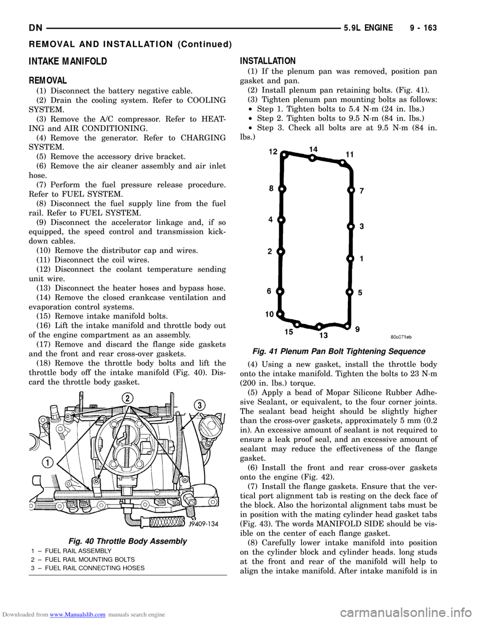
(18) Remove the throttle body bolts and lift the
throttle body off the intake manifold (Fig. 40). Dis-
card the throttle body gasket.
INSTALLATION
(1) If the plenum pan was removed, position pan
gasket and pan.
(2) Install plenum pan retaining bolts. (Fig. 41).
(3) Tighten plenum pan mounting bolts as follows:
²Step 1. Tighten bolts to 5.4 N´m (24 in. lbs.)
²Step 2. Tighten bolts to 9.5 N´m (84 in. lbs.)
²Step 3. Check all bolts are at 9.5 N´m (84 in.
lbs.)
(4) Using a new gasket, install the throttle body
onto the intake manifold. Tighten the bolts to 23 N´m
(200 in. lbs.) torque.
(5) Apply a bead of Mopar Silicone Rubber Adhe-
sive Sealant, or equivalent, to the four corner joints.
The sealant bead height should be slightly higher
than the cross-over gaskets, approximately 5 mm (0.2
in). An excessive amount of sealant is not required to
ensure a leak proof seal, and an excessive amount of
sealant may reduce the effectiveness of the flange
gasket.
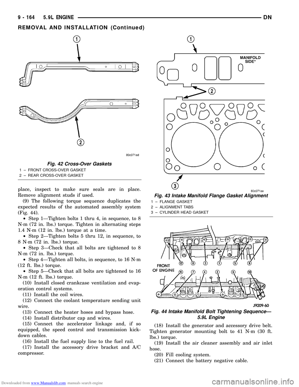
(6) Install the front and rear cross-over gaskets
onto the engine (Fig. 42).
(7) Install the flange gaskets. Ensure that the ver-
tical port alignment tab is resting on the deck face of
the block. Also the horizontal alignment tabs must be
in position with the mating cylinder head gasket tabs
(Fig. 43). The words MANIFOLD SIDE should be vis-
ible on the center of each flange gasket.
(8) Carefully lower intake manifold into position
on the cylinder block and cylinder heads. long studs
at the front and rear of the manifold will help to
align the intake manifold. After intake manifold is in
Fig. 40 Throttle Body Assembly
1 ± FUEL RAIL ASSEMBLY
2 ± FUEL RAIL MOUNTING BOLTS
3 ± FUEL RAIL CONNECTING HOSES
Fig. 41 Plenum Pan Bolt Tightening Sequence
DN5.9L ENGINE 9 - 163
REMOVAL AND INSTALLATION (Continued)
Page 165 of 193
Downloaded from www.Manualslib.com manuals search engine place, inspect to make sure seals are in place.
Remove alignment studs if used.
(9) The following torque sequence duplicates the
expected results of the automated assembly system
(Fig. 44).
²Step 1ÐTighten bolts 1 thru 4, in sequence, to 8
N´m (72 in. lbs.) torque. Tighten in alternating steps
1.4 N´m (12 in. lbs.) torque at a time.
²Step 2ÐTighten bolts 5 thru 12, in sequence, to
8 N´m (72 in. lbs.) torque.
²Step 3ÐCheck that all bolts are tightened to 8
N´m (72 in. lbs.) torque.
²Step 4ÐTighten all bolts, in sequence, to 16 N´m
(12 ft. lbs.) torque.
²Step 5ÐCheck that all bolts are tightened to 16
N´m (12 ft. lbs.) torque.
(10) Install closed crankcase ventilation and evap-
oration control systems.
(11) Install the coil wires.
(12) Connect the coolant temperature sending unit
wire.
(13) Connect the heater hoses and bypass hose.
(14) Install distributor cap and wires.
(15) Connect the accelerator linkage and, if so
equipped, the speed control and transmission kick-
down cables.
(16) Install the fuel supply line to the fuel rail.
(17) Install the accessory drive bracket and A/C
compressor.(18) Install the generator and accessory drive belt.
Tighten generator mounting bolt to 41 N´m (30 ft.
lbs.) torque.
(19) Install the air cleaner assembly and air inlet
hose.
(20) Fill cooling system.
(21) Connect the battery negative cable.
Fig. 42 Cross-Over Gaskets
1 ± FRONT CROSS-OVER GASKET
2 ± REAR CROSS-OVER GASKET
Fig. 43 Intake Manifold Flange Gasket Alignment
1 ± FLANGE GASKET
2 ± ALIGNMENT TABS
3 ± CYLINDER HEAD GASKET
Fig. 44 Intake Manifold Bolt Tightening SequenceÐ
5.9L Engine
9 - 164 5.9L ENGINEDN
REMOVAL AND INSTALLATION (Continued)