engine temperature DODGE DURANGO 1998 1.G Workshop Manual
[x] Cancel search | Manufacturer: DODGE, Model Year: 1998, Model line: DURANGO, Model: DODGE DURANGO 1998 1.GPages: 193, PDF Size: 5.65 MB
Page 12 of 193

Downloaded from www.Manualslib.com manuals search engine Otherwise the indicated compression pressures may
not be valid for diagnosis purposes.
(1) Clean the spark plug recesses with compressed
air.
(2) Remove the spark plugs.
(3) Secure the throttle in the wide-open position.
(4) Disable the fuel system. (Refer to Group 14,
Fuel System for the correct procedure)
(5) Disconnect the ignition coil.
(6) Insert a compression pressure gauge and rotate
the engine with the engine starter motor for three
revolutions.
(7) Record the compression pressure on the 3rd
revolution. Continue the test for the remaining cylin-
ders.
Refer to Engine Specifications for the correct
engine compression pressures.
CYLINDER HEAD GASKET FAILURE DIAGNOSIS
A cylinder head gasket leak can be located between
adjacent cylinders or between a cylinder and the
adjacent water jacket.
²Possible indications of the cylinder head gasket
leaking between adjacent cylinders are:
²Loss of engine power
²Engine misfiring
²Poor fuel economy
²Possible indications of the cylinder head gasket
leaking between a cylinder and an adjacent water
jacket are:
²Engine overheating
²Loss of coolant
²Excessive steam (white smoke) emitting from
exhaust
²Coolant foaming
CYLINDER-TO-CYLINDER LEAKAGE TEST
To determine if an engine cylinder head gasket is
leaking between adjacent cylinders, follow the proce-
dures in Cylinder Compression Pressure Test in this
section. An engine cylinder head gasket leaking
between adjacent cylinders will result in approxi-
mately a 50±70% reduction in compression pressure.
CYLINDER-TO-WATER JACKET LEAKAGE TEST
WARNING: USE EXTREME CAUTION WHEN THE
ENGINE IS OPERATING WITH COOLANT PRES-
SURE CAP REMOVED.
VISUAL TEST METHOD
With the engine cool, remove the coolant pressure
cap. Start the engine and allow it to warm up until
thermostat opens.
If a large combustion/compression pressure leak
exists, bubbles will be visible in the coolant.COOLING SYSTEM TESTER METHOD
WARNING: WITH COOLING SYSTEM TESTER IN
PLACE, PRESSURE WILL BUILD UP FAST. EXCES-
SIVE PRESSURE BUILT UP, BY CONTINUOUS
ENGINE OPERATION, MUST BE RELEASED TO A
SAFE PRESSURE POINT. NEVER PERMIT PRES-
SURE TO EXCEED 138 kPa (20 psi).
Install Cooling System Tester 7700 or equivalent to
pressure cap neck. Start the engine and observe the
tester's pressure gauge. If gauge pulsates with every
power stroke of a cylinder a combustion pressure
leak is evident.
CHEMICAL TEST METHOD
Combustion leaks into the cooling system can also
be checked by using Bloc-Chek Kit C-3685-A or
equivalent. Perform test following the procedures
supplied with the tool kit.
CYLINDER COMBUSTION PRESSURE LEAKAGE
TEST
The combustion pressure leakage test provides an
accurate means for determining engine condition.
Combustion pressure leakage testing will detect:
²Exhaust and intake valve leaks (improper seat-
ing).
²Leaks between adjacent cylinders or into water
jacket.
²Any causes for combustion/compression pressure
loss.
(1) Check the coolant level and fill as required. DO
NOT install the radiator cap.
(2) Start and operate the engine until it attains
normal operating temperature, then turn the engine
OFF.
(3) Remove the spark plugs.
(4) Remove the oil filler cap.
(5) Remove the air cleaner.
(6)
Calibrate the tester according to the manufacturer's
instructions. The shop air source for testing should main-
tain 483 kPa (70 psi) minimum, 1,379 kPa (200 psi) maxi-
mum and 552 kPa (80 psi) recommended.
(7) Perform the test procedures on each cylinder
according to the tester manufacturer's instructions.
While testing, listen for pressurized air escaping
through the throttle body, tailpipe and oil filler cap
opening. Check for bubbles in the radiator coolant.
All gauge pressure indications should be equal,
with no more than 25% leakage.
FOR EXAMPLE:At 552 kPa (80 psi) input pres-
sure, a minimum of 414 kPa (60 psi) should be main-
tained in the cylinder.
Refer to the Cylinder Combustion Pressure Leak-
age Test Diagnosis chart.
9 - 12 4.7L ENGINEDN
DIAGNOSIS AND TESTING (Continued)
Page 14 of 193

Downloaded from www.Manualslib.com manuals search engine filter runoff, and main bearing cap to cylinder
block mating surfaces.
(4) If no leaks are detected, pressurize the crank-
case as outlined in the, Inspection (Engine oil Leaks
in general)
CAUTION: Do not exceed 20.6 kPa (3 psi).
(5) If the leak is not detected, very slowly turn the
crankshaft and watch for leakage. If a leak is
detected between the crankshaft and seal while
slowly turning the crankshaft, it is possible the
crankshaft seal surface is damaged. The seal area on
the crankshaft could have minor nicks or scratches
that can be polished out with emery cloth.
CAUTION: Use extreme caution when crankshaft
polishing is necessary to remove minor nicks and
scratches. The crankshaft seal flange is especially
machined to complement the function of the rear oil
seal.
(6) For bubbles that remain steady with shaft
rotation, no further inspection can be done until dis-
assembled.
REAR SEAL AREA LEAKSÐINSPECTION
Since it is sometimes difficult to determine the
source of an oil leak in the rear seal area of the
engine, a more involved inspection is necessary. The
following steps should be followed to help pinpoint
the source of the leak.
If the leakage occurs at the crankshaft rear oil seal
area:
(1) Disconnect the battery.
(2) Raise the vehicle.
(3) Remove torque converter or clutch housing
cover and inspect rear of block for evidence of oil.
Use a black light to check for the oil leak:
(a) Circular spray pattern generally indicates
seal leakage or crankshaft damage.
(b) Where leakage tends to run straight down,
possible causes are a porous block, distributor seal,
camshaft bore cup plugs, oil galley pipe plugs, oil
filter runoff, and main bearing cap to cylinder
block mating surfaces. See Group 9, Engines, for
proper repair procedures of these items.
(4) If no leaks are detected, pressurized the crank-
case as outlined in the section, Inspection (Engine oil
Leaks in general)
CAUTION: Do not exceed 20.6 kPa (3 psi).
(5) If the leak is not detected, very slowly turn the
crankshaft and watch for leakage. If a leak is
detected between the crankshaft and seal while
slowly turning the crankshaft, it is possible thecrankshaft seal surface is damaged. The seal area on
the crankshaft could have minor nicks or scratches
that can be polished out with emery cloth.
CAUTION: Use extreme caution when crankshaft
polishing is necessary to remove minor nicks or
scratches. The crankshaft seal flange is specially
machined to complement the function of the rear oil
seal.
(6) For bubbles that remain steady with shaft
rotation, no further inspection can be done until dis-
assembled. Refer to the service DiagnosisÐMechani-
cal, under the Oil Leak row, for components
inspections on possible causes and corrections.
(7) After the oil leak root cause and appropriate
corrective action have been identified, Refer to Group
9, EnginesÐCrankshaft Rear Oil Seals, for proper
replacement procedures.
HYDRAULIC LASH ADJUSTER NOISE
DIAGNOSIS
A tappet-like noise may be produced from several
items. Check the following items.
(1) Engine oil level too high or too low. This may
cause aerated oil to enter the adjusters and cause
them to be spongy.
(2) Insufficient running time after rebuilding cylin-
der head. Low speed running up to 1 hour may be
required.
(3) Turn engine off and let set for a few minutes
before restarting. Repeat this several times after
engine has reached normal operating temperature.
(4) Low oil pressure.
(5) The oil restrictor in cylinder head gasket or the
oil passage to the cylinder head is plugged with
debris.
(6) Air ingested into oil due to broken or cracked
oil pump pick up.
(7) Worn valve guides.
(8) Rocker arm ears contacting valve spring
retainer.
(9) Rocker arm loose, adjuster stuck or at maxi-
mum extension and still leaves lash in the system.
(10) Faulty lash adjuster.
a. Check lash adjusters for sponginess while
installed in cylinder head and cam on camshaft at
base circle. Depress part of rocker arm over adjuster.
Normal adjusters should feel very firm. Spongy
adjusters can be bottomed out easily.
b. Remove suspected lash adjusters, and replace.
c. Before installation, make sure adjusters are at
least partially full of oil. This can be verified by little
or no plunger travel when lash adjuster is depressed.
9 - 14 4.7L ENGINEDN
DIAGNOSIS AND TESTING (Continued)
Page 16 of 193
Downloaded from www.Manualslib.com manuals search engine locating dowel is recommended during assembly to
prevent smearing the material off location.
ENGINE OIL
WARNING: NEW OR USED ENGINE OIL CAN BE
IRRITATING TO THE SKIN. AVOID PROLONGED OR
REPEATED SKIN CONTACT WITH ENGINE OIL.
CONTAMINANTS IN USED ENGINE OIL, CAUSED BY
INTERNAL COMBUSTION, CAN BE HAZARDOUS TO
YOUR HEALTH. THOROUGHLY WASH EXPOSED
SKIN WITH SOAP AND WATER. DO NOT WASH
SKIN WITH GASOLINE, DIESEL FUEL, THINNER, OR
SOLVENTS, HEALTH PROBLEMS CAN RESULT. DO
NOT POLLUTE, DISPOSE OF USED ENGINE OIL
PROPERLY.
ENGINE OIL SPECIFICATION
CAUTION: Do not use non-detergent or straight
mineral oil when adding or changing crankcase
lubricant. Engine failure can result.
API SERVICE GRADE CERTIFIED
Use an engine oil that is API Service Grade Certi-
fied. MOPARtprovides engine oils that conform to
this service grade.
SAE VISCOSITY
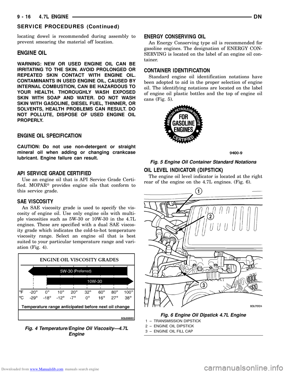
An SAE viscosity grade is used to specify the vis-
cosity of engine oil. Use only engine oils with multi-
ple viscosities such as 5W-30 or 10W-30 in the 4.7L
engines. These are specified with a dual SAE viscos-
ity grade which indicates the cold-to-hot temperature
viscosity range. Select an engine oil that is best
suited to your particular temperature range and vari-
ation (Fig. 4).
ENERGY CONSERVING OIL
An Energy Conserving type oil is recommended for
gasoline engines. The designation of ENERGY CON-
SERVING is located on the label of an engine oil con-
tainer.
CONTAINER IDENTIFICATION
Standard engine oil identification notations have
been adopted to aid in the proper selection of engine
oil. The identifying notations are located on the label
of engine oil plastic bottles and the top of engine oil
cans (Fig. 5).
OIL LEVEL INDICATOR (DIPSTICK)
The engine oil level indicator is located at the right
rear of the engine on the 4.7L engines. (Fig. 6).
Fig. 4 Temperature/Engine Oil ViscosityÐ4.7L
Engine
Fig. 5 Engine Oil Container Standard Notations
Fig. 6 Engine Oil Dipstick 4.7L Engine
1 ± TRANSMISSION DIPSTICK
2 ± ENGINE OIL DIPSTICK
3 ± ENGINE OIL FILL CAP
9 - 16 4.7L ENGINEDN
SERVICE PROCEDURES (Continued)
Page 31 of 193
Downloaded from www.Manualslib.com manuals search engine ENGINE ASSEMBLY
REMOVAL
NOTE: This procedure applies to both the 4X2 and
4X4 vehicles, steps that apply to the 4X4 vehicle
only, are identified.
(1) Disconnect the battery negative and positive
cables.
(2) Remove the battery and the battery tray. Refer
to BATTERY.
(3) Raise vehicle on hoist.
(4) Remove exhaust crossover pipe from exhaust
manifolds. Refer to EXHAUST SYSTEM.
(5)4X4 vehiclesDisconnect axle vent tube from
left side engine mount.
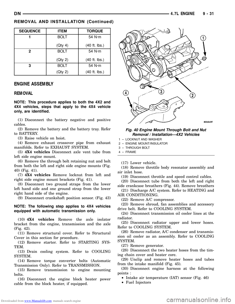
(6) Remove the through bolt retaining nut and bolt
from both the left and right side engine mounts (Fig.
40) (Fig. 41).
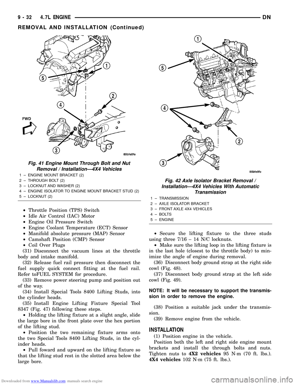
(7)4X4 vehiclesRemove locknut from left and
right side engine mount brackets (Fig. 41).
(8) Disconnect two ground straps from the lower
left hand side and one ground strap from the lower
right hand side of the engine.
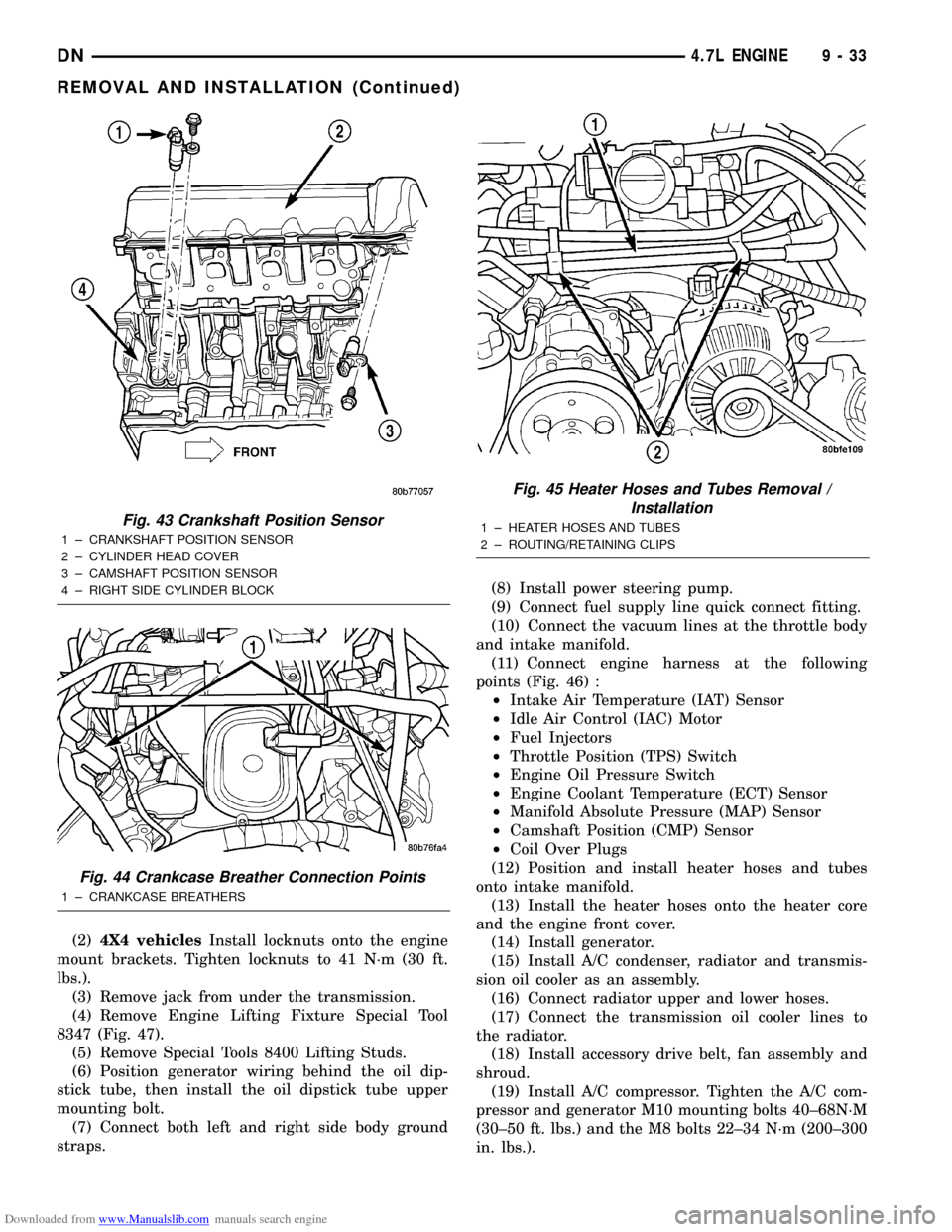
(9) Disconnect crankshaft position sensor. (Fig. 43)
NOTE: The following step applies to 4X4 vehicles
equipped with automatic transmission only.
(10)4X4 vehiclesRemove the axle isolator
bracket from the engine, transmission and the axle
(Fig. 42).
(11) Remove structural cover. Refer to Structural
Cover in this section for procedure.
(12) Remove starter. Refer to STARTING SYS-
TEM.
(13) Drain cooling system. Refer to COOLING
SYSTEM.
(14) Remove torque converter bolts (Automatic
Transmission Only). Refer to TRANSMISSION.
(15) Remove transmission to engine mounting
bolts.
(16) Disconnect the engine block heater power
cable from the block heater, if equipped.(17) Lower vehicle.
(18) Remove throttle body resonator assembly and
air inlet hose.
(19) Disconnect throttle and speed control cables.
(20) Disconnect tube from both the left and right
side crankcase breathers (Fig. 44). Remove breathers
(21) Discharge A/C system. Refer to HEATING and
AIR CONDITIONING.
(22) Remove A/C compressor.
(23) Remove shroud, fan assemblies and accessory
drive belt. Refer to COOLING SYSTEM.
(24) Disconnect transmission oil cooler lines at the
radiator.
(25) Disconnect radiator upper and lower hoses.
Refer to COOLING SYSTEM.
(26) Remove radiator, A/C condenser and transmis-
sion oil cooler as an assembly. Refer to COOLING
SYSTEM.
(27) Remove generator.
(28) Disconnect the two heater hoses from the tim-
ing chain cover and heater core.
(29) Unclip and remove heater hoses and tubes
from the intake manifold (Fig. 45).
(30) Disconnect engine harness at the following
points :
²Intake air temperature (IAT) sensor (Fig. 46)
²Fuel Injectors
SEQUENCE ITEM TORQUE
1BOLT 54 N´m
(Qty 4) (40 ft. lbs.)
2BOLT 54 N´m
(Qty 2) (40 ft. lbs.)
3BOLT 54 N´m
(Qty 2) (40 ft. lbs.)
Fig. 40 Engine Mount Through Bolt and Nut
Removal / InstallationÐ4X2 Vehicles
1 ± LOCKNUT AND WASHER
2 ± ENGINE MOUNT/INSULATOR
3 ± THROUGH BOLT
4 ± FRAME
DN4.7L ENGINE 9 - 31
REMOVAL AND INSTALLATION (Continued)
Page 32 of 193
Downloaded from www.Manualslib.com manuals search engine ²Throttle Position (TPS) Switch
²Idle Air Control (IAC) Motor
²Engine Oil Pressure Switch
²Engine Coolant Temperature (ECT) Sensor
²Manifold absolute pressure (MAP) Sensor
²Camshaft Position (CMP) Sensor
²Coil Over Plugs
(31) Disconnect the vacuum lines at the throttle
body and intake manifold.
(32) Release fuel rail pressure then disconnect the
fuel supply quick connect fitting at the fuel rail.
Refer toFUEL SYSTEM for procedure.
(33) Remove power steering pump and position out
of the way.
(34) Install Special Tools 8400 Lifting Studs, into
the cylinder heads.
(35) Install Engine Lifting Fixture Special Tool
8347 (Fig. 47) following these steps.
²Holding the lifting fixture at a slight angle, slide
the large bore in the front plate over the hex portion
of the lifting stud.
²Position the two remaining fixture arms onto
the two Special Tools 8400 Lifting Studs, in the cyl-
inder heads.
²Pull foward and upward on the lifting fixture so
that the lifting stud rest in the slotted area below the
large bore.²Secure the lifting fixture to the three studs
using three 7/16 ± 14 N/C locknuts.
²Make sure the lifting loop in the lifting fixture is
in the last hole (closest to the throttle body) to min-
imize the angle of engine during removal.
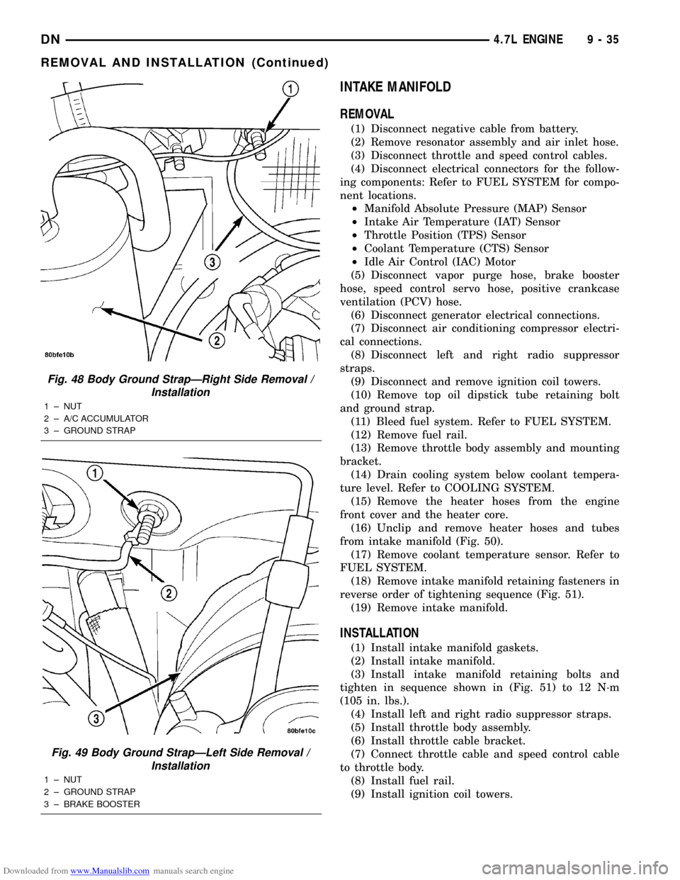
(36) Disconnect body ground strap at the right side
cowl (Fig. 48).
(37) Disconnect body ground strap at the left side
cowl (Fig. 49).
NOTE: It will be necessary to support the transmis-
sion in order to remove the engine.
(38) Position a suitable jack under the transmis-
sion.
(39) Remove engine from the vehicle.
INSTALLATION
(1) Position engine in the vehicle.
Position both the left and right side engine mount
brackets and install the through bolts and nuts.
Tighten nuts to4X2 vehicles95 N´m (70 ft. lbs.).
4X4 vehicles102 N´m (75 ft. lbs.).
Fig. 41 Engine Mount Through Bolt and Nut
Removal / InstallationÐ4X4 Vehicles
1 ± ENGINE MOUNT BRACKET (2)
2 ± THROUGH BOLT (2)
3 ± LOCKNUT AND WASHER (2)
4 ± ENGINE ISOLATOR TO ENGINE MOUNT BRACKET STUD (2)
5 ± LOCKNUT (2)
Fig. 42 Axle Isolator Bracket Removal /
InstallationÐ4X4 Vehicles With Automatic
Transmission
1 ± TRANSMISSION
2 ± AXLE ISOLATOR BRACKET
3 ± FRONT AXLE 4X4 VEHICLES
4 ± BOLTS
5 ± ENGINE
9 - 32 4.7L ENGINEDN
REMOVAL AND INSTALLATION (Continued)
Page 33 of 193
Downloaded from www.Manualslib.com manuals search engine (2)4X4 vehiclesInstall locknuts onto the engine
mount brackets. Tighten locknuts to 41 N´m (30 ft.
lbs.).
(3) Remove jack from under the transmission.
(4) Remove Engine Lifting Fixture Special Tool
8347 (Fig. 47).
(5) Remove Special Tools 8400 Lifting Studs.
(6) Position generator wiring behind the oil dip-
stick tube, then install the oil dipstick tube upper
mounting bolt.
(7) Connect both left and right side body ground
straps.(8) Install power steering pump.
(9) Connect fuel supply line quick connect fitting.
(10) Connect the vacuum lines at the throttle body
and intake manifold.
(11) Connect engine harness at the following
points (Fig. 46) :
²Intake Air Temperature (IAT) Sensor
²Idle Air Control (IAC) Motor
²Fuel Injectors
²Throttle Position (TPS) Switch
²Engine Oil Pressure Switch
²Engine Coolant Temperature (ECT) Sensor
²Manifold Absolute Pressure (MAP) Sensor
²Camshaft Position (CMP) Sensor
²Coil Over Plugs
(12) Position and install heater hoses and tubes
onto intake manifold.
(13) Install the heater hoses onto the heater core
and the engine front cover.
(14) Install generator.
(15) Install A/C condenser, radiator and transmis-
sion oil cooler as an assembly.
(16) Connect radiator upper and lower hoses.
(17) Connect the transmission oil cooler lines to
the radiator.
(18) Install accessory drive belt, fan assembly and
shroud.
(19) Install A/C compressor. Tighten the A/C com-
pressor and generator M10 mounting bolts 40±68N´M
(30±50 ft. lbs.) and the M8 bolts 22±34 N´m (200±300
in. lbs.).
Fig. 43 Crankshaft Position Sensor
1 ± CRANKSHAFT POSITION SENSOR
2 ± CYLINDER HEAD COVER
3 ± CAMSHAFT POSITION SENSOR
4 ± RIGHT SIDE CYLINDER BLOCK
Fig. 44 Crankcase Breather Connection Points
1 ± CRANKCASE BREATHERS
Fig. 45 Heater Hoses and Tubes Removal /
Installation
1 ± HEATER HOSES AND TUBES
2 ± ROUTING/RETAINING CLIPS
DN4.7L ENGINE 9 - 33
REMOVAL AND INSTALLATION (Continued)
Page 35 of 193
Downloaded from www.Manualslib.com manuals search engine INTAKE MANIFOLD
REMOVAL
(1) Disconnect negative cable from battery.
(2) Remove resonator assembly and air inlet hose.
(3) Disconnect throttle and speed control cables.
(4) Disconnect electrical connectors for the follow-
ing components: Refer to FUEL SYSTEM for compo-
nent locations.
²Manifold Absolute Pressure (MAP) Sensor
²Intake Air Temperature (IAT) Sensor
²Throttle Position (TPS) Sensor
²Coolant Temperature (CTS) Sensor
²Idle Air Control (IAC) Motor
(5) Disconnect vapor purge hose, brake booster
hose, speed control servo hose, positive crankcase
ventilation (PCV) hose.
(6) Disconnect generator electrical connections.
(7) Disconnect air conditioning compressor electri-
cal connections.
(8) Disconnect left and right radio suppressor
straps.
(9) Disconnect and remove ignition coil towers.
(10) Remove top oil dipstick tube retaining bolt
and ground strap.
(11) Bleed fuel system. Refer to FUEL SYSTEM.
(12) Remove fuel rail.
(13) Remove throttle body assembly and mounting
bracket.
(14) Drain cooling system below coolant tempera-
ture level. Refer to COOLING SYSTEM.
(15) Remove the heater hoses from the engine
front cover and the heater core.
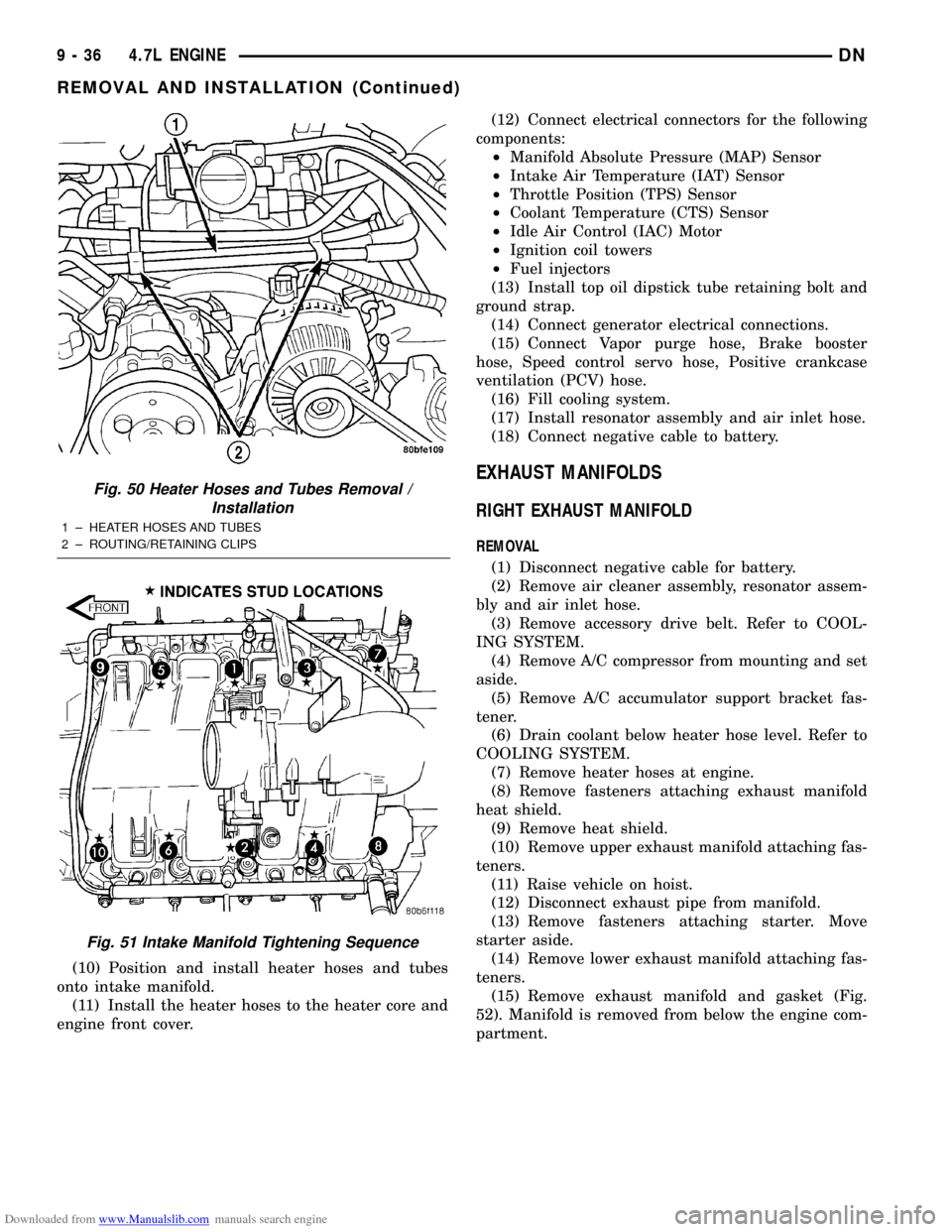
(16) Unclip and remove heater hoses and tubes
from intake manifold (Fig. 50).
(17) Remove coolant temperature sensor. Refer to
FUEL SYSTEM.
(18) Remove intake manifold retaining fasteners in
reverse order of tightening sequence (Fig. 51).
(19) Remove intake manifold.
INSTALLATION
(1) Install intake manifold gaskets.
(2) Install intake manifold.
(3) Install intake manifold retaining bolts and
tighten in sequence shown in (Fig. 51) to 12 N´m
(105 in. lbs.).
(4) Install left and right radio suppressor straps.
(5) Install throttle body assembly.
(6) Install throttle cable bracket.
(7) Connect throttle cable and speed control cable
to throttle body.
(8) Install fuel rail.
(9) Install ignition coil towers.
Fig. 48 Body Ground StrapÐRight Side Removal /
Installation
1 ± NUT
2 ± A/C ACCUMULATOR
3 ± GROUND STRAP
Fig. 49 Body Ground StrapÐLeft Side Removal /
Installation
1 ± NUT
2 ± GROUND STRAP
3 ± BRAKE BOOSTER
DN4.7L ENGINE 9 - 35
REMOVAL AND INSTALLATION (Continued)
Page 36 of 193
Downloaded from www.Manualslib.com manuals search engine (10) Position and install heater hoses and tubes
onto intake manifold.
(11) Install the heater hoses to the heater core and
engine front cover.(12) Connect electrical connectors for the following
components:
²Manifold Absolute Pressure (MAP) Sensor
²Intake Air Temperature (IAT) Sensor
²Throttle Position (TPS) Sensor
²Coolant Temperature (CTS) Sensor
²Idle Air Control (IAC) Motor
²Ignition coil towers
²Fuel injectors
(13) Install top oil dipstick tube retaining bolt and
ground strap.
(14) Connect generator electrical connections.
(15) Connect Vapor purge hose, Brake booster
hose, Speed control servo hose, Positive crankcase
ventilation (PCV) hose.
(16) Fill cooling system.
(17) Install resonator assembly and air inlet hose.
(18) Connect negative cable to battery.
EXHAUST MANIFOLDS
RIGHT EXHAUST MANIFOLD
REMOVAL
(1) Disconnect negative cable for battery.
(2) Remove air cleaner assembly, resonator assem-
bly and air inlet hose.
(3) Remove accessory drive belt. Refer to COOL-
ING SYSTEM.
(4) Remove A/C compressor from mounting and set
aside.
(5) Remove A/C accumulator support bracket fas-
tener.
(6) Drain coolant below heater hose level. Refer to
COOLING SYSTEM.
(7) Remove heater hoses at engine.
(8) Remove fasteners attaching exhaust manifold
heat shield.
(9) Remove heat shield.
(10) Remove upper exhaust manifold attaching fas-
teners.
(11) Raise vehicle on hoist.
(12) Disconnect exhaust pipe from manifold.
(13) Remove fasteners attaching starter. Move
starter aside.
(14) Remove lower exhaust manifold attaching fas-
teners.
(15) Remove exhaust manifold and gasket (Fig.
52). Manifold is removed from below the engine com-
partment.
Fig. 50 Heater Hoses and Tubes Removal /
Installation
1 ± HEATER HOSES AND TUBES
2 ± ROUTING/RETAINING CLIPS
Fig. 51 Intake Manifold Tightening Sequence
9 - 36 4.7L ENGINEDN
REMOVAL AND INSTALLATION (Continued)
Page 92 of 193

Downloaded from www.Manualslib.com manuals search engine Scrape or wire brush all gasket surfaces to remove
all loose material. Inspect stamped parts to ensure
gasket rails are flat. Flatten rails with a hammer on
a flat plate, if required. Gasket surfaces must be free
of oil and dirt. Make sure the old gasket material is
removed from blind attaching holes.
GASKET APPLICATION
Assembling parts using a form-in-place gasket
requires care.
Mopar Silicone Rubber Adhesive Sealant should be
applied in a continuous bead approximately 3 mm
(0.12 inch) in diameter. All mounting holes must be
circled. For corner sealing,a3or6mm(1/8 or 1/4
inch) drop is placed in the center of the gasket con-
tact area. Uncured sealant may be removed with a
shop towel. Components should be torqued in place
while the sealant is still wet to the touch (within 10
minutes). The use of a locating dowel is recom-
mended during assembly to prevent smearing the
material off location.
Mopar Gasket Maker should be applied sparingly
to one gasket surface. The sealant diameter should
be 1.00 mm (0.04 inch) or less. Be certain the mate-
rial surrounds each mounting hole. Excess material
can easily be wiped off. Components should be
torqued in place within 15 minutes. The use of a
locating dowel is recommended during assembly to
prevent smearing the material off location.
ENGINE PERFORMANCE
It is important that the vehicle is operating to its
optimum performance level to maintain fuel economy
and the lowest emission levels. If vehicle is not oper-
ating to these standards, refer to Engine Diagnosis
outlined in this section. The following procedures can
assist in achieving the proper engine diagnosis.
(1) Test cranking amperage draw. Refer to Electri-
cal Group 8B, Cold Cranking Test.
(2) Check intake manifold bolt torque.
(3) Perform cylinder compression test. Refer to
Cylinder Compression Pressure Test in the Engine
Diagnosis area of this section.
(4) Clean or replace spark plugs as necessary and
adjust gap as specified in Electrical Group 8D.
Tighten to specifications.
(5) Test resistance of spark plug cables. Refer to
Electrical Group 8D, Spark Plug Cables.
(6) Inspect the primary wires. Test coil output volt-
age and primary resistance. Replace parts as neces-
sary. Refer to Electrical Group 8D, for specifications.
(7) Test fuel pump for pressure. Refer to Group 14,
Fuel System Specifications.
(8) The air filter elements should be replaced as
specified in Lubrication and Maintenance, Group 0.(9) Inspect crankcase ventilation system as out
lined in Group 0, Lubrication and Maintenance. For
emission controls see Group 25, Emission Controls
for service procedures.
(10) Road test vehicle as a final test.
ENGINE OIL
WARNING: NEW OR USED ENGINE OIL CAN BE
IRRITATING TO THE SKIN. AVOID PROLONGED OR
REPEATED SKIN CONTACT WITH ENGINE OIL.
CONTAMINANTS IN USED ENGINE OIL, CAUSED BY
INTERNAL COMBUSTION, CAN BE HAZARDOUS TO
YOUR HEALTH. THOROUGHLY WASH EXPOSED
SKIN WITH SOAP AND WATER. DO NOT WASH
SKIN WITH GASOLINE, DIESEL FUEL, THINNER, OR
SOLVENTS, HEALTH PROBLEMS CAN RESULT. DO
NOT POLLUTE, DISPOSE OF USED ENGINE OIL
PROPERLY.
ENGINE OIL SPECIFICATION
CAUTION: Do not use non-detergent or straight
mineral oil when adding or changing crankcase
lubricant. Engine failure can result.
API SERVICE GRADE CERTIFIED
In gasoline engines, use an engine oil that is API
Service Grade Certified (Fig. 11). Standard engine oil
identification notations have been adopted to aid in
the proper selection of engine oil. The identifying
notations are located on the label of engine oil plastic
bottles and the top of engine oil cans. MOPAR only
provides engine oil that conforms to this certification.
SAE VISCOSITY
An SAE viscosity grade is used to specify the vis-
cosity of engine oil. SAE 10W-30 specifies a multiple
viscosity engine oil. These are specified with a dual
SAE viscosity grade which indicates the cold-to-hot
temperature viscosity range. When choosing an
engine oil, consider the range of temperatures the
vehicle will be operated in before the next oil change.
Select an engine oil that is best suited to your area's
Fig. 11 Engine Oil Container Standard Notations
9 - 92 5.2L ENGINEDN
SERVICE PROCEDURES (Continued)
Page 93 of 193
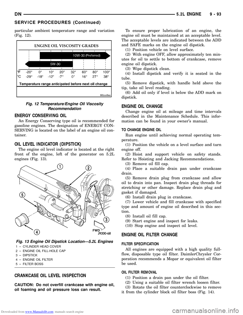
Downloaded from www.Manualslib.com manuals search engine particular ambient temperature range and variation
(Fig. 12).
ENERGY CONSERVING OIL
An Energy Conserving type oil is recommended for
gasoline engines. The designation of ENERGY CON-
SERVING is located on the label of an engine oil con-
tainer.
OIL LEVEL INDICATOR (DIPSTICK)
The engine oil level indicator is located at the right
front of the engine, left of the generator on 5.2L
engines (Fig. 13).
CRANKCASE OIL LEVEL INSPECTION
CAUTION: Do not overfill crankcase with engine oil,
oil foaming and oil pressure loss can result.To ensure proper lubrication of an engine, the
engine oil must be maintained at an acceptable level.
The acceptable levels are indicated between the ADD
and SAFE marks on the engine oil dipstick.
(1) Position vehicle on level surface.
(2) With engine OFF, allow approximately ten min-
utes for oil to settle to bottom of crankcase, remove
engine oil dipstick.
(3) Wipe dipstick clean.
(4) Install dipstick and verify it is seated in the
tube.
(5) Remove dipstick, with handle held above the
tip, take oil level reading.
(6) Add oil only if level is below the ADD mark on
dipstick.
ENGINE OIL CHANGE
Change engine oil at mileage and time intervals
described in the Maintenance Schedule. This infor-
mation can be found in your owner's manual.
TO CHANGE ENGINE OIL
Run engine until achieving normal operating tem-
perature.
(1) Position the vehicle on a level surface and turn
engine off.
(2) Hoist and support vehicle on safety stands.
Refer to Hoisting and Jacking Recommendations.
(3) Remove oil fill cap.
(4) Place a suitable drain pan under crankcase
drain.
(5) Remove drain plug from crankcase and allow
oil to drain into pan. Inspect drain plug threads for
stretching or other damage. Replace drain plug and
gasket if damaged.
(6) Install drain plug in crankcase.
(7) Lower vehicle and fill crankcase with specified
type and amount of engine oil described in this sec-
tion.
(8) Install oil fill cap.
(9) Start engine and inspect for leaks.
(10) Stop engine and inspect oil level.
ENGINE OIL FILTER CHANGE
FILTER SPECIFICATION
All engines are equipped with a high quality full-
flow, disposable type oil filter. DaimlerChrysler Cor-
poration recommends a Mopar or equivalent oil filter
be used.
OIL FILTER REMOVAL
(1) Position a drain pan under the oil filter.
(2) Using a suitable oil filter wrench loosen filter.
(3) Rotate the oil filter counterclockwise to remove
it from the cylinder block oil filter boss (Fig. 14).
Fig. 12 Temperature/Engine Oil Viscosity
Recommendation
Fig. 13 Engine Oil Dipstick LocationÐ5.2L Engines
1 ± CYLINDER HEAD COVER
2 ± ENGINE OIL FILL-HOLE CAP
3 ± DIPSTICK
4 ± ENGINE OIL FILTER
5 ± FILTER BOSS
DN5.2L ENGINE 9 - 93
SERVICE PROCEDURES (Continued)