height DODGE DURANGO 1998 1.G User Guide
[x] Cancel search | Manufacturer: DODGE, Model Year: 1998, Model line: DURANGO, Model: DODGE DURANGO 1998 1.GPages: 193, PDF Size: 5.65 MB
Page 126 of 193
Downloaded from www.Manualslib.com manuals search engine Clean oil pan in solvent and wipe dry with a clean
cloth.
Clean oil screen and pipe thoroughly in clean sol-
vent. Inspect condition of screen.
INSPECTION
Inspect oil drain plug and plug hole for stripped or
damaged threads. Repair as necessary.
Inspect oil pan mounting flange for bends or distor-
tion. Straighten flange, if necessary.
OIL PUMP
INSPECTION
Mating surface of the oil pump cover should be
smooth. Replace pump assembly if cover is scratched
or grooved.
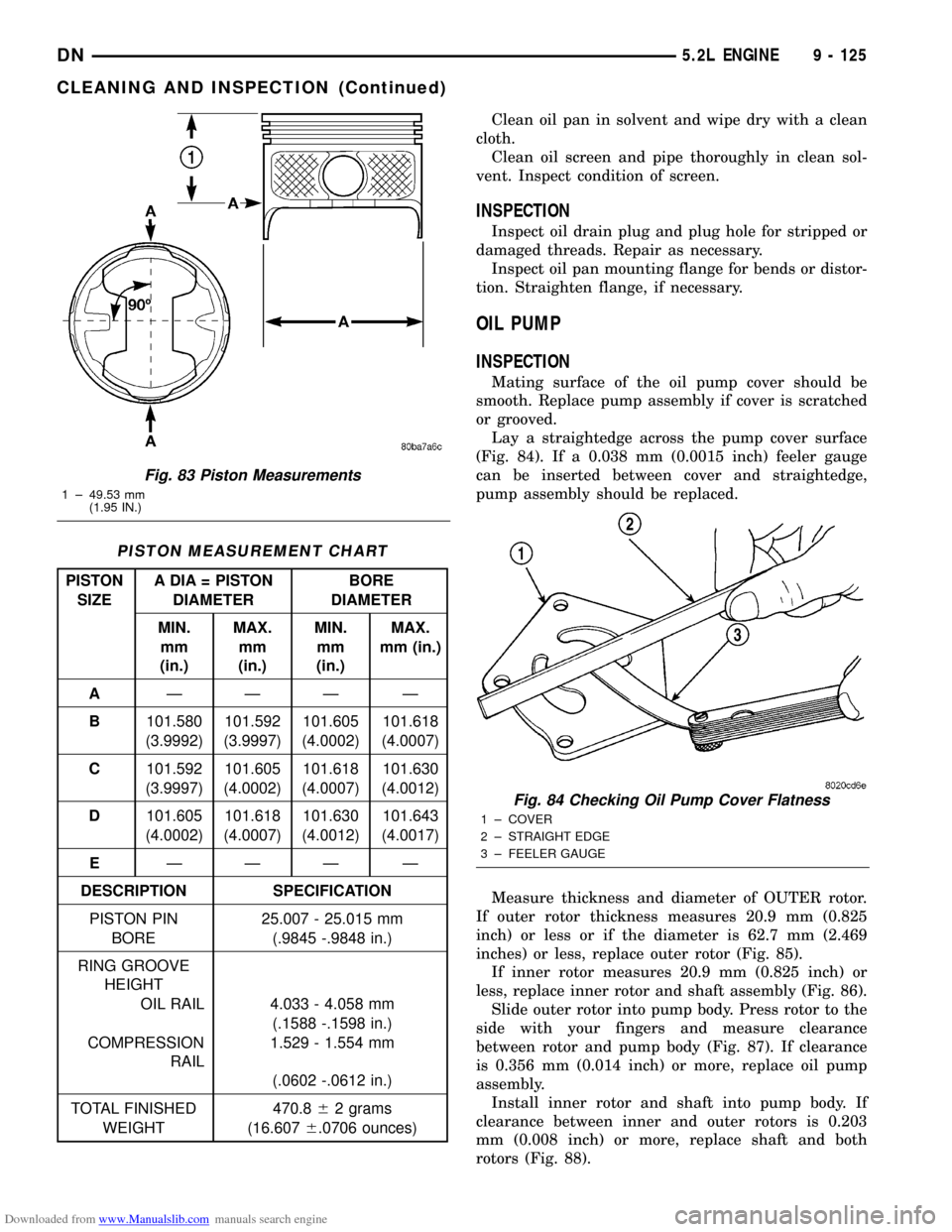
Lay a straightedge across the pump cover surface
(Fig. 84). If a 0.038 mm (0.0015 inch) feeler gauge
can be inserted between cover and straightedge,
pump assembly should be replaced.
Measure thickness and diameter of OUTER rotor.
If outer rotor thickness measures 20.9 mm (0.825
inch) or less or if the diameter is 62.7 mm (2.469
inches) or less, replace outer rotor (Fig. 85).
If inner rotor measures 20.9 mm (0.825 inch) or
less, replace inner rotor and shaft assembly (Fig. 86).
Slide outer rotor into pump body. Press rotor to the
side with your fingers and measure clearance
between rotor and pump body (Fig. 87). If clearance
is 0.356 mm (0.014 inch) or more, replace oil pump
assembly.
Install inner rotor and shaft into pump body. If
clearance between inner and outer rotors is 0.203
mm (0.008 inch) or more, replace shaft and both
rotors (Fig. 88).
Fig. 83 Piston Measurements
1 ± 49.53 mm
(1.95 IN.)
PISTON MEASUREMENT CHART
PISTON A DIA = PISTON BORE
SIZE DIAMETER DIAMETER
MIN. MAX. MIN. MAX.
mm
(in.)mm
(in.)mm
(in.)mm (in.)
AÐÐÐ Ð
B101.580 101.592 101.605 101.618
(3.9992) (3.9997) (4.0002) (4.0007)
C101.592 101.605 101.618 101.630
(3.9997) (4.0002) (4.0007) (4.0012)
D101.605 101.618 101.630 101.643
(4.0002) (4.0007) (4.0012) (4.0017)
EÐÐÐ Ð
DESCRIPTION SPECIFICATION
PISTON PIN 25.007 - 25.015 mm
BORE (.9845 -.9848 in.)
RING GROOVE
HEIGHT
OIL RAIL 4.033 - 4.058 mm
(.1588 -.1598 in.)
COMPRESSION
RAIL1.529 - 1.554 mm
(.0602 -.0612 in.)
TOTAL FINISHED 470.862 grams
WEIGHT (16.6076.0706 ounces)
Fig. 84 Checking Oil Pump Cover Flatness
1 ± COVER
2 ± STRAIGHT EDGE
3 ± FEELER GAUGE
DN5.2L ENGINE 9 - 125
CLEANING AND INSPECTION (Continued)
Page 131 of 193
Downloaded from www.Manualslib.com manuals search engine DESCRIPTION SPECIFICATION
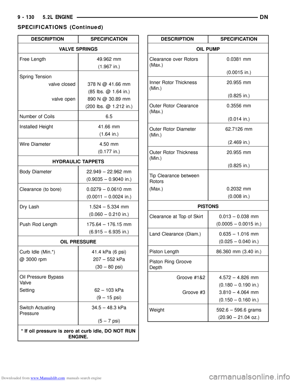
VALVE SPRINGS
Free Length 49.962 mm
(1.967 in.)
Spring Tension
valve closed 378 N @ 41.66 mm
(85 lbs. @ 1.64 in.)
valve open 890 N @ 30.89 mm
(200 lbs. @ 1.212 in.)
Number of Coils 6.5
Installed Height 41.66 mm
(1.64 in.)
Wire Diameter 4.50 mm
(0.177 in.)
HYDRAULIC TAPPETS
Body Diameter 22.949 ± 22.962 mm
(0.9035 ± 0.9040 in.)
Clearance (to bore) 0.0279 ± 0.0610 mm
(0.0011 ± 0.0024 in.)
Dry Lash 1.524 ± 5.334 mm
(0.060 ± 0.210 in.)
Push Rod Length 175.64 ± 176.15 mm
(6.915 ± 6.935 in.)
OIL PRESSURE
Curb Idle (Min.*) 41.4 kPa (6 psi)
@ 3000 rpm 207 ± 552 kPa
(30 ± 80 psi)
Oil Pressure Bypass
Valve
Setting 62 ± 103 kPa
(9 ± 15 psi)
Switch Actuating
Pressure34.5 ± 48.3 kPa
(5 ± 7 psi)
* If oil pressure is zero at curb idle, DO NOT RUN
ENGINE.DESCRIPTION SPECIFICATION
OIL PUMP
Clearance over Rotors
(Max.)0.0381 mm
(0.0015 in.)
Inner Rotor Thickness
(Min.)20.955 mm
(0.825 in.)
Outer Rotor Clearance
(Max.)0.3556 mm
(0.014 in.)
Outer Rotor Diameter
(Min.)62.7126 mm
(2.469 in.)
Outer Rotor Thickness
(Min.)20.955 mm
(0.825 in.)
Tip Clearance between
Rotors
(Max.) 0.2032 mm
(0.008 in.)
PISTONS
Clearance at Top of Skirt 0.013 ± 0.038 mm
(0.0005 ± 0.0015 in.)
Land Clearance (Diam.) 0.635 ± 1.016 mm
(0.025 ± 0.040 in.)
Piston Length 86.360 mm (3.40 in.)
Piston Ring Groove
Depth
Groove #1&2 4.572 ± 4.826 mm
(0.180 ± 0.190 in.)
Groove #3 3.810 ± 4.064 mm
(0.150 ± 0.160 in.)
Weight 592.6 ± 596.6 grams
(20.90 ± 21.04 oz.)
9 - 130 5.2L ENGINEDN
SPECIFICATIONS (Continued)
Page 154 of 193
Downloaded from www.Manualslib.com manuals search engine (6) Identify the fluid in the cylinders (i.e. coolant,
fuel, oil, etc.).
(7) Make sure all fluid has been removed from the
cylinders.
(8) Repair engine or components as necessary to
prevent this problem from occurring again.
(9) Squirt engine oil into the cylinders to lubricate
the walls. This will prevent damage on restart.
(10) Install new spark plugs.
(11) Drain engine oil. Remove and discard the oil
filter.
(12) Install the drain plug. Tighten the plug to 34
N´m (25 ft. lbs.) torque.
(13) Install a new oil filter.
(14) Fill engine crankcase with the specified
amount and grade of oil.
(15) Connect the negative cable to the battery.
(16) Start the engine and check for any leaks.
VALVE TIMING
(1) Turn crankshaft until the No.6 exhaust valve is
closing and No.6 intake valve is opening.
(2) Insert a 6.350 mm (1/4 inch) spacer between
rocker arm pad and stem tip of No.1 intake valve.
Allow spring load to bleed tappet down giving in
effect a solid tappet.
(3) Install a dial indicator so plunger contacts
valve spring retainer as nearly perpendicular as pos-
sible. Zero the indicator.
(4) Rotate the crankshaft clockwise (normal run-
ning direction) until the valve has lifted 0.863 mm
(0.034 inch). The timing of the crankshaft should
now read from 10É before top dead center to 2É after
top dead center. Remove spacer.
CAUTION: DO NOT turn crankshaft any further
clockwise as valve spring might bottom and result
in serious damage.
If reading is not within specified limits:
²Check sprocket index marks.
²Inspect timing chain for wear.
²Check accuracy of DC mark on timing indicator.
VALVE SERVICE
VALVE CLEANING
Clean valves thoroughly. Discard burned, warped
and cracked valves.
Remove carbon and varnish deposits from inside of
valve guides with a reliable guide cleaner.
VALVE INSPECTION
Measure valve stems for wear. If wear exceeds
0.051 mm (0.002 inch), replace the valve.
VALVE GUIDES
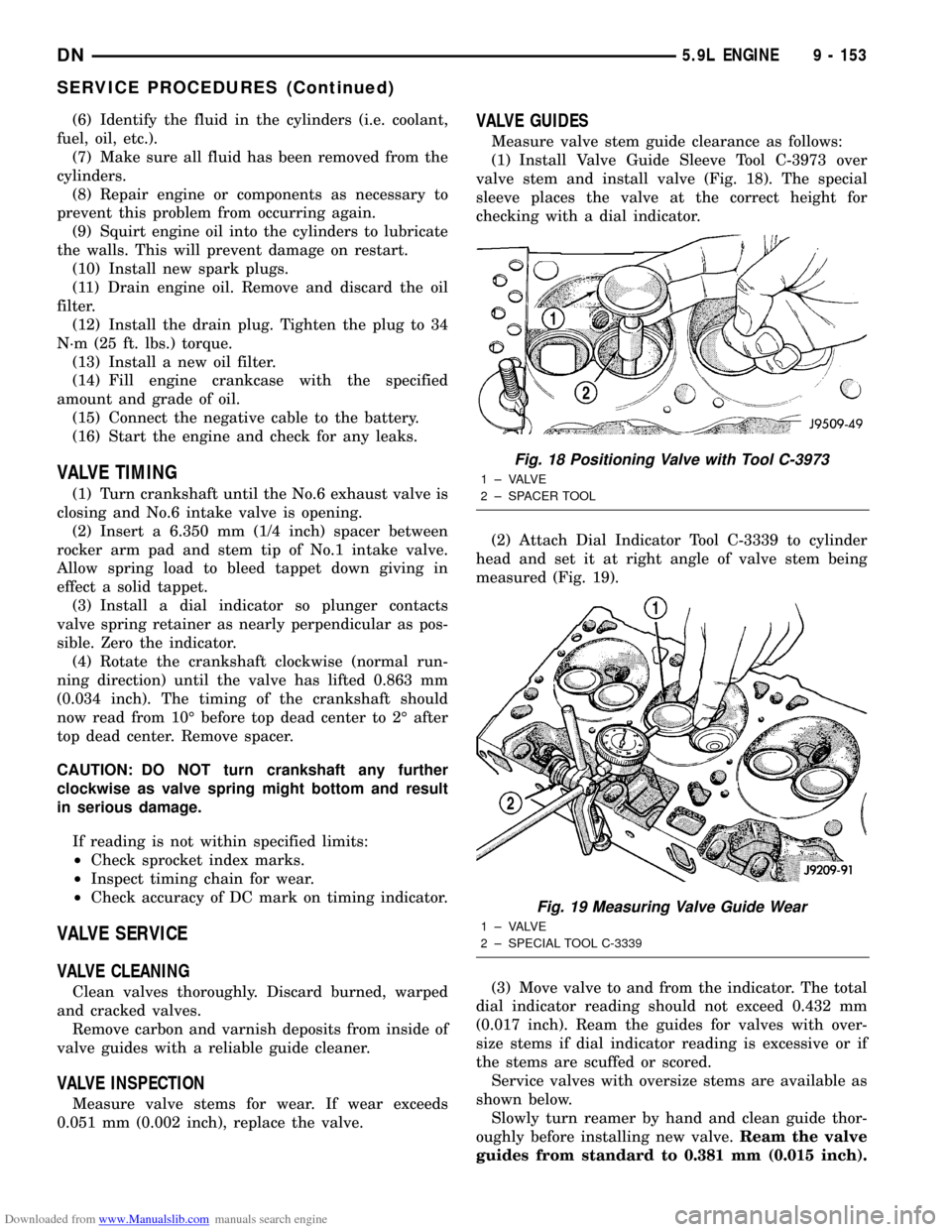
Measure valve stem guide clearance as follows:
(1) Install Valve Guide Sleeve Tool C-3973 over
valve stem and install valve (Fig. 18). The special
sleeve places the valve at the correct height for
checking with a dial indicator.
(2) Attach Dial Indicator Tool C-3339 to cylinder
head and set it at right angle of valve stem being
measured (Fig. 19).
(3) Move valve to and from the indicator. The total
dial indicator reading should not exceed 0.432 mm
(0.017 inch). Ream the guides for valves with over-
size stems if dial indicator reading is excessive or if
the stems are scuffed or scored.
Service valves with oversize stems are available as
shown below.
Slowly turn reamer by hand and clean guide thor-
oughly before installing new valve.Ream the valve
guides from standard to 0.381 mm (0.015 inch).
Fig. 18 Positioning Valve with Tool C-3973
1 ± VALVE
2 ± SPACER TOOL
Fig. 19 Measuring Valve Guide Wear
1 ± VALVE
2 ± SPECIAL TOOL C-3339
DN5.9L ENGINE 9 - 153
SERVICE PROCEDURES (Continued)
Page 156 of 193
Downloaded from www.Manualslib.com manuals search engine inch). The width of the exhaust seats should be
1.524-2.032 mm (0.060-0.080 inch).
VALVE SPRING INSPECTION
Whenever valves have been removed for inspection,
reconditioning or replacement, valve springs should
be tested. As an example the compression length of
the spring to be tested is 1-5/16 inch. Turn table of
Universal Valve Spring Tester Tool until surface is in
line with the 1-5/16 inch mark on the threaded stud.
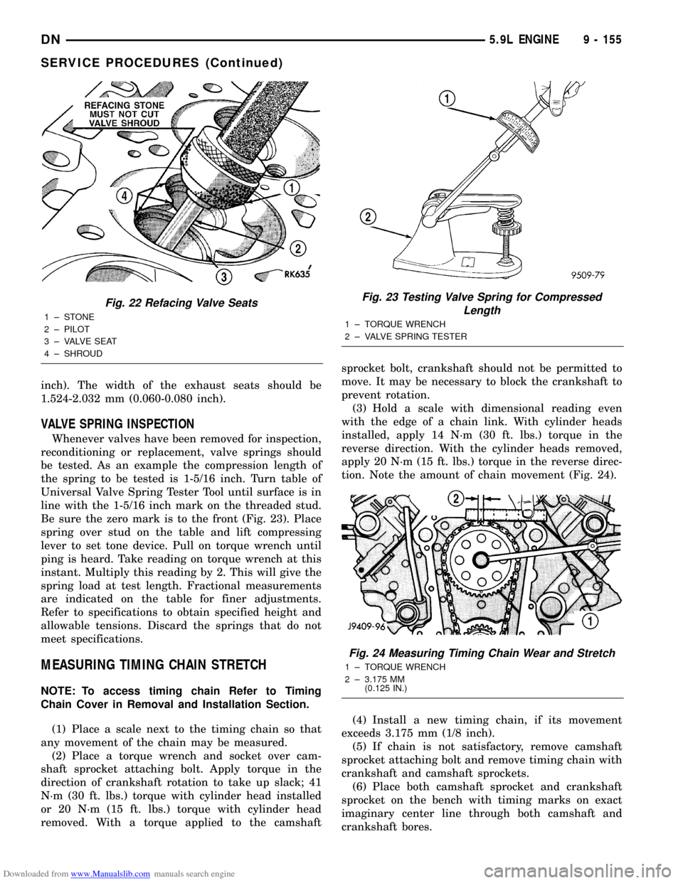
Be sure the zero mark is to the front (Fig. 23). Place
spring over stud on the table and lift compressing
lever to set tone device. Pull on torque wrench until
ping is heard. Take reading on torque wrench at this
instant. Multiply this reading by 2. This will give the
spring load at test length. Fractional measurements
are indicated on the table for finer adjustments.
Refer to specifications to obtain specified height and
allowable tensions. Discard the springs that do not
meet specifications.
MEASURING TIMING CHAIN STRETCH
NOTE: To access timing chain Refer to Timing
Chain Cover in Removal and Installation Section.
(1) Place a scale next to the timing chain so that
any movement of the chain may be measured.
(2) Place a torque wrench and socket over cam-
shaft sprocket attaching bolt. Apply torque in the
direction of crankshaft rotation to take up slack; 41
N´m (30 ft. lbs.) torque with cylinder head installed
or 20 N´m (15 ft. lbs.) torque with cylinder head
removed. With a torque applied to the camshaftsprocket bolt, crankshaft should not be permitted to
move. It may be necessary to block the crankshaft to
prevent rotation.
(3) Hold a scale with dimensional reading even
with the edge of a chain link. With cylinder heads
installed, apply 14 N´m (30 ft. lbs.) torque in the
reverse direction. With the cylinder heads removed,
apply 20 N´m (15 ft. lbs.) torque in the reverse direc-
tion. Note the amount of chain movement (Fig. 24).
(4) Install a new timing chain, if its movement
exceeds 3.175 mm (1/8 inch).
(5) If chain is not satisfactory, remove camshaft
sprocket attaching bolt and remove timing chain with
crankshaft and camshaft sprockets.
(6) Place both camshaft sprocket and crankshaft
sprocket on the bench with timing marks on exact
imaginary center line through both camshaft and
crankshaft bores.
Fig. 22 Refacing Valve Seats
1±STONE
2 ± PILOT
3 ± VALVE SEAT
4 ± SHROUD
Fig. 23 Testing Valve Spring for Compressed
Length
1 ± TORQUE WRENCH
2 ± VALVE SPRING TESTER
Fig. 24 Measuring Timing Chain Wear and Stretch
1 ± TORQUE WRENCH
2 ± 3.175 MM
(0.125 IN.)
DN5.9L ENGINE 9 - 155
SERVICE PROCEDURES (Continued)
Page 158 of 193
Downloaded from www.Manualslib.com manuals search engine CONNECTING ROD BEARINGSÐFITTING
Fit all rods on a bank until completed. DO NOT
alternate from one bank to another, because connect-
ing rods and pistons are not interchangeable from
one bank to another.
The bearing caps are not interchangeable and
should be marked at removal to ensure correct
assembly.
Each bearing cap has a small V-groove across the
parting face. When installing the lower bearing shell,
make certain that the V-groove in the shell is in line
with the V-groove in the cap. This provides lubrica-
tion of the cylinder wall in the opposite bank.The bearing shells must be installed so that the
tangs are in the machined grooves in the rods and
caps.
Limits of taper or out-of-round on any crankshaft
journals should be held to 0.025 mm (0.001 inch).
Bearings are available in 0.025 mm (0.001 inch),
0.051 mm (0.002 inch), 0.076 mm (0.003 inch), 0.254
mm (0.010 inch) and 0.305 mm (0.012 inch) under-
size.Install the bearings in pairs. DO NOT use a
new bearing half with an old bearing half. DO
NOT file the rods or bearing caps.
CRANKSHAFT MAIN BEARINGSÐFITTING
Bearing caps are not interchangeable and should
be marked at removal to ensure correct assembly.
Upper and lower bearing halves are NOT inter-
changeable. Lower main bearing halves of No.2 and 4
are interchangeable.
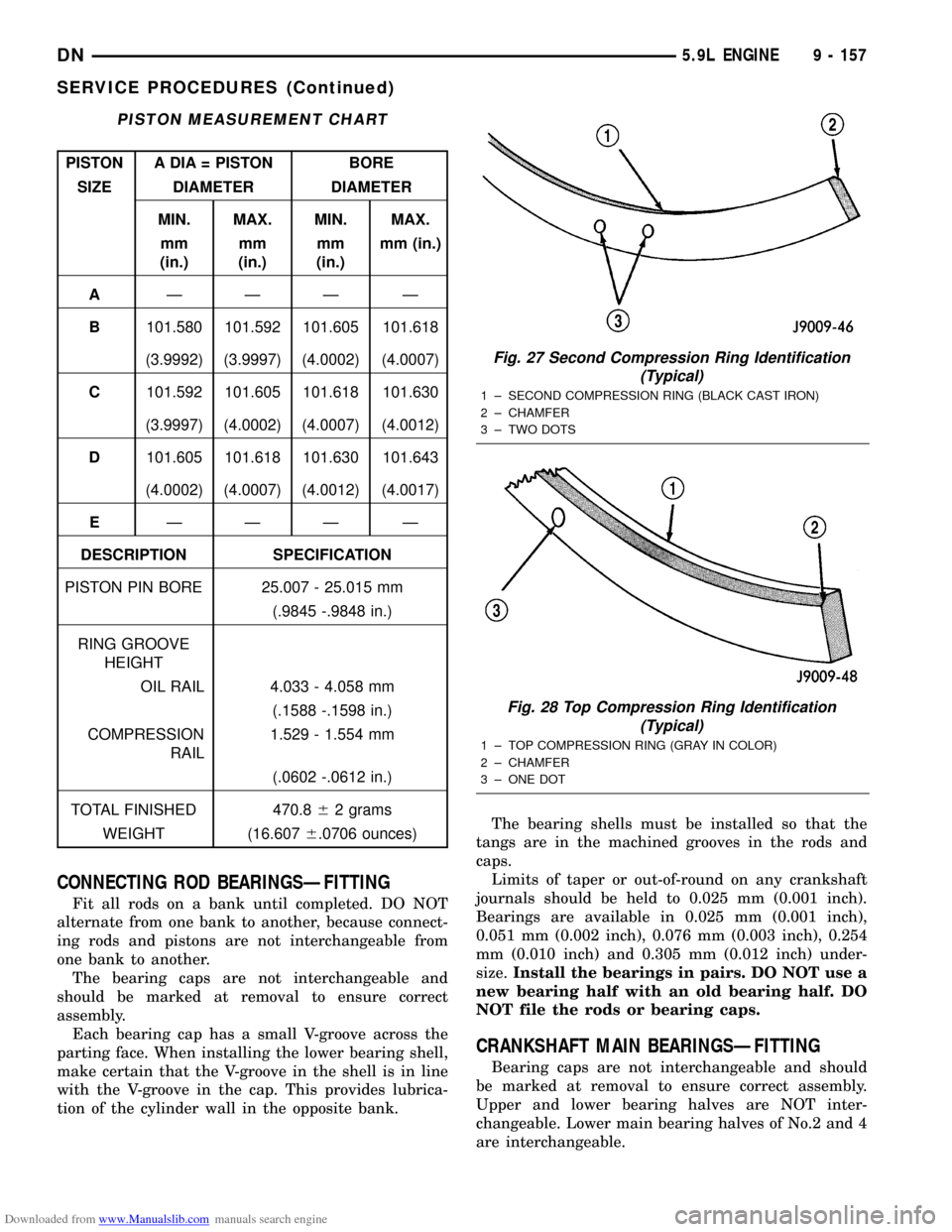
PISTON MEASUREMENT CHART
PISTON A DIA = PISTON BORE
SIZE DIAMETER DIAMETER
MIN. MAX. MIN. MAX.
mm
(in.)mm
(in.)mm
(in.)mm (in.)
AÐÐÐ Ð
B101.580 101.592 101.605 101.618
(3.9992) (3.9997) (4.0002) (4.0007)
C101.592 101.605 101.618 101.630
(3.9997) (4.0002) (4.0007) (4.0012)
D101.605 101.618 101.630 101.643
(4.0002) (4.0007) (4.0012) (4.0017)
EÐÐÐ Ð
DESCRIPTION SPECIFICATION
PISTON PIN BORE 25.007 - 25.015 mm
(.9845 -.9848 in.)
RING GROOVE
HEIGHT
OIL RAIL 4.033 - 4.058 mm
(.1588 -.1598 in.)
COMPRESSION
RAIL1.529 - 1.554 mm
(.0602 -.0612 in.)
TOTAL FINISHED 470.862 grams
WEIGHT (16.6076.0706 ounces)
Fig. 27 Second Compression Ring Identification
(Typical)
1 ± SECOND COMPRESSION RING (BLACK CAST IRON)
2 ± CHAMFER
3 ± TWO DOTS
Fig. 28 Top Compression Ring Identification
(Typical)
1 ± TOP COMPRESSION RING (GRAY IN COLOR)
2 ± CHAMFER
3 ± ONE DOT
DN5.9L ENGINE 9 - 157
SERVICE PROCEDURES (Continued)
Page 164 of 193
Downloaded from www.Manualslib.com manuals search engine INTAKE MANIFOLD
REMOVAL
(1) Disconnect the battery negative cable.
(2) Drain the cooling system. Refer to COOLING
SYSTEM.
(3) Remove the A/C compressor. Refer to HEAT-
ING and AIR CONDITIONING.
(4) Remove the generator. Refer to CHARGING
SYSTEM.
(5) Remove the accessory drive bracket.
(6) Remove the air cleaner assembly and air inlet
hose.
(7) Perform the fuel pressure release procedure.
Refer to FUEL SYSTEM.
(8) Disconnect the fuel supply line from the fuel
rail. Refer to FUEL SYSTEM.
(9) Disconnect the accelerator linkage and, if so
equipped, the speed control and transmission kick-
down cables.
(10) Remove the distributor cap and wires.
(11) Disconnect the coil wires.
(12) Disconnect the coolant temperature sending
unit wire.
(13) Disconnect the heater hoses and bypass hose.
(14) Remove the closed crankcase ventilation and
evaporation control systems.
(15) Remove intake manifold bolts.
(16) Lift the intake manifold and throttle body out
of the engine compartment as an assembly.
(17) Remove and discard the flange side gaskets
and the front and rear cross-over gaskets.
(18) Remove the throttle body bolts and lift the
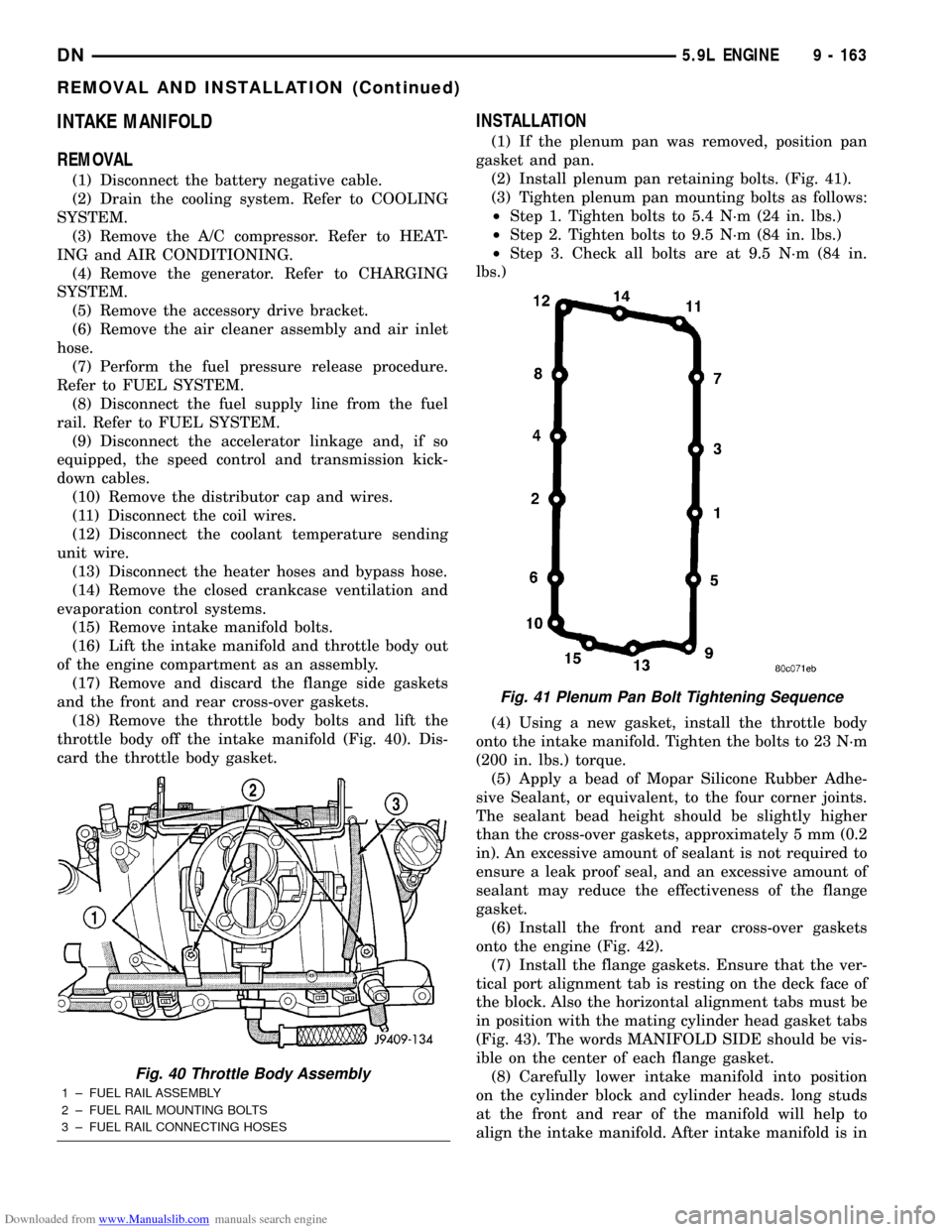
throttle body off the intake manifold (Fig. 40). Dis-
card the throttle body gasket.
INSTALLATION
(1) If the plenum pan was removed, position pan
gasket and pan.
(2) Install plenum pan retaining bolts. (Fig. 41).
(3) Tighten plenum pan mounting bolts as follows:
²Step 1. Tighten bolts to 5.4 N´m (24 in. lbs.)
²Step 2. Tighten bolts to 9.5 N´m (84 in. lbs.)
²Step 3. Check all bolts are at 9.5 N´m (84 in.
lbs.)
(4) Using a new gasket, install the throttle body
onto the intake manifold. Tighten the bolts to 23 N´m
(200 in. lbs.) torque.
(5) Apply a bead of Mopar Silicone Rubber Adhe-
sive Sealant, or equivalent, to the four corner joints.
The sealant bead height should be slightly higher
than the cross-over gaskets, approximately 5 mm (0.2
in). An excessive amount of sealant is not required to
ensure a leak proof seal, and an excessive amount of
sealant may reduce the effectiveness of the flange
gasket.
(6) Install the front and rear cross-over gaskets
onto the engine (Fig. 42).
(7) Install the flange gaskets. Ensure that the ver-
tical port alignment tab is resting on the deck face of
the block. Also the horizontal alignment tabs must be
in position with the mating cylinder head gasket tabs
(Fig. 43). The words MANIFOLD SIDE should be vis-
ible on the center of each flange gasket.
(8) Carefully lower intake manifold into position
on the cylinder block and cylinder heads. long studs
at the front and rear of the manifold will help to
align the intake manifold. After intake manifold is in
Fig. 40 Throttle Body Assembly
1 ± FUEL RAIL ASSEMBLY
2 ± FUEL RAIL MOUNTING BOLTS
3 ± FUEL RAIL CONNECTING HOSES
Fig. 41 Plenum Pan Bolt Tightening Sequence
DN5.9L ENGINE 9 - 163
REMOVAL AND INSTALLATION (Continued)
Page 169 of 193
Downloaded from www.Manualslib.com manuals search engine (4) Before removing valves, remove any burrs from
valve stem lock grooves to prevent damage to the
valve guides. Identify valves to ensure installation in
original location.
INSTALLATION
(1) Coat valve stems with lubrication oil and insert
them in cylinder head.
(2) If valves or seats are reground, check valve
stem height. If valve is too long, replace cylinder
head.
(3) Install new seals on all valve guides. Install
valve springs and valve retainers.
(4) Compress valve springs with Valve Spring
Compressor Tool MD-998772A, install locks and
release tool. If valves and/or seats are ground, mea-
sure the installed height of springs. Make sure the
measurement is taken from bottom of spring seat in
cylinder head to the bottom surface of spring
retainer. If spacers are installed, measure from the
top of spacer. If height is greater than 42.86 mm
(1-11/16 inches), install a 1.587 mm (1/16 inch)
spacer in head counterbore. This should bring spring
height back to normal 41.27 to 42.86 mm (1-5/8 to
1-11/16 inch).
HYDRAULIC TAPPETS
REMOVAL
(1) Remove the air cleaner assembly and air inlet
hose.
(2) Remove cylinder head cover, rocker assembly
and push rods. Identify push rods to ensure installa-
tion in original location.
(3) Remove intake manifold, yoke retainer and
aligning yokes.
(4) Slide Hydraulic Tappet Remover/Installer Tool
C-4129-A through opening in cylinder head and seat
tool firmly in the head of tappet.
(5) Pull tappet out of bore with a twisting motion.
If all tappets are to be removed, identify tappets to
ensure installation in original location.
INSTALLATION
(1) If the tappet or bore in cylinder block is scored,
scuffed, or shows signs of sticking, ream the bore to
next oversize. Replace with oversize tappet.
(2) Lubricate tappets.
(3) Install tappets and push rods in their original
positions. Ensure that the oil feed hole in the side of
the tappet body faces up (away from the crankshaft).
(4) Install aligning yokes with ARROW toward
camshaft.
(5) Install yoke retainer. Tighten the bolts to 23
N´m (200 in. lbs.) torque. Install intake manifold.
(6) Install push rods in original positions.(7) Install rocker arm.
(8) Install cylinder head cover.
(9) Install air cleaner assembly and air inlet hose.
(10) Start and operate engine. Warm up to normal
operating temperature.
CAUTION: To prevent damage to valve mechanism,
engine must not be run above fast idle until all
hydraulic tappets have filled with oil and have
become quiet.
VIBRATION DAMPER
REMOVAL
(1) Disconnect the battery negative cable.
(2) Remove the cooling system fan.
(3) Remove the cooling fan shroud.
(4) Remove the accessory drive belt. Refer to
COOLING SYSTEM.
(5) Remove vibration damper bolt and washer from
end of crankshaft.
(6) Position Special Tool 8513 Insert into the
crankshaft nose.
(7) Install Special Tool 1026 Three Jaw Puller onto
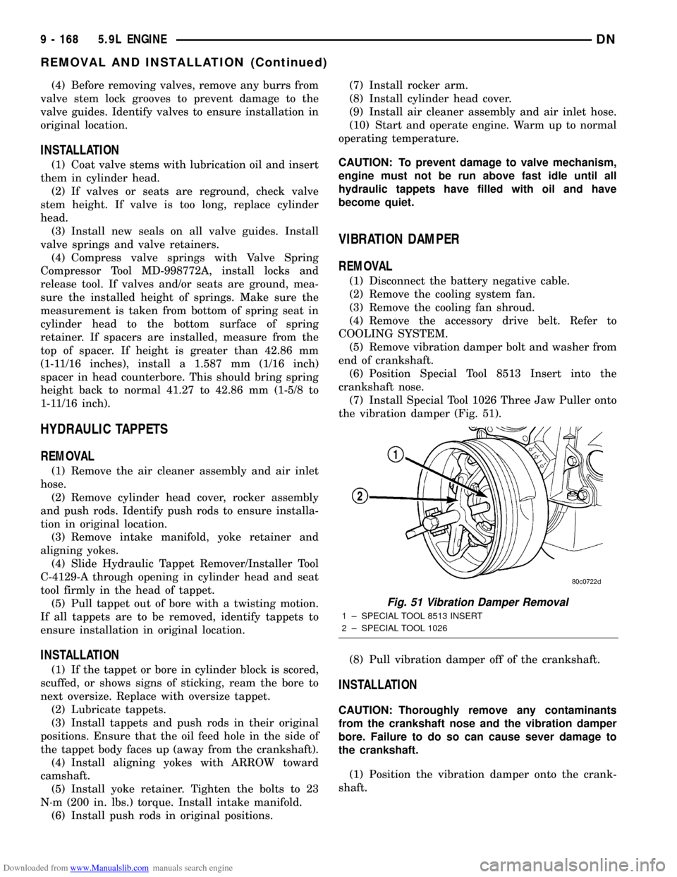
the vibration damper (Fig. 51).
(8) Pull vibration damper off of the crankshaft.
INSTALLATION
CAUTION: Thoroughly remove any contaminants
from the crankshaft nose and the vibration damper
bore. Failure to do so can cause sever damage to
the crankshaft.
(1) Position the vibration damper onto the crank-
shaft.
Fig. 51 Vibration Damper Removal
1 ± SPECIAL TOOL 8513 INSERT
2 ± SPECIAL TOOL 1026
9 - 168 5.9L ENGINEDN
REMOVAL AND INSTALLATION (Continued)
Page 184 of 193
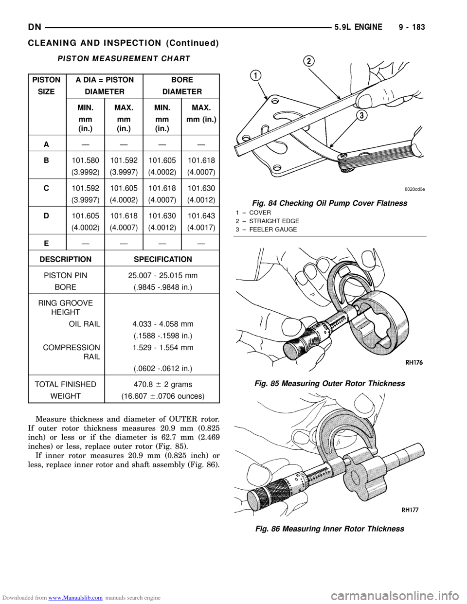
Downloaded from www.Manualslib.com manuals search engine Measure thickness and diameter of OUTER rotor.
If outer rotor thickness measures 20.9 mm (0.825
inch) or less or if the diameter is 62.7 mm (2.469
inches) or less, replace outer rotor (Fig. 85).
If inner rotor measures 20.9 mm (0.825 inch) or
less, replace inner rotor and shaft assembly (Fig. 86).
PISTON MEASUREMENT CHART
PISTON A DIA = PISTON BORE
SIZE DIAMETER DIAMETER
MIN. MAX. MIN. MAX.
mm
(in.)mm
(in.)mm
(in.)mm (in.)
AÐÐÐ Ð
B101.580 101.592 101.605 101.618
(3.9992) (3.9997) (4.0002) (4.0007)
C101.592 101.605 101.618 101.630
(3.9997) (4.0002) (4.0007) (4.0012)
D101.605 101.618 101.630 101.643
(4.0002) (4.0007) (4.0012) (4.0017)
EÐÐÐ Ð
DESCRIPTION SPECIFICATION
PISTON PIN 25.007 - 25.015 mm
BORE (.9845 -.9848 in.)
RING GROOVE
HEIGHT
OIL RAIL 4.033 - 4.058 mm
(.1588 -.1598 in.)
COMPRESSION
RAIL1.529 - 1.554 mm
(.0602 -.0612 in.)
TOTAL FINISHED 470.862 grams
WEIGHT (16.6076.0706 ounces)
Fig. 84 Checking Oil Pump Cover Flatness
1 ± COVER
2 ± STRAIGHT EDGE
3 ± FEELER GAUGE
Fig. 85 Measuring Outer Rotor Thickness
Fig. 86 Measuring Inner Rotor Thickness
DN5.9L ENGINE 9 - 183
CLEANING AND INSPECTION (Continued)
Page 188 of 193
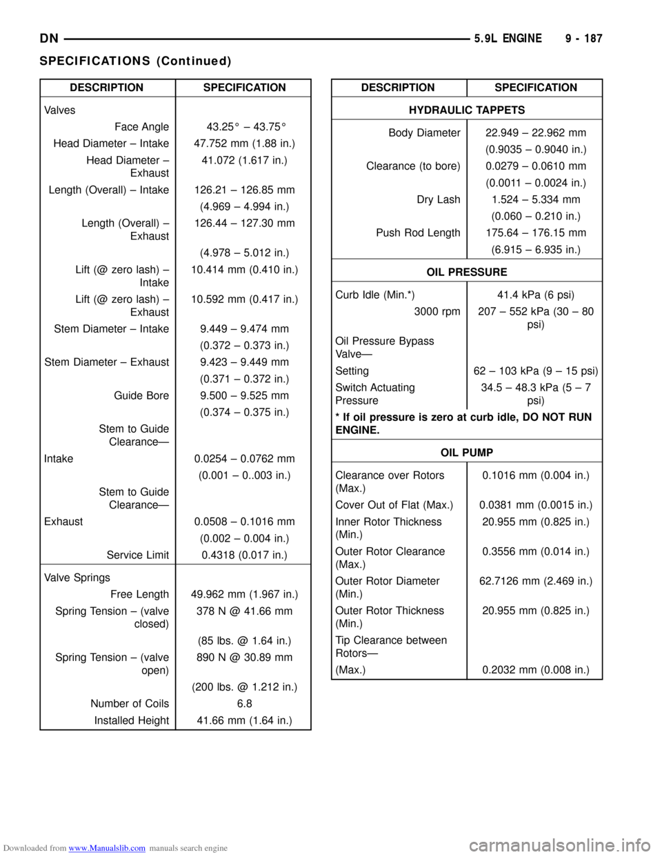
Downloaded from www.Manualslib.com manuals search engine DESCRIPTION SPECIFICATION
Valves
Face Angle 43.25É ± 43.75É
Head Diameter ± Intake 47.752 mm (1.88 in.)
Head Diameter ±
Exhaust41.072 (1.617 in.)
Length (Overall) ± Intake 126.21 ± 126.85 mm
(4.969 ± 4.994 in.)
Length (Overall) ±
Exhaust126.44 ± 127.30 mm
(4.978 ± 5.012 in.)
Lift (@ zero lash) ±
Intake10.414 mm (0.410 in.)
Lift (@ zero lash) ±
Exhaust10.592 mm (0.417 in.)
Stem Diameter ± Intake 9.449 ± 9.474 mm
(0.372 ± 0.373 in.)
Stem Diameter ± Exhaust 9.423 ± 9.449 mm
(0.371 ± 0.372 in.)
Guide Bore 9.500 ± 9.525 mm
(0.374 ± 0.375 in.)
Stem to Guide
ClearanceÐ
Intake 0.0254 ± 0.0762 mm
(0.001 ± 0..003 in.)
Stem to Guide
ClearanceÐ
Exhaust 0.0508 ± 0.1016 mm
(0.002 ± 0.004 in.)
Service Limit 0.4318 (0.017 in.)
Valve Springs
Free Length 49.962 mm (1.967 in.)
Spring Tension ± (valve
closed)378 N @ 41.66 mm
(85 lbs. @ 1.64 in.)
Spring Tension ± (valve
open)890 N @ 30.89 mm
(200 lbs. @ 1.212 in.)
Number of Coils 6.8
Installed Height 41.66 mm (1.64 in.)DESCRIPTION SPECIFICATION
HYDRAULIC TAPPETS
Body Diameter 22.949 ± 22.962 mm
(0.9035 ± 0.9040 in.)
Clearance (to bore) 0.0279 ± 0.0610 mm
(0.0011 ± 0.0024 in.)
Dry Lash 1.524 ± 5.334 mm
(0.060 ± 0.210 in.)
Push Rod Length 175.64 ± 176.15 mm
(6.915 ± 6.935 in.)
OIL PRESSURE
Curb Idle (Min.*) 41.4 kPa (6 psi)
3000 rpm 207 ± 552 kPa (30 ± 80
psi)
Oil Pressure Bypass
ValveÐ
Setting 62 ± 103 kPa (9 ± 15 psi)
Switch Actuating
Pressure34.5 ± 48.3 kPa (5 ± 7
psi)
* If oil pressure is zero at curb idle, DO NOT RUN
ENGINE.
OIL PUMP
Clearance over Rotors
(Max.)0.1016 mm (0.004 in.)
Cover Out of Flat (Max.) 0.0381 mm (0.0015 in.)
Inner Rotor Thickness
(Min.)20.955 mm (0.825 in.)
Outer Rotor Clearance
(Max.)0.3556 mm (0.014 in.)
Outer Rotor Diameter
(Min.)62.7126 mm (2.469 in.)
Outer Rotor Thickness
(Min.)20.955 mm (0.825 in.)
Tip Clearance between
RotorsÐ
(Max.) 0.2032 mm (0.008 in.)
DN5.9L ENGINE 9 - 187
SPECIFICATIONS (Continued)