service DODGE DURANGO 1998 1.G Owner's Manual
[x] Cancel search | Manufacturer: DODGE, Model Year: 1998, Model line: DURANGO, Model: DODGE DURANGO 1998 1.GPages: 193, PDF Size: 5.65 MB
Page 26 of 193
Downloaded from www.Manualslib.com manuals search engine (5) Install bearing cap and connecting rod on the
journal and tighten bolts to 27 N´m (20 ft. lbs.) plus a
90É turn. DO NOT rotate crankshaft. Plastigage will
smear, resulting in inaccurate indication.
(6) Remove the bearing cap and determine amount
of bearing-to-journal clearance by measuring the
width of compressed Plastigage (Fig. 29). Refer to
Engine Specifications for the proper clearance.Plas-
tigage should indicate the same clearance
across the entire width of the insert. If the
clearance varies, it may be caused by either a
tapered journal, bent connecting rod or foreign
material trapped between the insert and cap or
rod.
(7) If the correct clearance is indicated, replace-
ment of the bearing inserts is not necessary. Remove
the Plastigage from crankshaft journal and bearing
insert. Proceed with installation.
(8) If bearing-to-journal clearance exceeds the
specification, determin which services bearing set to
use the bearing sizes are as follows:
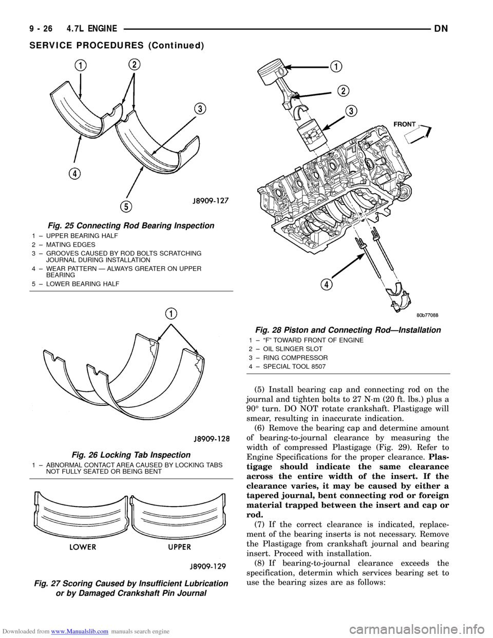
Fig. 25 Connecting Rod Bearing Inspection
1 ± UPPER BEARING HALF
2 ± MATING EDGES
3 ± GROOVES CAUSED BY ROD BOLTS SCRATCHING
JOURNAL DURING INSTALLATION
4 ± WEAR PATTERN Ð ALWAYS GREATER ON UPPER
BEARING
5 ± LOWER BEARING HALF
Fig. 26 Locking Tab Inspection
1 ± ABNORMAL CONTACT AREA CAUSED BY LOCKING TABS
NOT FULLY SEATED OR BEING BENT
Fig. 27 Scoring Caused by Insufficient Lubrication
or by Damaged Crankshaft Pin Journal
Fig. 28 Piston and Connecting RodÐInstallation
1 ± ªFº TOWARD FRONT OF ENGINE
2 ± OIL SLINGER SLOT
3 ± RING COMPRESSOR
4 ± SPECIAL TOOL 8507
9 - 26 4.7L ENGINEDN
SERVICE PROCEDURES (Continued)
Page 27 of 193
Downloaded from www.Manualslib.com manuals search engine (9) Repeat the Plastigage measurement to verify
your bearing selection prior to final assembly.
(10) Once you have selected the proper insert,
install the insert and cap. Tighten the connecting rod
bolts to 27 N´m (20 ft. lbs.) plus a 90É turn.
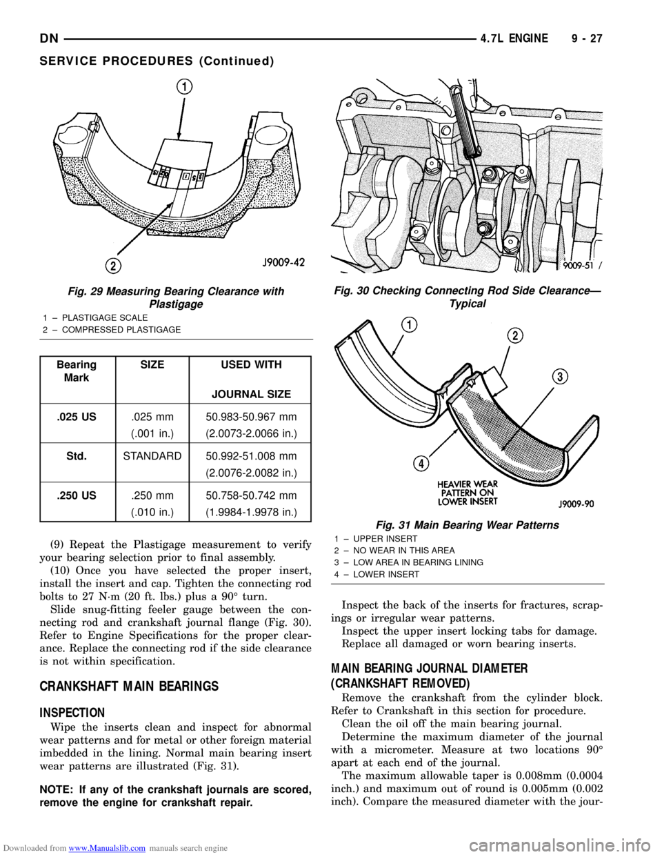
Slide snug-fitting feeler gauge between the con-
necting rod and crankshaft journal flange (Fig. 30).
Refer to Engine Specifications for the proper clear-
ance. Replace the connecting rod if the side clearance
is not within specification.
CRANKSHAFT MAIN BEARINGS
INSPECTION
Wipe the inserts clean and inspect for abnormal
wear patterns and for metal or other foreign material
imbedded in the lining. Normal main bearing insert
wear patterns are illustrated (Fig. 31).
NOTE: If any of the crankshaft journals are scored,
remove the engine for crankshaft repair.Inspect the back of the inserts for fractures, scrap-
ings or irregular wear patterns.
Inspect the upper insert locking tabs for damage.
Replace all damaged or worn bearing inserts.
MAIN BEARING JOURNAL DIAMETER
(CRANKSHAFT REMOVED)
Remove the crankshaft from the cylinder block.
Refer to Crankshaft in this section for procedure.
Clean the oil off the main bearing journal.
Determine the maximum diameter of the journal
with a micrometer. Measure at two locations 90É
apart at each end of the journal.
The maximum allowable taper is 0.008mm (0.0004
inch.) and maximum out of round is 0.005mm (0.002
inch). Compare the measured diameter with the jour-
Fig. 29 Measuring Bearing Clearance with
Plastigage
1 ± PLASTIGAGE SCALE
2 ± COMPRESSED PLASTIGAGE
Bearing
MarkSIZE USED WITH
JOURNAL SIZE
.025 US.025 mm 50.983-50.967 mm
(.001 in.) (2.0073-2.0066 in.)
Std.STANDARD 50.992-51.008 mm
(2.0076-2.0082 in.)
.250 US.250 mm 50.758-50.742 mm
(.010 in.) (1.9984-1.9978 in.)
Fig. 30 Checking Connecting Rod Side ClearanceÐ
Typical
Fig. 31 Main Bearing Wear Patterns
1 ± UPPER INSERT
2 ± NO WEAR IN THIS AREA
3 ± LOW AREA IN BEARING LINING
4 ± LOWER INSERT
DN4.7L ENGINE 9 - 27
SERVICE PROCEDURES (Continued)
Page 28 of 193
Downloaded from www.Manualslib.com manuals search engine nal diameter specification (Main Bearing Fitting
Chart). Select inserts required to obtain the specified
bearing-to-journal clearance.
Install the crankshaft into the cylinder block. Refer
to Crankshaft in this section for procedure.
CRANKSHAFT MAIN BEARING SELECTION
(1) Service main bearings are available in three
grades. The chart below identifies the three service
grades available.
REMOVAL AND INSTALLATION
ENGINE MOUNTSÐLEFT AND RIGHT
REMOVAL
(1) Disconnect the negative cable from the battery.
CAUTION: Remove the fan blade, fan clutch and
fan shroud before raising engine. Failure to do so
may cause damage to the fan blade, fan clutch and
fan shroud.
(2) Remove the fan blade, fan clutch and fan
shroud. Refer to Group 7. for procedure.
(3) Remove the engine oil filter.
(4) Support the engine with a suitable jack and a
block of wood across the full width of the engine oil
pan.
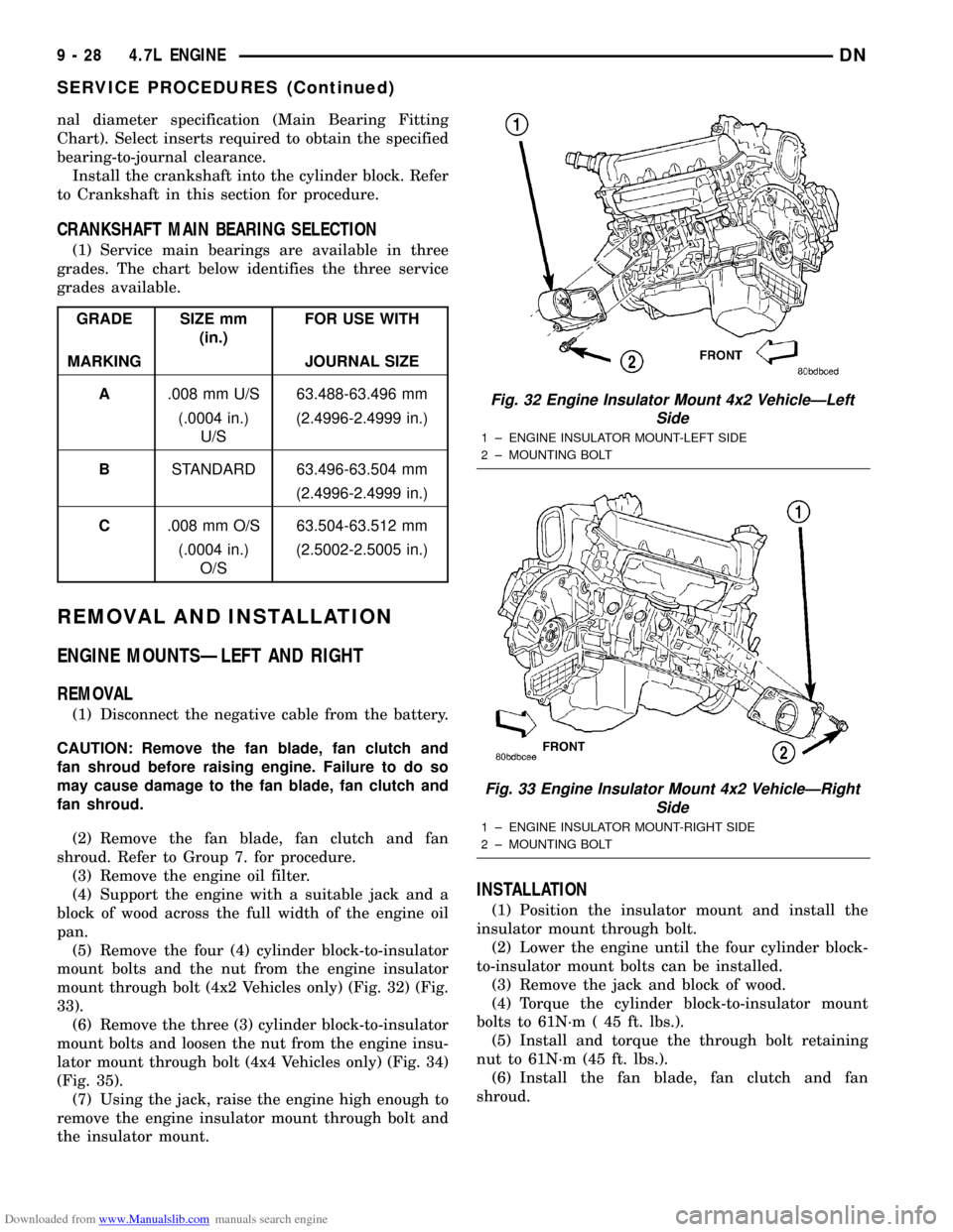
(5) Remove the four (4) cylinder block-to-insulator
mount bolts and the nut from the engine insulator
mount through bolt (4x2 Vehicles only) (Fig. 32) (Fig.
33).
(6) Remove the three (3) cylinder block-to-insulator
mount bolts and loosen the nut from the engine insu-
lator mount through bolt (4x4 Vehicles only) (Fig. 34)
(Fig. 35).
(7) Using the jack, raise the engine high enough to
remove the engine insulator mount through bolt and
the insulator mount.
INSTALLATION
(1) Position the insulator mount and install the
insulator mount through bolt.
(2) Lower the engine until the four cylinder block-
to-insulator mount bolts can be installed.
(3) Remove the jack and block of wood.
(4) Torque the cylinder block-to-insulator mount
bolts to 61N´m ( 45 ft. lbs.).
(5) Install and torque the through bolt retaining
nut to 61N´m (45 ft. lbs.).
(6) Install the fan blade, fan clutch and fan
shroud.
GRADE SIZE mm
(in.)FOR USE WITH
MARKING JOURNAL SIZE
A.008 mm U/S 63.488-63.496 mm
(.0004 in.)
U/S(2.4996-2.4999 in.)
BSTANDARD 63.496-63.504 mm
(2.4996-2.4999 in.)
C.008 mm O/S 63.504-63.512 mm
(.0004 in.)
O/S(2.5002-2.5005 in.)
Fig. 32 Engine Insulator Mount 4x2 VehicleÐLeft
Side
1 ± ENGINE INSULATOR MOUNT-LEFT SIDE
2 ± MOUNTING BOLT
Fig. 33 Engine Insulator Mount 4x2 VehicleÐRight
Side
1 ± ENGINE INSULATOR MOUNT-RIGHT SIDE
2 ± MOUNTING BOLT
9 - 28 4.7L ENGINEDN
SERVICE PROCEDURES (Continued)
Page 61 of 193
Downloaded from www.Manualslib.com manuals search engine INSTALLATION
(1) Lubricate camshaft journals with clean engine
oil.
NOTE: Position the right side camshaft so that the
camshaft sprocket dowel is near the 10 o'clock
position, This will place the camshaft at the neutral
position easing the installation of the camshaft
bearing caps.
(2) Position the camshaft into the cylinder head.
(3) Install the camshaft bearing caps, hand tighten
the retaining bolts.
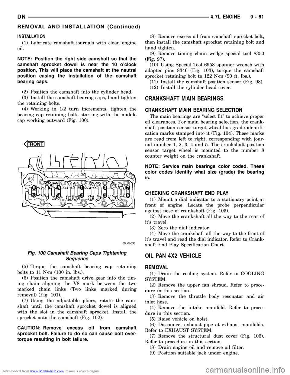
(4) Working in 1/2 turn increments, tighten the
bearing cap retaining bolts starting with the middle
cap working outward (Fig. 100).
(5) Torque the camshaft bearing cap retaining
bolts to 11 N´m (100 in. lbs.).
(6) Position the camshaft drive gear into the tim-
ing chain aligning the V8 mark between the two
marked chain links (Two links marked during
removal) (Fig. 101).
(7) Using the adjustable pliers, rotate the cam-
shaft until the camshaft sprocket dowel is aligned
with the slot in the camshaft sprocket. Install the
sprocket onto the camshaft (Fig. 102).
CAUTION: Remove excess oil from camshaft
sprocket bolt. Failure to do so can cause bolt over-
torque resulting in bolt failure.(8) Remove excess oil from camshaft sprocket bolt,
then install the camshaft sprocket retaining bolt and
hand tighten.
(9) Remove timing chain wedge special tool 8350
(Fig. 97).
(10) Using Special Tool 6958 spanner wrench with
adapter pins 8346 (Fig. 103), torque the camshaft
sprocket retaining bolt to 122 N´m (90 ft. lbs.).
(11) Install the camshaft position sensor (Fig. 98).
(12) Install the cylinder head cover.
CRANKSHAFT MAIN BEARINGS
CRANKSHAFT MAIN BEARING SELECTION
The main bearings are ªselect fitº to achieve proper
oil clearances. For main bearing selection, the crank-
shaft position sensor target wheel has grade identifi-
cation marks stamped into it (Fig. 104). These marks
are read from left to right, corresponding with jour-
nal number 1, 2, 3, 4 and 5. The crankshaft position
sensor target wheel is mounted to the number 8
counter weight on the crankshaft.
NOTE: Service main bearings color coded. These
color codes identify what size (grade) the bearing
is.
CHECKING CRANKSHAFT END PLAY
(1) Mount a dial indicator to a stationary point at
front of engine. Locate the probe perpendicular
against nose of crankshaft (Fig. 105).
(2) Move the crankshaft all the way to the rear of
it's travel.
(3) Zero the dial indicator.
(4) Move the crankshaft all the way to the front of
it's travel and read the dial indicator. Refer to Crank-
shaft End Play Specification Chart.
OIL PAN 4X2 VEHICLE
REMOVAL
(1) Drain the cooling system. Refer to COOLING
SYSTEM.
(2) Remove the upper fan shroud. Refer to proce-
dure in this section.
(3) Remove the throttle body resonator and air
inlet hose.
(4) Remove the intake manifold. Refer to proce-
dure in this section.
(5) Raise vehicle on hoist.
(6) Disconnect exhaust pipe at exhaust manifolds.
Refer to EXHAUST SYSTEM.
(7) Remove the structural dust cover (Fig. 106).
Refer to procedure in this section.
(8) Drain engine oil and remove oil filter.
(9) Position suitable jack under engine.
Fig. 100 Camshaft Bearing Caps Tightening
Sequence
DN4.7L ENGINE 9 - 61
REMOVAL AND INSTALLATION (Continued)
Page 68 of 193
Downloaded from www.Manualslib.com manuals search engine If connecting rod bearing bores show damage, the
cylinder heads must be removed to service the piston
and rod assemblies. If the bedplate or the cylinder
block main bearing bores show damage the engine
must be replaced.
(1) If required, remove the main bearing halves
from the cylinder block and bedplate.
(2) Thoroughly clean the bedplate to cylinder block
sealing surfaces and main bearing bores. Remove all
oil and sealant residue.
(3) Inspect the bedplate main bearing bores for
cracks, scoring or severe blueing. If either condition
exists the engine must be replaced.
(4) Inspect the crankshaft thrust washer for scor-
ing, scratches or blueing. If either condition exist
replace the thrust washer.
(5) Inspect the oil pan gasket/windage tray for
splits, tears or cracks in the gasket sealing surfaces.
Replace gasket as necessary.
INSTALLATION
CAUTION: Main bearings are select fit. Refer to
Crankshaft Main Bearings in this section for proper
bearing selections.(1) Lubricate upper main bearing halves with
clean engine oil.
CAUTION: When installing crankshaft, use care not
to damage bearing surfaces on the crankshaft.
NOTE: Apply sealant to the tone wheel retaining
screws prior to installation.
(2) Install the crankshaft tone wheel. torque the
mounting screws to 22 N´m (21 ft. lbs.).
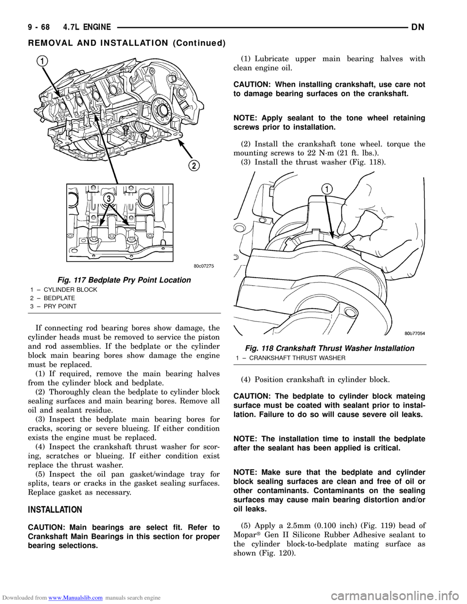
(3) Install the thrust washer (Fig. 118).
(4) Position crankshaft in cylinder block.
CAUTION: The bedplate to cylinder block mateing
surface must be coated with sealant prior to instal-
lation. Failure to do so will cause severe oil leaks.
NOTE: The installation time to install the bedplate
after the sealant has been applied is critical.
NOTE: Make sure that the bedplate and cylinder
block sealing surfaces are clean and free of oil or
other contaminants. Contaminants on the sealing
surfaces may cause main bearing distortion and/or
oil leaks.
(5) Apply a 2.5mm (0.100 inch) (Fig. 119) bead of
MopartGen II Silicone Rubber Adhesive sealant to
the cylinder block-to-bedplate mating surface as
shown (Fig. 120).
Fig. 117 Bedplate Pry Point Location
1 ± CYLINDER BLOCK
2 ± BEDPLATE
3 ± PRY POINT
Fig. 118 Crankshaft Thrust Washer Installation
1 ± CRANKSHAFT THRUST WASHER
9 - 68 4.7L ENGINEDN
REMOVAL AND INSTALLATION (Continued)
Page 74 of 193
Downloaded from www.Manualslib.com manuals search engine ENGINE CORE PLUGS
REMOVAL
(1) Drain the cooling system. Refer to Group 7,
Cooling System for procedure.
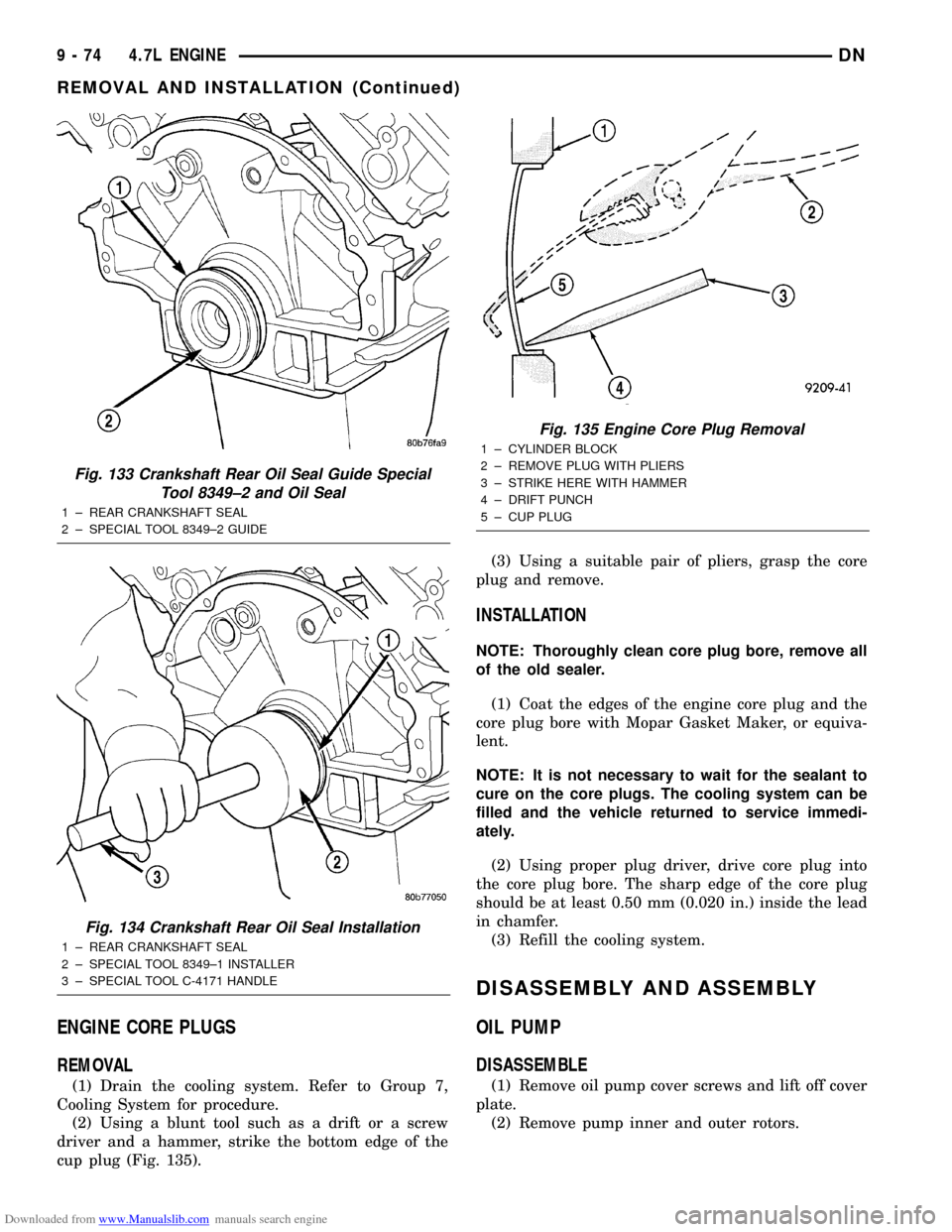
(2) Using a blunt tool such as a drift or a screw
driver and a hammer, strike the bottom edge of the
cup plug (Fig. 135).(3) Using a suitable pair of pliers, grasp the core
plug and remove.
INSTALLATION
NOTE: Thoroughly clean core plug bore, remove all
of the old sealer.
(1) Coat the edges of the engine core plug and the
core plug bore with Mopar Gasket Maker, or equiva-
lent.
NOTE: It is not necessary to wait for the sealant to
cure on the core plugs. The cooling system can be
filled and the vehicle returned to service immedi-
ately.
(2) Using proper plug driver, drive core plug into
the core plug bore. The sharp edge of the core plug
should be at least 0.50 mm (0.020 in.) inside the lead
in chamfer.
(3) Refill the cooling system.
DISASSEMBLY AND ASSEMBLY
OIL PUMP
DISASSEMBLE
(1) Remove oil pump cover screws and lift off cover
plate.
(2) Remove pump inner and outer rotors.
Fig. 133 Crankshaft Rear Oil Seal Guide Special
Tool 8349±2 and Oil Seal
1 ± REAR CRANKSHAFT SEAL
2 ± SPECIAL TOOL 8349±2 GUIDE
Fig. 134 Crankshaft Rear Oil Seal Installation
1 ± REAR CRANKSHAFT SEAL
2 ± SPECIAL TOOL 8349±1 INSTALLER
3 ± SPECIAL TOOL C-4171 HANDLE
Fig. 135 Engine Core Plug Removal
1 ± CYLINDER BLOCK
2 ± REMOVE PLUG WITH PLIERS
3 ± STRIKE HERE WITH HAMMER
4 ± DRIFT PUNCH
5 ± CUP PLUG
9 - 74 4.7L ENGINEDN
REMOVAL AND INSTALLATION (Continued)
Page 75 of 193
Downloaded from www.Manualslib.com manuals search engine NOTE: Once the oil pressure relief valve, cup plug,
and pin are removed, the pump assembly must be
replaced.
(3) If it is necessary to remove the pressure relief
valve, drive the roll pin from pump housing and
remove cup plug, spring and valve.
ASSEMBLE
(1) Wash all parts in a suitable solvent and inspect
carefully for damage or wear.
(2) Install inner and outer rotors
(3) Install oil pump cover plate and install cover
bolts and tighten them to 12 N´m (105 in. lbs.).
(4) Prime oil pump before installation by filling
rotor cavity with engine oil.
(5) If oil pressure is low and pump is within spec-
ifications, inspect for worn engine bearings or other
causes for oil pressure loss.
CLEANING AND INSPECTION
INTAKE MANIFOLD
CLEANING
NOTE: There is NO approved repair procedure for
the intake manifold. If severe damage is found dur-
ing inspection, the intake manifold must be
replaced.
Before installing the intake manifold thoroughly
clean the mating surfaces. Use a suitable cleaning
solvent, then air dry.
INSPECTION
(1) Inspect the intake sealing surface for cracks,
nicks and distortion.
(2) Inspect the intake manifold vacuum hose fit-
tings for looseness or blockage.
(3) Inspect the manifold to throttle body mating
surface for cracks, nicks and distortion.
EXHAUST MANIFOLD
CLEANING
(1) Clean the exhaust manifold using a suitable
cleaning solvent, then allow to air dry.
(2) Clean all gasket residue from the manifold
mating surface.
INSPECTION
(1) Inspect the exhaust manifold for cracks in the
mating surface and at every mounting bolt hole.
(2) Using a straight edge and a feeler gauge, check
the mating surface for warp and twist.(3) Inspect the manifold to exhaust pipe mating
surface for cracks, gouges, or other damage that
would prevent sealing.
CYLINDER HEADS
CLEANING
CYLINDER HEAD GASKET SURFACE PREPARATION
To ensure engine gasket sealing, proper surface
preparation must be performed, especially with the
use of aluminum engine components.
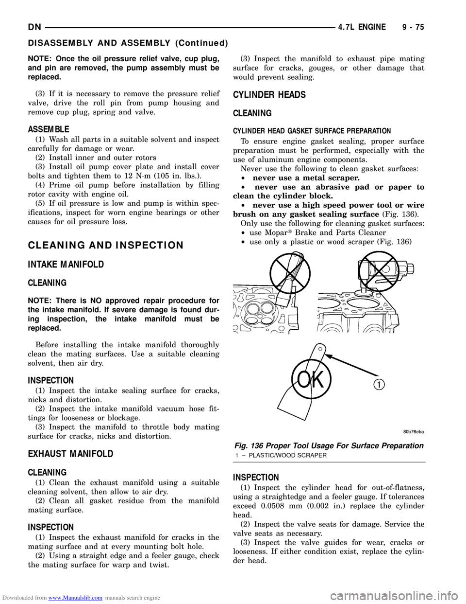
Never use the following to clean gasket surfaces:
²never use a metal scraper.
²never use an abrasive pad or paper to
clean the cylinder block.
²never use a high speed power tool or wire
brush on any gasket sealing surface(Fig. 136).
Only use the following for cleaning gasket surfaces:
²use MopartBrake and Parts Cleaner
²use only a plastic or wood scraper (Fig. 136)
INSPECTION
(1) Inspect the cylinder head for out-of-flatness,
using a straightedge and a feeler gauge. If tolerances
exceed 0.0508 mm (0.002 in.) replace the cylinder
head.
(2) Inspect the valve seats for damage. Service the
valve seats as necessary.
(3) Inspect the valve guides for wear, cracks or
looseness. If either condition exist, replace the cylin-
der head.
Fig. 136 Proper Tool Usage For Surface Preparation
1 ± PLASTIC/WOOD SCRAPER
DN4.7L ENGINE 9 - 75
DISASSEMBLY AND ASSEMBLY (Continued)
Page 80 of 193
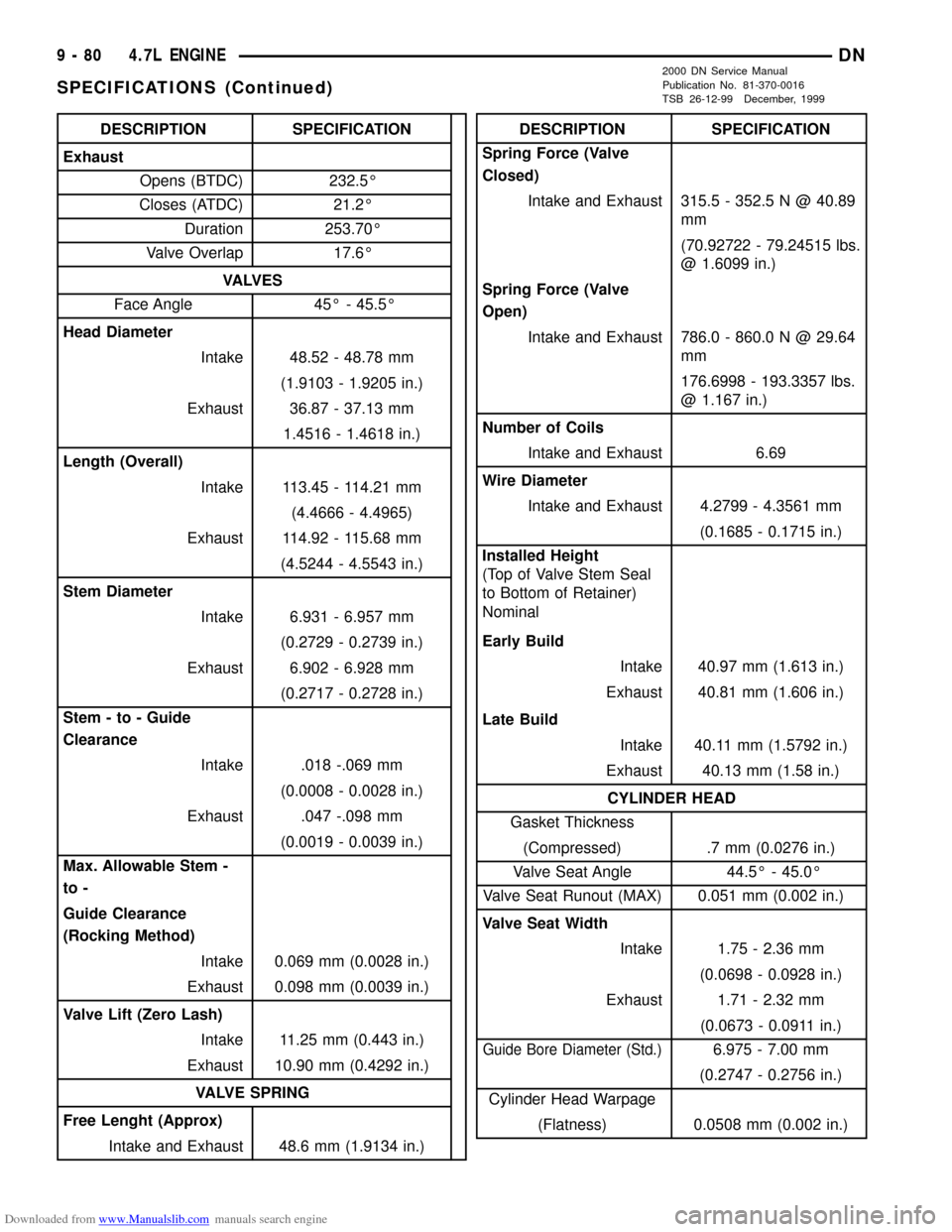
Downloaded from www.Manualslib.com manuals search engine DESCRIPTION SPECIFICATION
Exhaust
Opens (BTDC) 232.5É
Closes (ATDC) 21.2É
Duration 253.70É
Valve Overlap 17.6É
VA LV E S
Face Angle 45É - 45.5É
Head Diameter
Intake 48.52 - 48.78 mm
(1.9103 - 1.9205 in.)
Exhaust 36.87 - 37.13 mm
1.4516 - 1.4618 in.)
Length (Overall)
Intake 113.45 - 114.21 mm
(4.4666 - 4.4965)
Exhaust 114.92 - 115.68 mm
(4.5244 - 4.5543 in.)
Stem Diameter
Intake 6.931 - 6.957 mm
(0.2729 - 0.2739 in.)
Exhaust 6.902 - 6.928 mm
(0.2717 - 0.2728 in.)
Stem - to - Guide
Clearance
Intake .018 -.069 mm
(0.0008 - 0.0028 in.)
Exhaust .047 -.098 mm
(0.0019 - 0.0039 in.)
Max. Allowable Stem -
to -
Guide Clearance
(Rocking Method)
Intake 0.069 mm (0.0028 in.)
Exhaust 0.098 mm (0.0039 in.)
Valve Lift (Zero Lash)
Intake 11.25 mm (0.443 in.)
Exhaust 10.90 mm (0.4292 in.)
VALVE SPRING
Free Lenght (Approx)
Intake and Exhaust 48.6 mm (1.9134 in.)DESCRIPTION SPECIFICATION
Spring Force (Valve
Closed)
Intake and Exhaust 315.5 - 352.5 N @ 40.89
mm
(70.92722 - 79.24515 lbs.
@ 1.6099 in.)
Spring Force (Valve
Open)
Intake and Exhaust 786.0 - 860.0 N @ 29.64
mm
176.6998 - 193.3357 lbs.
@ 1.167 in.)
Number of Coils
Intake and Exhaust 6.69
Wire Diameter
Intake and Exhaust 4.2799 - 4.3561 mm
(0.1685 - 0.1715 in.)
Installed Height
(Top of Valve Stem Seal
to Bottom of Retainer)
Nominal
Early Build
Intake 40.97 mm (1.613 in.)
Exhaust 40.81 mm (1.606 in.)
Late Build
Intake 40.11 mm (1.5792 in.)
Exhaust 40.13 mm (1.58 in.)
CYLINDER HEAD
Gasket Thickness
(Compressed) .7 mm (0.0276 in.)
Valve Seat Angle 44.5É - 45.0É
Valve Seat Runout (MAX) 0.051 mm (0.002 in.)
Valve Seat Width
Intake 1.75 - 2.36 mm
(0.0698 - 0.0928 in.)
Exhaust 1.71 - 2.32 mm
(0.0673 - 0.0911 in.)
Guide Bore Diameter (Std.)6.975 - 7.00 mm
(0.2747 - 0.2756 in.)
Cylinder Head Warpage
(Flatness) 0.0508 mm (0.002 in.)
9 - 80 4.7L ENGINEDN
SPECIFICATIONS (Continued)
2000 DN Service Manual
Publication No. 81-370-0016
TSB 26-12-99 December, 1999
Page 86 of 193
Downloaded from www.Manualslib.com manuals search engine 5.2L ENGINE
TABLE OF CONTENTS
page page
DESCRIPTION AND OPERATION
ENGINE................................86
ENGINE LUBRICATION SYSTEM.............87
EXHAUST MANIFOLD.....................89
INTAKE MANIFOLD.......................89
CYLINDER HEAD COVER GASKET...........90
CYLINDER HEAD.........................90
VALVES AND VALVE SPRINGS..............90
ENGINE OIL PAN.........................90
CRANKSHAFT OIL SEALS..................90
PISTON AND CONNECTING ROD............90
CRANKSHAFT MAIN BEARINGS.............91
CRANKSHAFT...........................91
SERVICE PROCEDURES
FORM-IN-PLACE GASKETS.................91
ENGINE PERFORMANCE..................92
ENGINE OIL.............................92
REPAIR DAMAGED OR WORN THREADS......94
CYLINDER BOREÐHONING................94
HYDROSTATIC LOCK.....................95
VALVE TIMING...........................95
VALVE SERVICE.........................95
MEASURING TIMING CHAIN STRETCH........97
PISTONSÐFITTING.......................98
PISTON RINGSÐFITTING..................98
CONNECTING ROD BEARINGSÐFITTING.....100
CRANKSHAFT MAIN BEARINGSÐFITTING....100
REMOVAL AND INSTALLATION
ENGINE MOUNTSÐFRONT................100
ENGINE MOUNTÐREAR..................102
ENGINE ASSEMBLY......................102
INTAKE MANIFOLD......................103
EXHAUST MANIFOLD....................105
CYLINDER HEAD COVER.................106
ROCKER ARMS AND PUSH RODS..........107
VALVE SPRING AND STEM SEAL
REPLACEMENT-IN VEHICLE.............107CYLINDER HEAD........................107
VALVES AND VALVE SPRINGS.............108
HYDRAULIC TAPPETS....................109
VIBRATION DAMPER.....................109
TIMING CHAIN COVER...................110
TIMING CHAIN..........................111
CAMSHAFT............................111
CAMSHAFT BEARINGS...................113
CRANKSHAFT MAIN BEARINGS............113
DISTRIBUTOR DRIVE SHAFT BUSHING......114
OILPAN...............................115
PISTON AND CONNECTING ROD ASSEMBLY . . 116
CRANKSHAFT..........................116
OIL PUMP.............................117
CRANKSHAFT OIL SEALÐFRONT...........117
CRANKSHAFT OIL SEALSÐREAR...........118
ENGINE CORE OIL AND CAMSHAFT PLUGS . . 120
DISASSEMBLY AND ASSEMBLY
VALVE SERVICE........................121
OIL PUMP.............................123
CYLINDER BLOCK.......................124
CLEANING AND INSPECTION
CYLINDER HEAD COVER.................124
CYLINDER HEAD ASSEMBLY..............124
PISTON AND CONNECTING ROD ASSEMBLY . . 124
OILPAN...............................124
OIL PUMP.............................125
CYLINDER BLOCK.......................127
INTAKE MANIFOLD......................127
EXHAUST MANIFOLD....................127
SPECIFICATIONS
5.2L ENGINE SPECIFICATIONS.............128
TORQUE SPECIFICATIONS................132
SPECIAL TOOLS
5.2L ENGINE...........................132
DESCRIPTION AND OPERATION
ENGINE
DESCRIPTION
The 5.2 Liter (318 CID) eight-cylinder engine is a
V-Type lightweight, single cam, overhead valve
engine with hydraulic roller tappets.
The engine lubrication system consists of a rotor
type oil pump and a full flow oil filter.The cylinders are numbered from front to rear; 1,
3, 5, 7 on the left bank and 2, 4, 6, 8 on the right
bank. The firing order is 1-8-4-3-6-5-7-2 (Fig. 1). This
engine is designed for unleaded fuel.
The engine serial number is stamped into a
machined pad located on the left, front corner of the
cylinder block. When component part replacement is
necessary, use the engine type and serial number for
reference (Fig. 2).
9 - 86 5.2L ENGINEDN
Page 91 of 193
Downloaded from www.Manualslib.com manuals search engine CRANKSHAFT MAIN BEARINGS
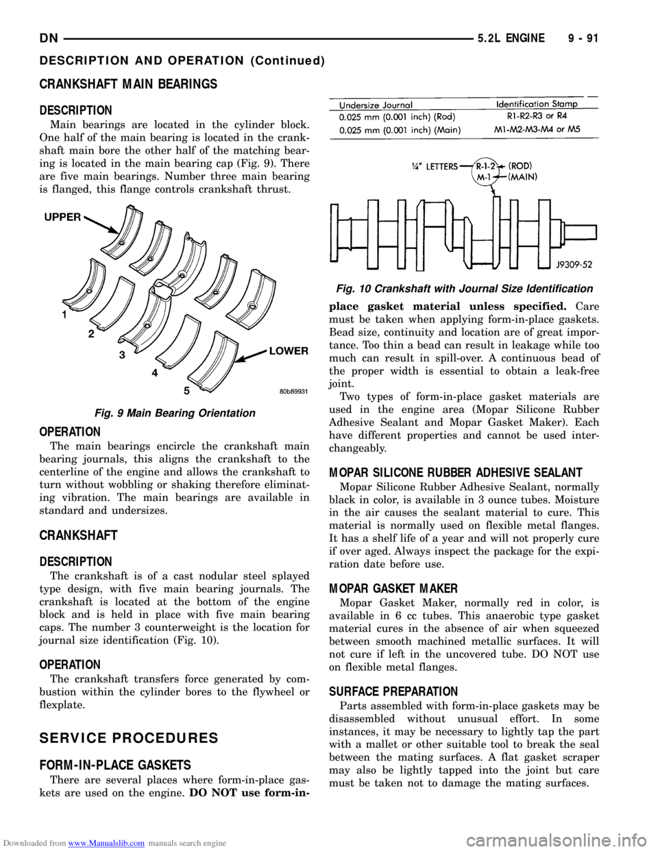
DESCRIPTION
Main bearings are located in the cylinder block.
One half of the main bearing is located in the crank-
shaft main bore the other half of the matching bear-
ing is located in the main bearing cap (Fig. 9). There
are five main bearings. Number three main bearing
is flanged, this flange controls crankshaft thrust.
OPERATION
The main bearings encircle the crankshaft main
bearing journals, this aligns the crankshaft to the
centerline of the engine and allows the crankshaft to
turn without wobbling or shaking therefore eliminat-
ing vibration. The main bearings are available in
standard and undersizes.
CRANKSHAFT
DESCRIPTION
The crankshaft is of a cast nodular steel splayed
type design, with five main bearing journals. The
crankshaft is located at the bottom of the engine
block and is held in place with five main bearing
caps. The number 3 counterweight is the location for
journal size identification (Fig. 10).
OPERATION
The crankshaft transfers force generated by com-
bustion within the cylinder bores to the flywheel or
flexplate.
SERVICE PROCEDURES
FORM-IN-PLACE GASKETS
There are several places where form-in-place gas-
kets are used on the engine.DO NOT use form-in-place gasket material unless specified.Care
must be taken when applying form-in-place gaskets.
Bead size, continuity and location are of great impor-
tance. Too thin a bead can result in leakage while too
much can result in spill-over. A continuous bead of
the proper width is essential to obtain a leak-free
joint.
Two types of form-in-place gasket materials are
used in the engine area (Mopar Silicone Rubber
Adhesive Sealant and Mopar Gasket Maker). Each
have different properties and cannot be used inter-
changeably.
MOPAR SILICONE RUBBER ADHESIVE SEALANT
Mopar Silicone Rubber Adhesive Sealant, normally
black in color, is available in 3 ounce tubes. Moisture
in the air causes the sealant material to cure. This
material is normally used on flexible metal flanges.
It has a shelf life of a year and will not properly cure
if over aged. Always inspect the package for the expi-
ration date before use.
MOPAR GASKET MAKER
Mopar Gasket Maker, normally red in color, is
available in 6 cc tubes. This anaerobic type gasket
material cures in the absence of air when squeezed
between smooth machined metallic surfaces. It will
not cure if left in the uncovered tube. DO NOT use
on flexible metal flanges.
SURFACE PREPARATION
Parts assembled with form-in-place gaskets may be
disassembled without unusual effort. In some
instances, it may be necessary to lightly tap the part
with a mallet or other suitable tool to break the seal
between the mating surfaces. A flat gasket scraper
may also be lightly tapped into the joint but care
must be taken not to damage the mating surfaces.
Fig. 9 Main Bearing Orientation
Fig. 10 Crankshaft with Journal Size Identification
DN5.2L ENGINE 9 - 91
DESCRIPTION AND OPERATION (Continued)