Overhead DODGE DURANGO 1998 1.G Workshop Manual
[x] Cancel search | Manufacturer: DODGE, Model Year: 1998, Model line: DURANGO, Model: DODGE DURANGO 1998 1.GPages: 193, PDF Size: 5.65 MB
Page 2 of 193

Downloaded from www.Manualslib.com manuals search engine OIL PUMP..............................69
ENGINE OIL PRESSURE SENDING UNIT......70
CRANKSHAFT OIL SEALÐFRONT............70
CRANKSHAFT OIL SEALÐREAR.............73
ENGINE CORE PLUGS....................74
DISASSEMBLY AND ASSEMBLY
OIL PUMP..............................74
CLEANING AND INSPECTION
INTAKE MANIFOLD.......................75
EXHAUST MANIFOLD.....................75CYLINDER HEADS........................75
PISTON AND CONNECTING ROD............76
OILPAN................................76
OIL PUMP..............................76
CYLINDER BLOCK........................76
SPECIFICATIONS
4.7L ENGINE............................78
TORQUE...............................81
SPECIAL TOOLS
4.7L ENGINE............................82
DESCRIPTION AND OPERATION
ENGINE
DESCRIPTION
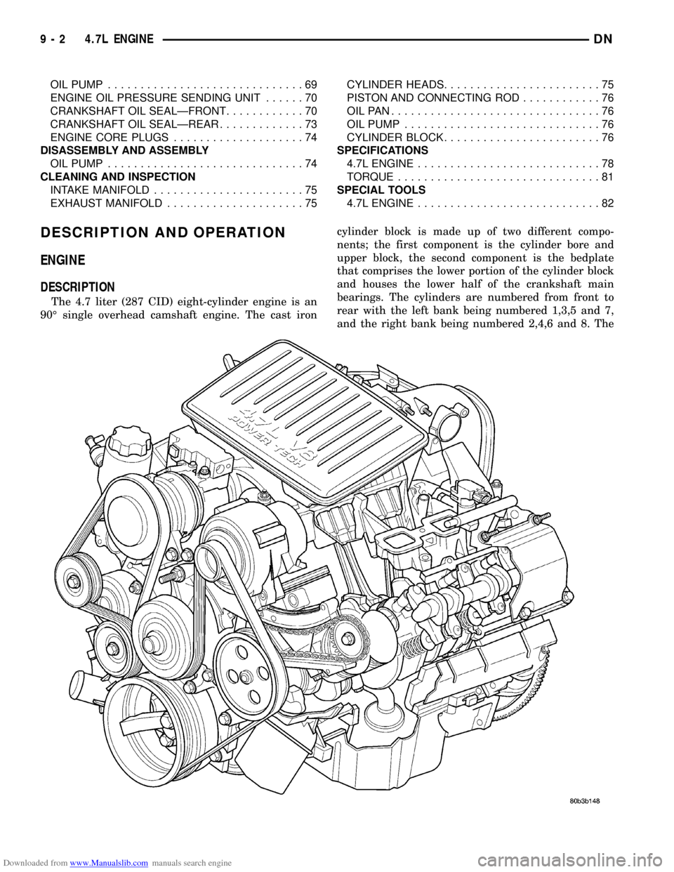
The 4.7 liter (287 CID) eight-cylinder engine is an
90É single overhead camshaft engine. The cast ironcylinder block is made up of two different compo-
nents; the first component is the cylinder bore and
upper block, the second component is the bedplate
that comprises the lower portion of the cylinder block
and houses the lower half of the crankshaft main
bearings. The cylinders are numbered from front to
rear with the left bank being numbered 1,3,5 and 7,
and the right bank being numbered 2,4,6 and 8. The
9 - 2 4.7L ENGINEDN
Page 86 of 193

Downloaded from www.Manualslib.com manuals search engine 5.2L ENGINE
TABLE OF CONTENTS
page page
DESCRIPTION AND OPERATION
ENGINE................................86
ENGINE LUBRICATION SYSTEM.............87
EXHAUST MANIFOLD.....................89
INTAKE MANIFOLD.......................89
CYLINDER HEAD COVER GASKET...........90
CYLINDER HEAD.........................90
VALVES AND VALVE SPRINGS..............90
ENGINE OIL PAN.........................90
CRANKSHAFT OIL SEALS..................90
PISTON AND CONNECTING ROD............90
CRANKSHAFT MAIN BEARINGS.............91
CRANKSHAFT...........................91
SERVICE PROCEDURES
FORM-IN-PLACE GASKETS.................91
ENGINE PERFORMANCE..................92
ENGINE OIL.............................92
REPAIR DAMAGED OR WORN THREADS......94
CYLINDER BOREÐHONING................94
HYDROSTATIC LOCK.....................95
VALVE TIMING...........................95
VALVE SERVICE.........................95
MEASURING TIMING CHAIN STRETCH........97
PISTONSÐFITTING.......................98
PISTON RINGSÐFITTING..................98
CONNECTING ROD BEARINGSÐFITTING.....100
CRANKSHAFT MAIN BEARINGSÐFITTING....100
REMOVAL AND INSTALLATION
ENGINE MOUNTSÐFRONT................100
ENGINE MOUNTÐREAR..................102
ENGINE ASSEMBLY......................102
INTAKE MANIFOLD......................103
EXHAUST MANIFOLD....................105
CYLINDER HEAD COVER.................106
ROCKER ARMS AND PUSH RODS..........107
VALVE SPRING AND STEM SEAL
REPLACEMENT-IN VEHICLE.............107CYLINDER HEAD........................107
VALVES AND VALVE SPRINGS.............108
HYDRAULIC TAPPETS....................109
VIBRATION DAMPER.....................109
TIMING CHAIN COVER...................110
TIMING CHAIN..........................111
CAMSHAFT............................111
CAMSHAFT BEARINGS...................113
CRANKSHAFT MAIN BEARINGS............113
DISTRIBUTOR DRIVE SHAFT BUSHING......114
OILPAN...............................115
PISTON AND CONNECTING ROD ASSEMBLY . . 116
CRANKSHAFT..........................116
OIL PUMP.............................117
CRANKSHAFT OIL SEALÐFRONT...........117
CRANKSHAFT OIL SEALSÐREAR...........118
ENGINE CORE OIL AND CAMSHAFT PLUGS . . 120
DISASSEMBLY AND ASSEMBLY
VALVE SERVICE........................121
OIL PUMP.............................123
CYLINDER BLOCK.......................124
CLEANING AND INSPECTION
CYLINDER HEAD COVER.................124
CYLINDER HEAD ASSEMBLY..............124
PISTON AND CONNECTING ROD ASSEMBLY . . 124
OILPAN...............................124
OIL PUMP.............................125
CYLINDER BLOCK.......................127
INTAKE MANIFOLD......................127
EXHAUST MANIFOLD....................127
SPECIFICATIONS
5.2L ENGINE SPECIFICATIONS.............128
TORQUE SPECIFICATIONS................132
SPECIAL TOOLS
5.2L ENGINE...........................132
DESCRIPTION AND OPERATION
ENGINE
DESCRIPTION
The 5.2 Liter (318 CID) eight-cylinder engine is a
V-Type lightweight, single cam, overhead valve
engine with hydraulic roller tappets.
The engine lubrication system consists of a rotor
type oil pump and a full flow oil filter.The cylinders are numbered from front to rear; 1,
3, 5, 7 on the left bank and 2, 4, 6, 8 on the right
bank. The firing order is 1-8-4-3-6-5-7-2 (Fig. 1). This
engine is designed for unleaded fuel.
The engine serial number is stamped into a
machined pad located on the left, front corner of the
cylinder block. When component part replacement is
necessary, use the engine type and serial number for
reference (Fig. 2).
9 - 86 5.2L ENGINEDN
Page 137 of 193

Downloaded from www.Manualslib.com manuals search engine DESCRIPTION AND OPERATION
ENGINE
DESCRIPTION
The 5.9 Liter (360 CID) eight-cylinder engine is a
V-Type lightweight, single cam, overhead valve
engine with hydraulic roller tappets. This engine is
designed for unleaded fuel.
The engine lubrication system consists of a rotor
type oil pump and a full flow oil filter.
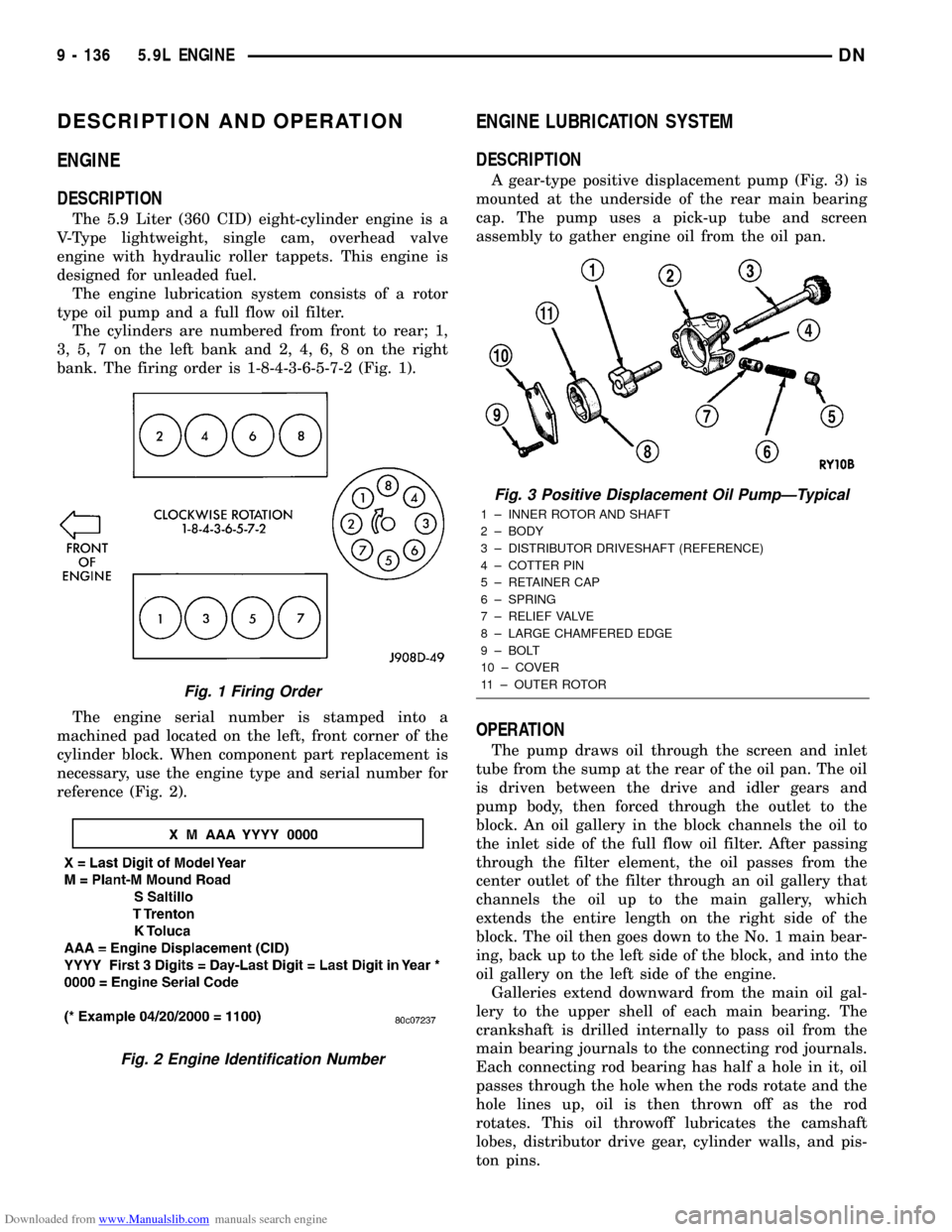
The cylinders are numbered from front to rear; 1,
3, 5, 7 on the left bank and 2, 4, 6, 8 on the right
bank. The firing order is 1-8-4-3-6-5-7-2 (Fig. 1).
The engine serial number is stamped into a
machined pad located on the left, front corner of the
cylinder block. When component part replacement is
necessary, use the engine type and serial number for
reference (Fig. 2).
ENGINE LUBRICATION SYSTEM
DESCRIPTION
A gear-type positive displacement pump (Fig. 3) is
mounted at the underside of the rear main bearing
cap. The pump uses a pick-up tube and screen
assembly to gather engine oil from the oil pan.
OPERATION
The pump draws oil through the screen and inlet
tube from the sump at the rear of the oil pan. The oil
is driven between the drive and idler gears and
pump body, then forced through the outlet to the
block. An oil gallery in the block channels the oil to
the inlet side of the full flow oil filter. After passing
through the filter element, the oil passes from the
center outlet of the filter through an oil gallery that
channels the oil up to the main gallery, which
extends the entire length on the right side of the
block. The oil then goes down to the No. 1 main bear-
ing, back up to the left side of the block, and into the
oil gallery on the left side of the engine.
Galleries extend downward from the main oil gal-
lery to the upper shell of each main bearing. The
crankshaft is drilled internally to pass oil from the
main bearing journals to the connecting rod journals.
Each connecting rod bearing has half a hole in it, oil
passes through the hole when the rods rotate and the
hole lines up, oil is then thrown off as the rod
rotates. This oil throwoff lubricates the camshaft
lobes, distributor drive gear, cylinder walls, and pis-
ton pins.
Fig. 1 Firing Order
Fig. 2 Engine Identification Number
Fig. 3 Positive Displacement Oil PumpÐTypical
1 ± INNER ROTOR AND SHAFT
2 ± BODY
3 ± DISTRIBUTOR DRIVESHAFT (REFERENCE)
4 ± COTTER PIN
5 ± RETAINER CAP
6 ± SPRING
7 ± RELIEF VALVE
8 ± LARGE CHAMFERED EDGE
9 ± BOLT
10 ± COVER
11 ± OUTER ROTOR
9 - 136 5.9L ENGINEDN