Vacuum DODGE DURANGO 1998 1.G Workshop Manual
[x] Cancel search | Manufacturer: DODGE, Model Year: 1998, Model line: DURANGO, Model: DODGE DURANGO 1998 1.GPages: 193, PDF Size: 5.65 MB
Page 8 of 193
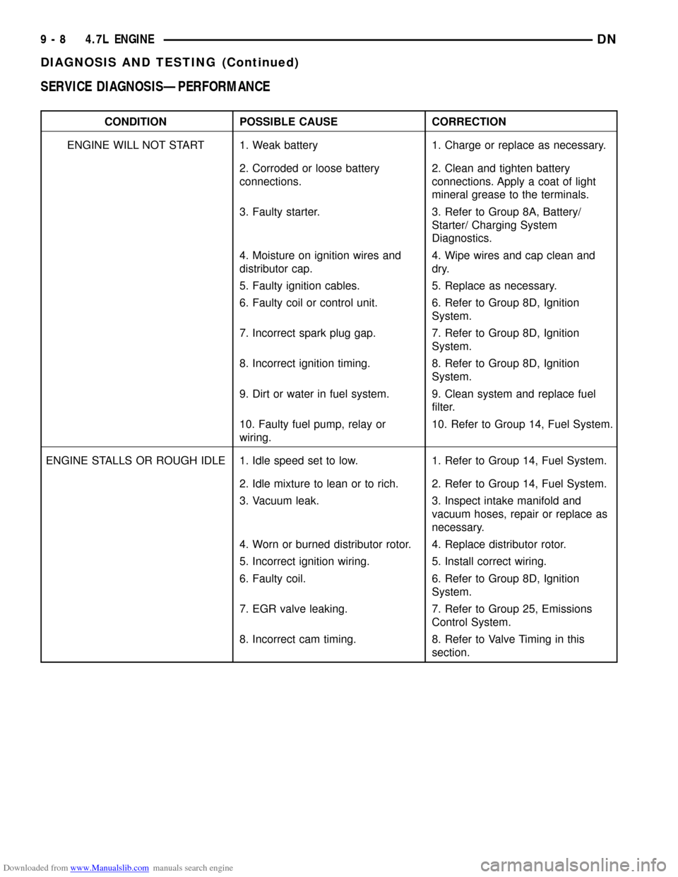
Downloaded from www.Manualslib.com manuals search engine SERVICE DIAGNOSISÐPERFORMANCE
CONDITION POSSIBLE CAUSE CORRECTION
ENGINE WILL NOT START 1. Weak battery 1. Charge or replace as necessary.
2. Corroded or loose battery
connections.2. Clean and tighten battery
connections. Apply a coat of light
mineral grease to the terminals.
3. Faulty starter. 3. Refer to Group 8A, Battery/
Starter/ Charging System
Diagnostics.
4. Moisture on ignition wires and
distributor cap.4. Wipe wires and cap clean and
dry.
5. Faulty ignition cables. 5. Replace as necessary.
6. Faulty coil or control unit. 6. Refer to Group 8D, Ignition
System.
7. Incorrect spark plug gap. 7. Refer to Group 8D, Ignition
System.
8. Incorrect ignition timing. 8. Refer to Group 8D, Ignition
System.
9. Dirt or water in fuel system. 9. Clean system and replace fuel
filter.
10. Faulty fuel pump, relay or
wiring.10. Refer to Group 14, Fuel System.
ENGINE STALLS OR ROUGH IDLE 1. Idle speed set to low. 1. Refer to Group 14, Fuel System.
2. Idle mixture to lean or to rich. 2. Refer to Group 14, Fuel System.
3. Vacuum leak. 3. Inspect intake manifold and
vacuum hoses, repair or replace as
necessary.
4. Worn or burned distributor rotor. 4. Replace distributor rotor.
5. Incorrect ignition wiring. 5. Install correct wiring.
6. Faulty coil. 6. Refer to Group 8D, Ignition
System.
7. EGR valve leaking. 7. Refer to Group 25, Emissions
Control System.
8. Incorrect cam timing. 8. Refer to Valve Timing in this
section.
9 - 8 4.7L ENGINEDN
DIAGNOSIS AND TESTING (Continued)
Page 11 of 193
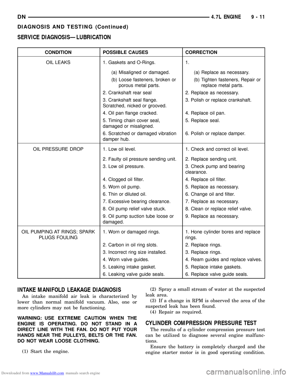
Downloaded from www.Manualslib.com manuals search engine SERVICE DIAGNOSISÐLUBRICATION
CONDITION POSSIBLE CAUSES CORRECTION
OIL LEAKS 1. Gaskets and O-Rings. 1.
(a) Misaligned or damaged. (a) Replace as necessary.
(b) Loose fasteners, broken or
porous metal parts.(b) Tighten fasteners, Repair or
replace metal parts.
2. Crankshaft rear seal 2. Replace as necessary.
3. Crankshaft seal flange.
Scratched, nicked or grooved.3. Polish or replace crankshaft.
4. Oil pan flange cracked. 4. Replace oil pan.
5. Timing chain cover seal,
damaged or misaligned.5. Replace seal.
6. Scratched or damaged vibration
damper hub.6. Polish or replace damper.
OIL PRESSURE DROP 1. Low oil level. 1. Check and correct oil level.
2. Faulty oil pressure sending unit. 2. Replace sending unit.
3. Low oil pressure. 3. Check pump and bearing
clearance.
4. Clogged oil filter. 4. Replace oil filter.
5. Worn oil pump. 5. Replace as necessary.
6. Thin or diluted oil. 6. Change oil and filter.
7. Excessive bearing clearance. 7. Replace as necessary.
8. Oil pump relief valve stuck. 8. Clean or replace relief valve.
9. Oil pump suction tube loose or
damaged.9. Replace as necessary.
OIL PUMPING AT RINGS; SPARK
PLUGS FOULING1. Worn or damaged rings. 1. Hone cylinder bores and replace
rings.
2. Carbon in oil ring slots. 2. Replace rings.
3. Incorrect ring size installed. 3. Replace rings.
4. Worn valve guides. 4. Ream guides and replace valves.
5. Leaking intake gasket. 5. Replace intake gaskets.
6. Leaking valve guide seals. 6. Replace valve guide seals.
INTAKE MANIFOLD LEAKAGE DIAGNOSIS
An intake manifold air leak is characterized by
lower than normal manifold vacuum. Also, one or
more cylinders may not be functioning.
WARNING: USE EXTREME CAUTION WHEN THE
ENGINE IS OPERATING. DO NOT STAND IN A
DIRECT LINE WITH THE FAN. DO NOT PUT YOUR
HANDS NEAR THE PULLEYS, BELTS OR THE FAN.
DO NOT WEAR LOOSE CLOTHING.
(1) Start the engine.(2) Spray a small stream of water at the suspected
leak area.
(3) If a change in RPM is observed the area of the
suspected leak has been found.
(4) Repair as required.
CYLINDER COMPRESSION PRESSURE TEST
The results of a cylinder compression pressure test
can be utilized to diagnose several engine malfunc-
tions.
Ensure the battery is completely charged and the
engine starter motor is in good operating condition.
DN4.7L ENGINE 9 - 11
DIAGNOSIS AND TESTING (Continued)
Page 32 of 193
Downloaded from www.Manualslib.com manuals search engine ²Throttle Position (TPS) Switch
²Idle Air Control (IAC) Motor
²Engine Oil Pressure Switch
²Engine Coolant Temperature (ECT) Sensor
²Manifold absolute pressure (MAP) Sensor
²Camshaft Position (CMP) Sensor
²Coil Over Plugs
(31) Disconnect the vacuum lines at the throttle
body and intake manifold.
(32) Release fuel rail pressure then disconnect the
fuel supply quick connect fitting at the fuel rail.
Refer toFUEL SYSTEM for procedure.
(33) Remove power steering pump and position out
of the way.
(34) Install Special Tools 8400 Lifting Studs, into
the cylinder heads.
(35) Install Engine Lifting Fixture Special Tool
8347 (Fig. 47) following these steps.
²Holding the lifting fixture at a slight angle, slide
the large bore in the front plate over the hex portion
of the lifting stud.
²Position the two remaining fixture arms onto
the two Special Tools 8400 Lifting Studs, in the cyl-
inder heads.
²Pull foward and upward on the lifting fixture so
that the lifting stud rest in the slotted area below the
large bore.²Secure the lifting fixture to the three studs
using three 7/16 ± 14 N/C locknuts.
²Make sure the lifting loop in the lifting fixture is
in the last hole (closest to the throttle body) to min-
imize the angle of engine during removal.
(36) Disconnect body ground strap at the right side
cowl (Fig. 48).
(37) Disconnect body ground strap at the left side
cowl (Fig. 49).
NOTE: It will be necessary to support the transmis-
sion in order to remove the engine.
(38) Position a suitable jack under the transmis-
sion.
(39) Remove engine from the vehicle.
INSTALLATION
(1) Position engine in the vehicle.
Position both the left and right side engine mount
brackets and install the through bolts and nuts.
Tighten nuts to4X2 vehicles95 N´m (70 ft. lbs.).
4X4 vehicles102 N´m (75 ft. lbs.).
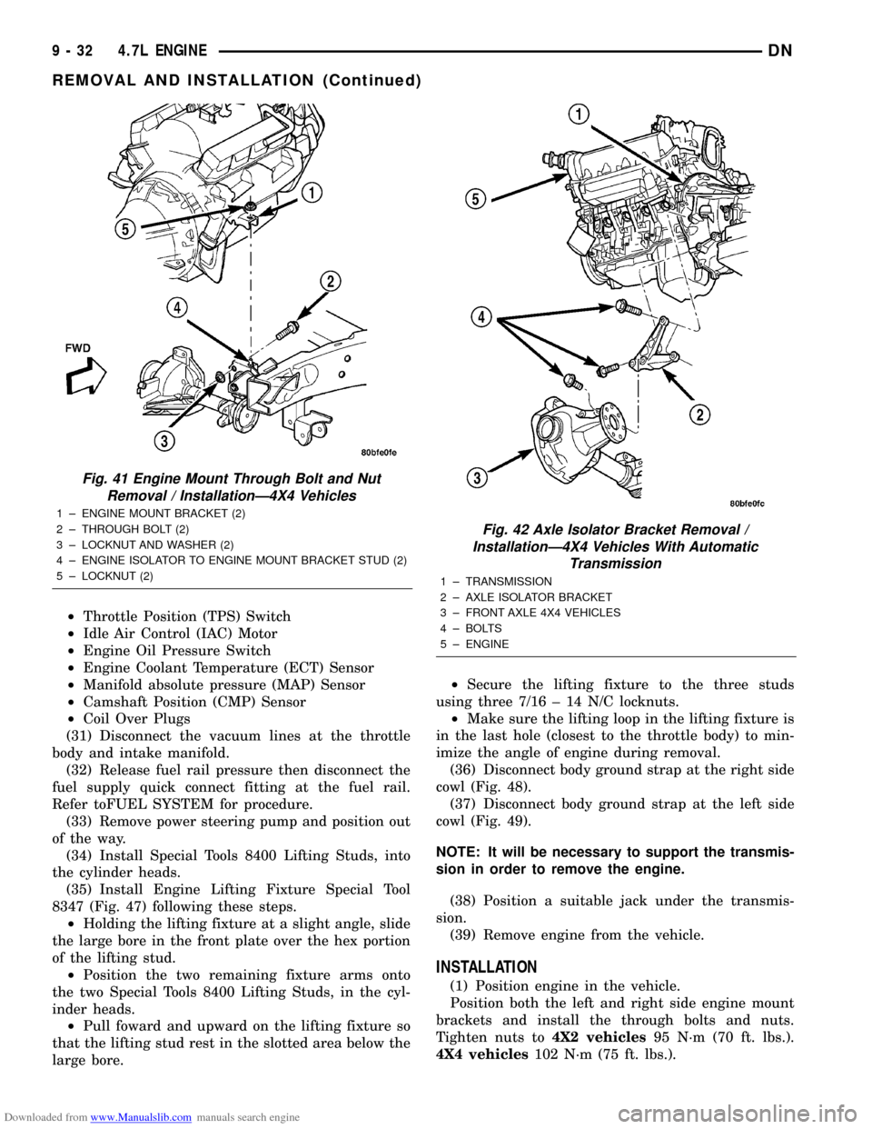
Fig. 41 Engine Mount Through Bolt and Nut
Removal / InstallationÐ4X4 Vehicles
1 ± ENGINE MOUNT BRACKET (2)
2 ± THROUGH BOLT (2)
3 ± LOCKNUT AND WASHER (2)
4 ± ENGINE ISOLATOR TO ENGINE MOUNT BRACKET STUD (2)
5 ± LOCKNUT (2)
Fig. 42 Axle Isolator Bracket Removal /
InstallationÐ4X4 Vehicles With Automatic
Transmission
1 ± TRANSMISSION
2 ± AXLE ISOLATOR BRACKET
3 ± FRONT AXLE 4X4 VEHICLES
4 ± BOLTS
5 ± ENGINE
9 - 32 4.7L ENGINEDN
REMOVAL AND INSTALLATION (Continued)
Page 33 of 193
Downloaded from www.Manualslib.com manuals search engine (2)4X4 vehiclesInstall locknuts onto the engine
mount brackets. Tighten locknuts to 41 N´m (30 ft.
lbs.).
(3) Remove jack from under the transmission.
(4) Remove Engine Lifting Fixture Special Tool
8347 (Fig. 47).
(5) Remove Special Tools 8400 Lifting Studs.
(6) Position generator wiring behind the oil dip-
stick tube, then install the oil dipstick tube upper
mounting bolt.
(7) Connect both left and right side body ground
straps.(8) Install power steering pump.
(9) Connect fuel supply line quick connect fitting.
(10) Connect the vacuum lines at the throttle body
and intake manifold.
(11) Connect engine harness at the following
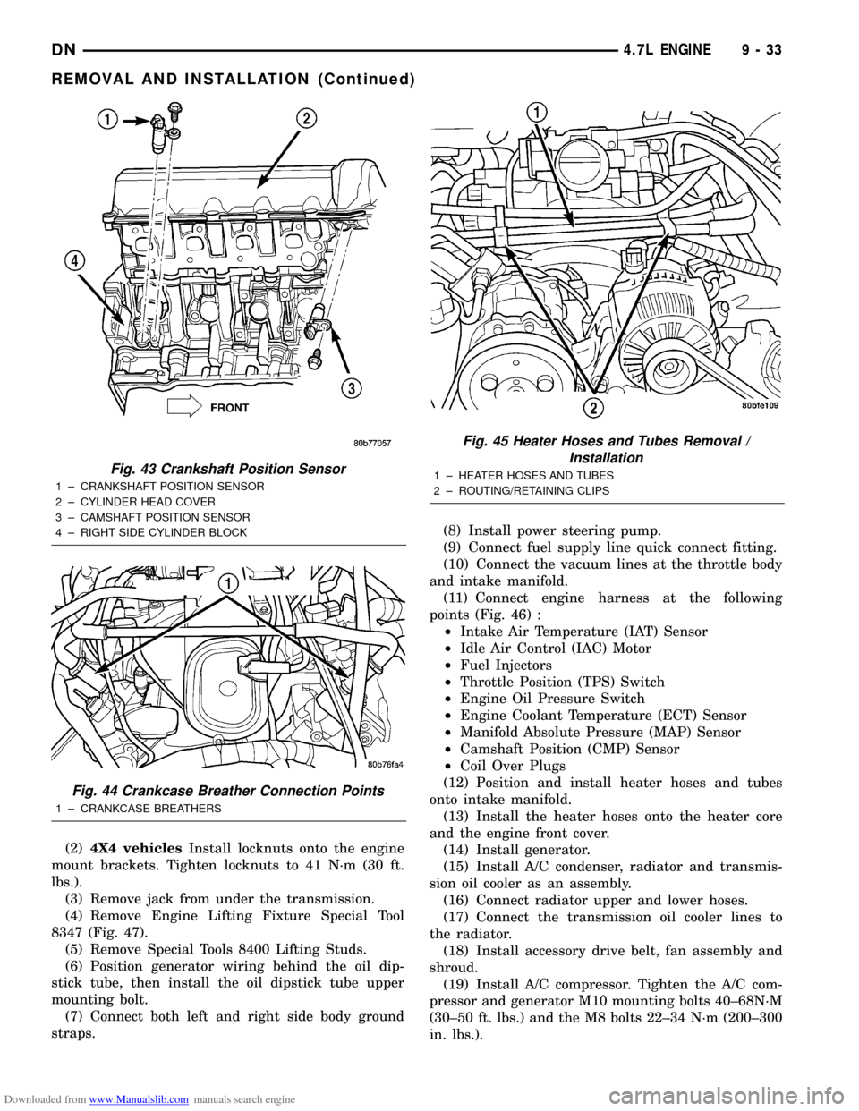
points (Fig. 46) :
²Intake Air Temperature (IAT) Sensor
²Idle Air Control (IAC) Motor
²Fuel Injectors
²Throttle Position (TPS) Switch
²Engine Oil Pressure Switch
²Engine Coolant Temperature (ECT) Sensor
²Manifold Absolute Pressure (MAP) Sensor
²Camshaft Position (CMP) Sensor
²Coil Over Plugs
(12) Position and install heater hoses and tubes
onto intake manifold.
(13) Install the heater hoses onto the heater core
and the engine front cover.
(14) Install generator.
(15) Install A/C condenser, radiator and transmis-
sion oil cooler as an assembly.
(16) Connect radiator upper and lower hoses.
(17) Connect the transmission oil cooler lines to
the radiator.
(18) Install accessory drive belt, fan assembly and
shroud.
(19) Install A/C compressor. Tighten the A/C com-
pressor and generator M10 mounting bolts 40±68N´M
(30±50 ft. lbs.) and the M8 bolts 22±34 N´m (200±300
in. lbs.).
Fig. 43 Crankshaft Position Sensor
1 ± CRANKSHAFT POSITION SENSOR
2 ± CYLINDER HEAD COVER
3 ± CAMSHAFT POSITION SENSOR
4 ± RIGHT SIDE CYLINDER BLOCK
Fig. 44 Crankcase Breather Connection Points
1 ± CRANKCASE BREATHERS
Fig. 45 Heater Hoses and Tubes Removal /
Installation
1 ± HEATER HOSES AND TUBES
2 ± ROUTING/RETAINING CLIPS
DN4.7L ENGINE 9 - 33
REMOVAL AND INSTALLATION (Continued)
Page 75 of 193
Downloaded from www.Manualslib.com manuals search engine NOTE: Once the oil pressure relief valve, cup plug,
and pin are removed, the pump assembly must be
replaced.
(3) If it is necessary to remove the pressure relief
valve, drive the roll pin from pump housing and
remove cup plug, spring and valve.
ASSEMBLE
(1) Wash all parts in a suitable solvent and inspect
carefully for damage or wear.
(2) Install inner and outer rotors
(3) Install oil pump cover plate and install cover
bolts and tighten them to 12 N´m (105 in. lbs.).
(4) Prime oil pump before installation by filling
rotor cavity with engine oil.
(5) If oil pressure is low and pump is within spec-
ifications, inspect for worn engine bearings or other
causes for oil pressure loss.
CLEANING AND INSPECTION
INTAKE MANIFOLD
CLEANING
NOTE: There is NO approved repair procedure for
the intake manifold. If severe damage is found dur-
ing inspection, the intake manifold must be
replaced.
Before installing the intake manifold thoroughly
clean the mating surfaces. Use a suitable cleaning
solvent, then air dry.
INSPECTION
(1) Inspect the intake sealing surface for cracks,
nicks and distortion.
(2) Inspect the intake manifold vacuum hose fit-
tings for looseness or blockage.
(3) Inspect the manifold to throttle body mating
surface for cracks, nicks and distortion.
EXHAUST MANIFOLD
CLEANING
(1) Clean the exhaust manifold using a suitable
cleaning solvent, then allow to air dry.
(2) Clean all gasket residue from the manifold
mating surface.
INSPECTION
(1) Inspect the exhaust manifold for cracks in the
mating surface and at every mounting bolt hole.
(2) Using a straight edge and a feeler gauge, check
the mating surface for warp and twist.(3) Inspect the manifold to exhaust pipe mating
surface for cracks, gouges, or other damage that
would prevent sealing.
CYLINDER HEADS
CLEANING
CYLINDER HEAD GASKET SURFACE PREPARATION
To ensure engine gasket sealing, proper surface
preparation must be performed, especially with the
use of aluminum engine components.
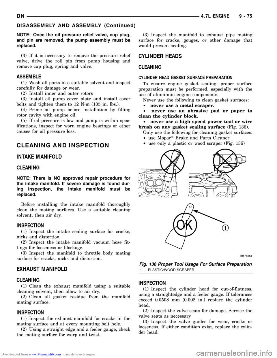
Never use the following to clean gasket surfaces:
²never use a metal scraper.
²never use an abrasive pad or paper to
clean the cylinder block.
²never use a high speed power tool or wire
brush on any gasket sealing surface(Fig. 136).
Only use the following for cleaning gasket surfaces:
²use MopartBrake and Parts Cleaner
²use only a plastic or wood scraper (Fig. 136)
INSPECTION
(1) Inspect the cylinder head for out-of-flatness,
using a straightedge and a feeler gauge. If tolerances
exceed 0.0508 mm (0.002 in.) replace the cylinder
head.
(2) Inspect the valve seats for damage. Service the
valve seats as necessary.
(3) Inspect the valve guides for wear, cracks or
looseness. If either condition exist, replace the cylin-
der head.
Fig. 136 Proper Tool Usage For Surface Preparation
1 ± PLASTIC/WOOD SCRAPER
DN4.7L ENGINE 9 - 75
DISASSEMBLY AND ASSEMBLY (Continued)
Page 102 of 193
Downloaded from www.Manualslib.com manuals search engine ENGINE MOUNTÐREAR
REMOVAL
(1) Disconnect the negative cable from the battery.
(2) Raise the vehicle on a hoist.
(3) Support the transmission with a transmission
jack.
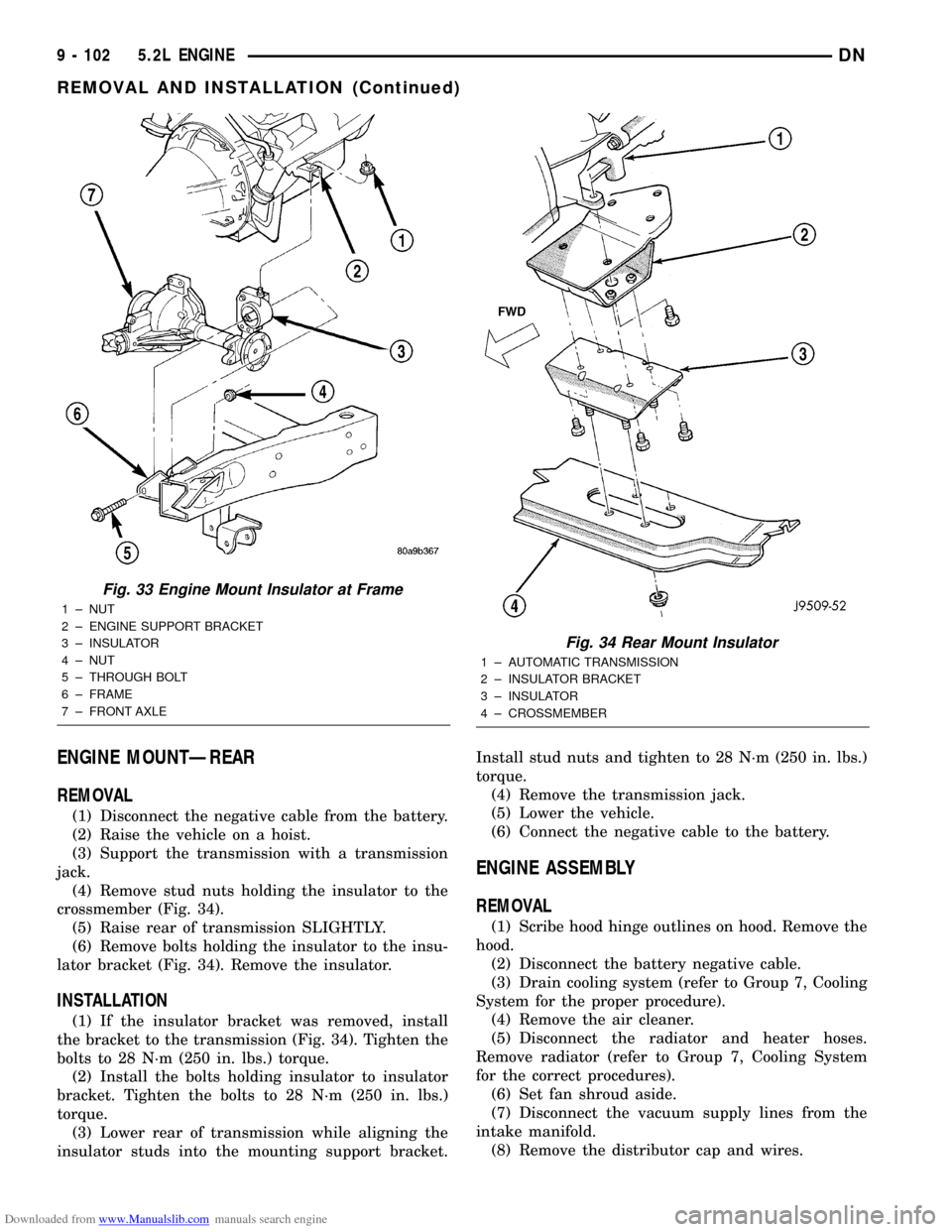
(4) Remove stud nuts holding the insulator to the
crossmember (Fig. 34).
(5) Raise rear of transmission SLIGHTLY.
(6) Remove bolts holding the insulator to the insu-
lator bracket (Fig. 34). Remove the insulator.
INSTALLATION
(1) If the insulator bracket was removed, install
the bracket to the transmission (Fig. 34). Tighten the
bolts to 28 N´m (250 in. lbs.) torque.
(2) Install the bolts holding insulator to insulator
bracket. Tighten the bolts to 28 N´m (250 in. lbs.)
torque.
(3) Lower rear of transmission while aligning the
insulator studs into the mounting support bracket.Install stud nuts and tighten to 28 N´m (250 in. lbs.)
torque.
(4) Remove the transmission jack.
(5) Lower the vehicle.
(6) Connect the negative cable to the battery.
ENGINE ASSEMBLY
REMOVAL
(1) Scribe hood hinge outlines on hood. Remove the
hood.
(2) Disconnect the battery negative cable.
(3) Drain cooling system (refer to Group 7, Cooling
System for the proper procedure).
(4) Remove the air cleaner.
(5) Disconnect the radiator and heater hoses.
Remove radiator (refer to Group 7, Cooling System
for the correct procedures).
(6) Set fan shroud aside.
(7) Disconnect the vacuum supply lines from the
intake manifold.
(8) Remove the distributor cap and wires.
Fig. 33 Engine Mount Insulator at Frame
1 ± NUT
2 ± ENGINE SUPPORT BRACKET
3 ± INSULATOR
4 ± NUT
5 ± THROUGH BOLT
6 ± FRAME
7 ± FRONT AXLE
Fig. 34 Rear Mount Insulator
1 ± AUTOMATIC TRANSMISSION
2 ± INSULATOR BRACKET
3 ± INSULATOR
4 ± CROSSMEMBER
9 - 102 5.2L ENGINEDN
REMOVAL AND INSTALLATION (Continued)
Page 103 of 193
Downloaded from www.Manualslib.com manuals search engine (9) Disconnect the accelerator linkage.
(10) Remove throttle body.
(11) Perform the Fuel System Pressure release
procedure (refer to Group 14, fuel System).
(12) Disconnect the fuel supply line.
(13) Disconnect the starter wires.
(14) Disconnect the oil pressure sending unit wire.
(15) Discharge the air conditioning system, if
equipped (refer to Group 24, Heating and Air Condi-
tioning for service procedures).
(16) Disconnect the air conditioning hoses.
(17) Disconnect the power steering hoses, if
equipped.
(18) Remove starter motor (refer to Group 8B, Bat-
tery/Starter/Generator Service).
(19) Remove the generator (refer to Group 8B, Bat-
tery/Starter/Generator Service).
(20) Raise and support the vehicle on a hoist.
(21) Disconnect exhaust pipe at manifold.
(22) Refer to Group 21, Transmissions for trans-
mission removal.
CAUTION: DO NOT lift the engine by the intake
manifold.
(23) Install an engine lifting fixture.
(24) The engine and front driving axle (engine/ax-
le/transmission) are connected through insulators
and support brackets. Separate the engine as follows:
²LEFT SIDEÐRemove 2 bolts attaching
(engine/pinion nose/transmission) bracket to trans-
mission bell housing. Remove 2 bracket to pinion
nose adaptor bolts. Separate engine from insulator by
removing upper nut washer assembly and bolt from
engine support bracket.
²RIGHT SIDEÐRemove 2 bracket to axle (dis-
connect housing) bolts and a bracket to bell housing
bolt. Separate engine from insulator by removing
upper nut washer assembly and bolt from engine
support bracket.
(25) Lower the vehicle.
(26) Install engine assembly on engine repair
stand.
INSTALLATION
(1) Remove engine from the repair stand and posi-
tion in the engine compartment.
(2) Install an engine support fixture.
(3) Raise and support the vehicle on a hoist.
(4) Install the engine front mounts.
(5) Refer to Group, 21 Transmissions for transmis-
sion installation
(6) Install the inspection plate.
(7) Remove transmission support.
(8) Install exhaust pipe to manifold.
(9) Lower the vehicle.
(10) Remove engine lifting fixture.(11) Install the generator (refer to Group 8B, Bat-
tery/Starter/Generator Service).
(12) Install starter motor (refer to Group 8B, Bat-
tery/Starter/Generator Service).
(13) Connect power steering hoses, if equipped.
(14) Connect air conditioning hoses.
(15) Evacuate and charge the air conditioning sys-
tem, if equipped (refer to Group 24, Heater and Air
Conditioning for service procedures).
(16) Using a new gasket, install throttle body.
Tighten the throttle body bolts to 23 N´m (200 in.
lbs.) torque.
(17) Connect the accelerator linkage.
(18) Connect the starter wires.
(19) Connect the oil pressure sending unit wire.
(20) Install the distributor cap and wiring.
(21) Connect the vacuum supply lines to the
intake manifold.
(22) Connect the fuel supply lines.
(23) Install the radiator (refer to Group 7, Cooling
System). Connect the radiator hoses and heater
hoses.
(24) Install fan shroud in position.
(25) Fill cooling system (refer to Group 7, Cooling
System for the proper procedure).
(26) Install the air cleaner.
(27) Install the battery.
(28) Warm engine and adjust.
(29) Install hood and line up with the scribe
marks.
(30) Road test vehicle.
INTAKE MANIFOLD
REMOVAL
(1) Disconnect the battery negative cable.
(2) Drain the cooling system. Refer to COOLING
SYSTEM.
(3) Remove the A/C compressor. Refer to HEAT-
ING and AIR CONDITIONING.
(4) Remove the generator. Refer to CHARGING
SYSTEM.
(5) Remove the accessory drive bracket.
(6) Remove the air cleaner assembly and air inlet
hose.
(7) Perform the fuel pressure release procedure.
Refer to FUEL SYSTEM.
(8) Disconnect the fuel supply line from the fuel
rail. Refer to FUEL SYSTEM.
(9) Disconnect the accelerator linkage and, if so
equipped, the speed control and transmission kick-
down cables.
(10) Remove the distributor cap and wires.
(11) Disconnect the coil wires.
(12) Disconnect the coolant temperature sending
unit wire.
DN5.2L ENGINE 9 - 103
REMOVAL AND INSTALLATION (Continued)
Page 144 of 193
Downloaded from www.Manualslib.com manuals search engine CONDITION POSSIBLE CAUSES CORRECTION
3. Worn or incorrectly gapped spark
plugs3. Replace or clean and re-gap spark plugs (Refer to
group 8D, Ignition System)
4. Worn or burned distributor rotor 4. Install new distributor rotor
5. Spark plug cables defective or
crossed5. Check for correct firing order or replace spark plug
cables. (Refer to Group 8D, Ignition System for
correct procedures.)
6. Faulty coil 6. Test and replace, if necessary (Refer to group 8D,
Ignition System)
7. Intake manifold vacuum leak 7. Inspect intake manifold gasket and vacuum hoses.
Replace if necessary
8. EGR valve leaking or stuck open 8. Test and replace, if necessary (Refer to group 25,
Emission Control Systems)
ENGINE MISSES
ON
ACCELERATION1. Worn or incorrectly gapped spark
plugs1. Replace spark plugs or clean and set gap. (Refer
to group 8D, Ignition System)
2. Spark plug cables defective or
crossed2. Replace or rewire secondary ignition cables. Refer
to Group 8D, Ignition System
3. Dirt in fuel system 3. Clean fuel system
4. Burned, warped or pitted valves 4. Install new valves
5. Faulty coil 5. Test and replace as necessary (refer to group 8D,
Ignition System)
MECHANICAL DIAGNOSIS CHARTÐGASOLINE ENGINES
CONDITION POSSIBLE CAUSES CORRECTION
NOISY VALVES/
LIFTERS1. High or low oil level
in crankcase1. Check for correct oil level. Adjust oil level by draining or adding
as needed
2. Thin or diluted oil 2. Change oil (Refer to Engine Oil Service in this group)
3. Low oil pressure 3. Check engine oil level. If ok, Perform oil pressure test. Refer to
this group for engine oil pressure test/specifications
4. Dirt in tappets/lash
adjusters4. Clean/replace hydraulic tappets/lash adjusters
5. Bent push rod(s) 5. Install new push rods
6. Worn rocker arms 6. Inspect oil supply to rocker arms and replace worn arms as
needed
7. Worn tappets/lash
adjusters7. Install new hydraulic tappets/lash adjusters
8. Worn valve guides 8. Inspect all valve guides and replace as necessary
9. Excessive runout of
valve seats or valve
faces9. Grind valves and seats
DN5.9L ENGINE 9 - 143
DIAGNOSIS AND TESTING (Continued)
Page 146 of 193
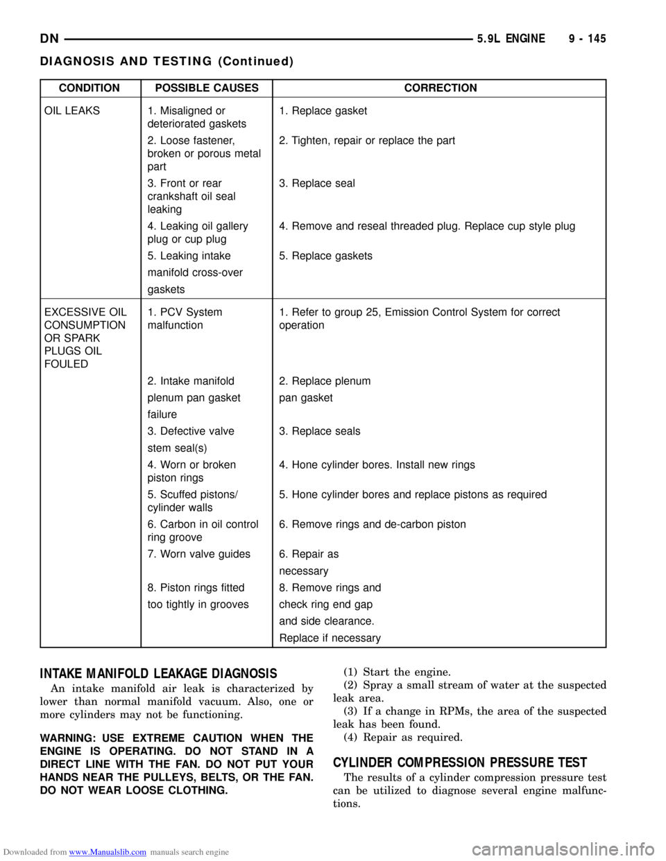
Downloaded from www.Manualslib.com manuals search engine CONDITION POSSIBLE CAUSES CORRECTION
OIL LEAKS 1. Misaligned or
deteriorated gaskets1. Replace gasket
2. Loose fastener,
broken or porous metal
part2. Tighten, repair or replace the part
3. Front or rear
crankshaft oil seal
leaking3. Replace seal
4. Leaking oil gallery
plug or cup plug4. Remove and reseal threaded plug. Replace cup style plug
5. Leaking intake 5. Replace gaskets
manifold cross-over
gaskets
EXCESSIVE OIL
CONSUMPTION
OR SPARK
PLUGS OIL
FOULED1. PCV System
malfunction1. Refer to group 25, Emission Control System for correct
operation
2. Intake manifold 2. Replace plenum
plenum pan gasket pan gasket
failure
3. Defective valve 3. Replace seals
stem seal(s)
4. Worn or broken
piston rings4. Hone cylinder bores. Install new rings
5. Scuffed pistons/
cylinder walls5. Hone cylinder bores and replace pistons as required
6. Carbon in oil control
ring groove6. Remove rings and de-carbon piston
7. Worn valve guides 6. Repair as
necessary
8. Piston rings fitted 8. Remove rings and
too tightly in grooves check ring end gap
and side clearance.
Replace if necessary
INTAKE MANIFOLD LEAKAGE DIAGNOSIS
An intake manifold air leak is characterized by
lower than normal manifold vacuum. Also, one or
more cylinders may not be functioning.
WARNING: USE EXTREME CAUTION WHEN THE
ENGINE IS OPERATING. DO NOT STAND IN A
DIRECT LINE WITH THE FAN. DO NOT PUT YOUR
HANDS NEAR THE PULLEYS, BELTS, OR THE FAN.
DO NOT WEAR LOOSE CLOTHING.(1) Start the engine.
(2) Spray a small stream of water at the suspected
leak area.
(3) If a change in RPMs, the area of the suspected
leak has been found.
(4) Repair as required.
CYLINDER COMPRESSION PRESSURE TEST
The results of a cylinder compression pressure test
can be utilized to diagnose several engine malfunc-
tions.
DN5.9L ENGINE 9 - 145
DIAGNOSIS AND TESTING (Continued)
Page 162 of 193
Downloaded from www.Manualslib.com manuals search engine REMOVALÐ4WD
(1) Disconnect the negative cable from the battery.
(2) Raise the vehicle on a hoist.
(3) Support the transmission with a transmission
jack.
(4) Remove stud nuts holding the insulator to the
crossmember (Fig. 39).
(5) Raise rear of transmission SLIGHTLY.
(6) Remove bolts holding the insulator to the insu-
lator bracket (Fig. 39). Remove the insulator.
INSTALLATIONÐ4WD
(1) If the insulator bracket was removed, install
the bracket to the transmission (Fig. 39). Tighten the
bolts to 28 N´m (250 in. lbs.) torque.
(2) Install the bolts holding insulator to insulator
bracket. Tighten the bolts to 28 N´m (250 in. lbs.)
torque.
(3) Lower rear of transmission while aligning the
insulator studs into the mounting support bracket.Install stud nuts and tighten to 28 N´m (250 in. lbs.)
torque.
(4) Remove the transmission jack.
(5) Lower the vehicle.
(6) Connect the negative cable to the battery.
ENGINE ASSEMBLY
REMOVAL
(1) Scribe hood hinge outlines on hood. Remove the
hood.
(2) Remove the battery.
(3) Drain cooling system. Refer to COOLING SYS-
TEM.
(4) Remove the air cleaner assembly and air inlet
hose.
(5) Disconnect the radiator and heater hoses.
(6) Set fan shroud aside.
(7) Remove the vacuum lines.
(8) Remove the distributor cap and wiring.
(9) Disconnect the accelerator linkage.
(10) Remove throttle body.
(11) Perform the Fuel System Pressure release
procedure Refer to FUEL SYSTEM.
(12) Disconnect the fuel lines.
(13) Disconnect the starter wires.
(14) Disconnect the oil pressure wire.
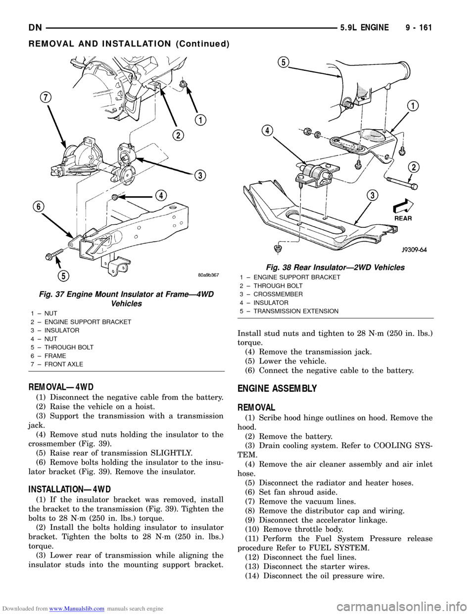
Fig. 37 Engine Mount Insulator at FrameÐ4WD
Vehicles
1 ± NUT
2 ± ENGINE SUPPORT BRACKET
3 ± INSULATOR
4 ± NUT
5 ± THROUGH BOLT
6 ± FRAME
7 ± FRONT AXLE
Fig. 38 Rear InsulatorÐ2WD Vehicles
1 ± ENGINE SUPPORT BRACKET
2 ± THROUGH BOLT
3 ± CROSSMEMBER
4 ± INSULATOR
5 ± TRANSMISSION EXTENSION
DN5.9L ENGINE 9 - 161
REMOVAL AND INSTALLATION (Continued)