compression ratio DODGE DURANGO 1998 1.G Workshop Manual
[x] Cancel search | Manufacturer: DODGE, Model Year: 1998, Model line: DURANGO, Model: DODGE DURANGO 1998 1.GPages: 193, PDF Size: 5.65 MB
Page 1 of 193
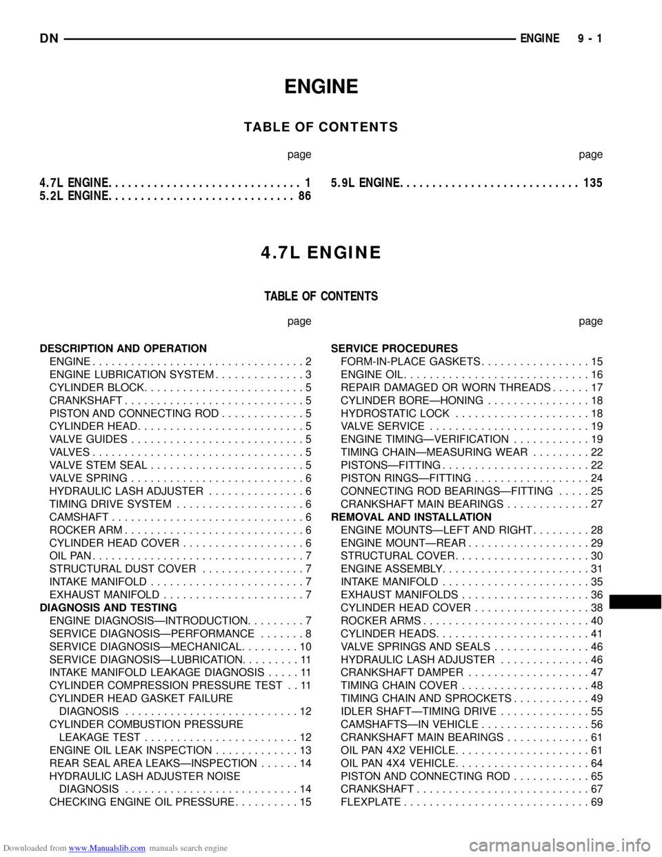
Downloaded from www.Manualslib.com manuals search engine ENGINE
TABLE OF CONTENTS
page page
4.7L ENGINE.............................. 1
5.2L ENGINE............................. 865.9L ENGINE............................ 135
4.7L ENGINE
TABLE OF CONTENTS
page page
DESCRIPTION AND OPERATION
ENGINE.................................2
ENGINE LUBRICATION SYSTEM..............3
CYLINDER BLOCK.........................5
CRANKSHAFT............................5
PISTON AND CONNECTING ROD.............5
CYLINDER HEAD..........................5
VALVE GUIDES...........................5
VALVES.................................5
VALVE STEM SEAL........................5
VALVE SPRING...........................6
HYDRAULIC LASH ADJUSTER...............6
TIMING DRIVE SYSTEM....................6
CAMSHAFT..............................6
ROCKER ARM............................6
CYLINDER HEAD COVER...................6
OILPAN.................................7
STRUCTURAL DUST COVER................7
INTAKE MANIFOLD........................7
EXHAUST MANIFOLD......................7
DIAGNOSIS AND TESTING
ENGINE DIAGNOSISÐINTRODUCTION.........7
SERVICE DIAGNOSISÐPERFORMANCE.......8
SERVICE DIAGNOSISÐMECHANICAL.........10
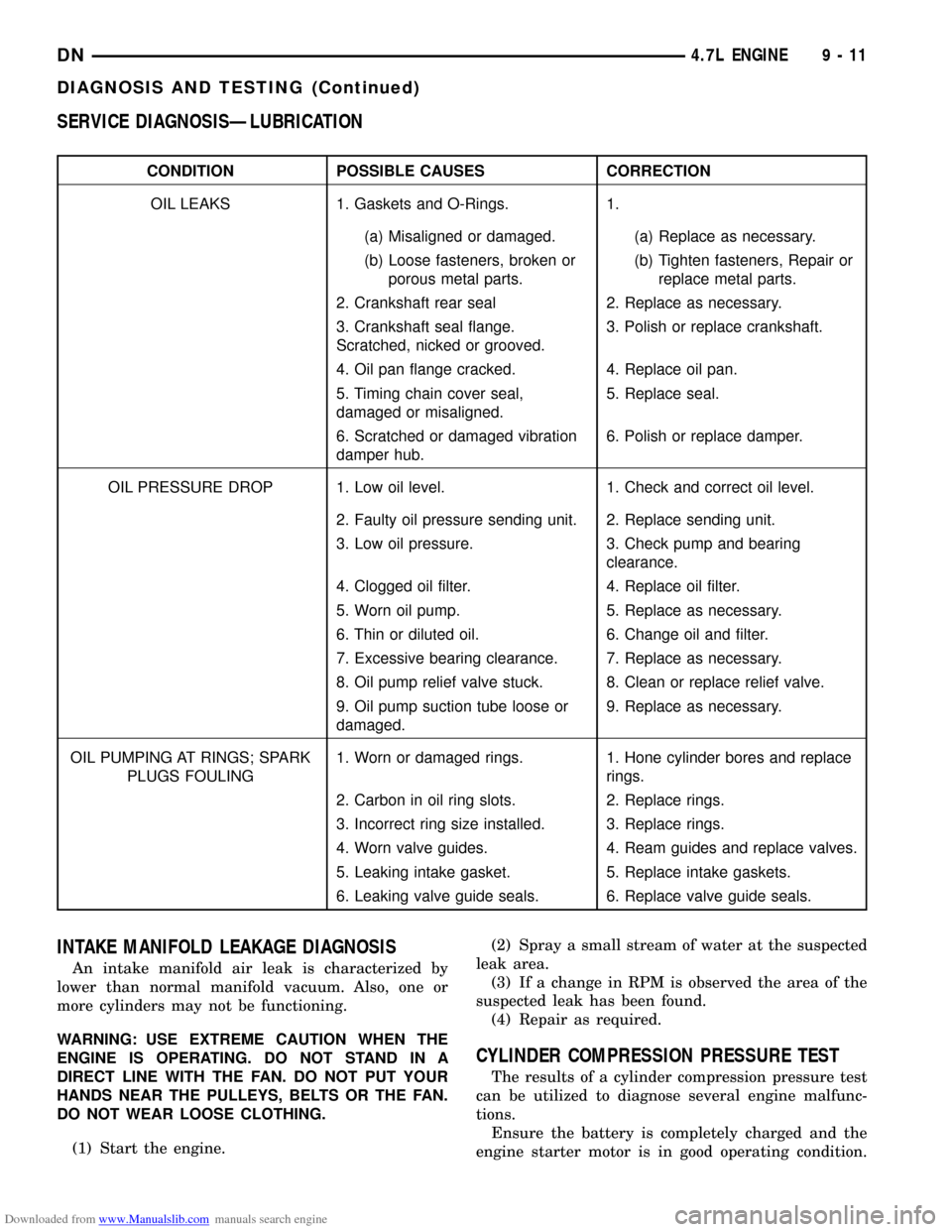
SERVICE DIAGNOSISÐLUBRICATION.........11
INTAKE MANIFOLD LEAKAGE DIAGNOSIS.....11
CYLINDER COMPRESSION PRESSURE TEST . . 11
CYLINDER HEAD GASKET FAILURE
DIAGNOSIS...........................12
CYLINDER COMBUSTION PRESSURE
LEAKAGE TEST........................12
ENGINE OIL LEAK INSPECTION.............13
REAR SEAL AREA LEAKSÐINSPECTION......14
HYDRAULIC LASH ADJUSTER NOISE
DIAGNOSIS...........................14
CHECKING ENGINE OIL PRESSURE..........15SERVICE PROCEDURES
FORM-IN-PLACE GASKETS.................15
ENGINE OIL.............................16
REPAIR DAMAGED OR WORN THREADS......17
CYLINDER BOREÐHONING................18
HYDROSTATIC LOCK.....................18
VALVE SERVICE.........................19
ENGINE TIMINGÐVERIFICATION............19
TIMING CHAINÐMEASURING WEAR.........22
PISTONSÐFITTING.......................22
PISTON RINGSÐFITTING..................24
CONNECTING ROD BEARINGSÐFITTING.....25
CRANKSHAFT MAIN BEARINGS.............27
REMOVAL AND INSTALLATION
ENGINE MOUNTSÐLEFT AND RIGHT.........28
ENGINE MOUNTÐREAR...................29
STRUCTURAL COVER.....................30
ENGINE ASSEMBLY.......................31
INTAKE MANIFOLD.......................35
EXHAUST MANIFOLDS....................36
CYLINDER HEAD COVER..................38
ROCKER ARMS..........................40
CYLINDER HEADS........................41
VALVE SPRINGS AND SEALS...............46
HYDRAULIC LASH ADJUSTER..............46
CRANKSHAFT DAMPER...................47
TIMING CHAIN COVER....................48
TIMING CHAIN AND SPROCKETS............49
IDLER SHAFTÐTIMING DRIVE..............55
CAMSHAFTSÐIN VEHICLE.................56
CRANKSHAFT MAIN BEARINGS.............61
OIL PAN 4X2 VEHICLE.....................61
OIL PAN 4X4 VEHICLE.....................64
PISTON AND CONNECTING ROD............65
CRANKSHAFT...........................67
FLEXPLATE.............................69
DNENGINE 9 - 1
Page 7 of 193
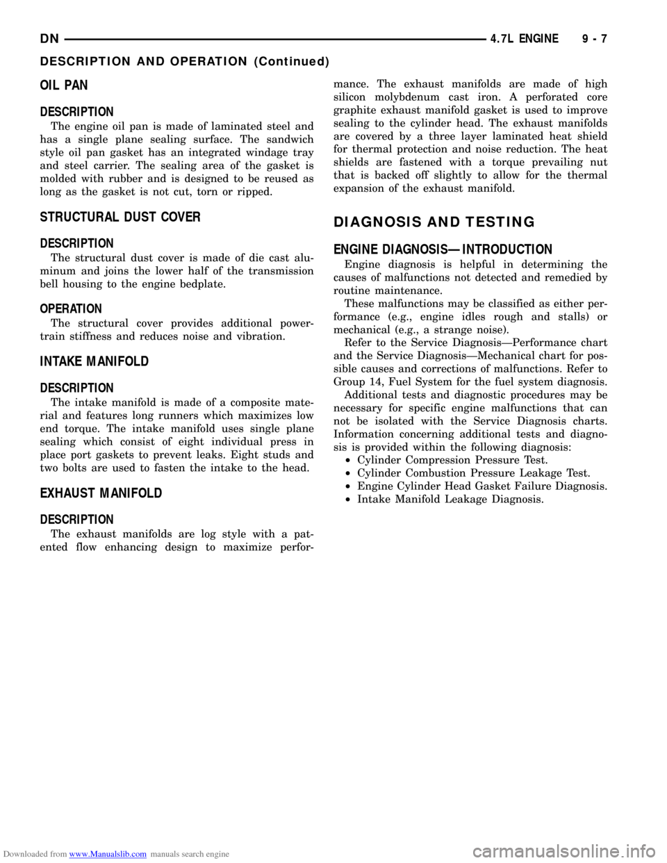
Downloaded from www.Manualslib.com manuals search engine OIL PAN
DESCRIPTION
The engine oil pan is made of laminated steel and
has a single plane sealing surface. The sandwich
style oil pan gasket has an integrated windage tray
and steel carrier. The sealing area of the gasket is
molded with rubber and is designed to be reused as
long as the gasket is not cut, torn or ripped.
STRUCTURAL DUST COVER
DESCRIPTION
The structural dust cover is made of die cast alu-
minum and joins the lower half of the transmission
bell housing to the engine bedplate.
OPERATION
The structural cover provides additional power-
train stiffness and reduces noise and vibration.
INTAKE MANIFOLD
DESCRIPTION
The intake manifold is made of a composite mate-
rial and features long runners which maximizes low
end torque. The intake manifold uses single plane
sealing which consist of eight individual press in
place port gaskets to prevent leaks. Eight studs and
two bolts are used to fasten the intake to the head.
EXHAUST MANIFOLD
DESCRIPTION
The exhaust manifolds are log style with a pat-
ented flow enhancing design to maximize perfor-mance. The exhaust manifolds are made of high
silicon molybdenum cast iron. A perforated core
graphite exhaust manifold gasket is used to improve
sealing to the cylinder head. The exhaust manifolds
are covered by a three layer laminated heat shield
for thermal protection and noise reduction. The heat
shields are fastened with a torque prevailing nut
that is backed off slightly to allow for the thermal
expansion of the exhaust manifold.
DIAGNOSIS AND TESTING
ENGINE DIAGNOSISÐINTRODUCTION
Engine diagnosis is helpful in determining the
causes of malfunctions not detected and remedied by
routine maintenance.
These malfunctions may be classified as either per-
formance (e.g., engine idles rough and stalls) or
mechanical (e.g., a strange noise).
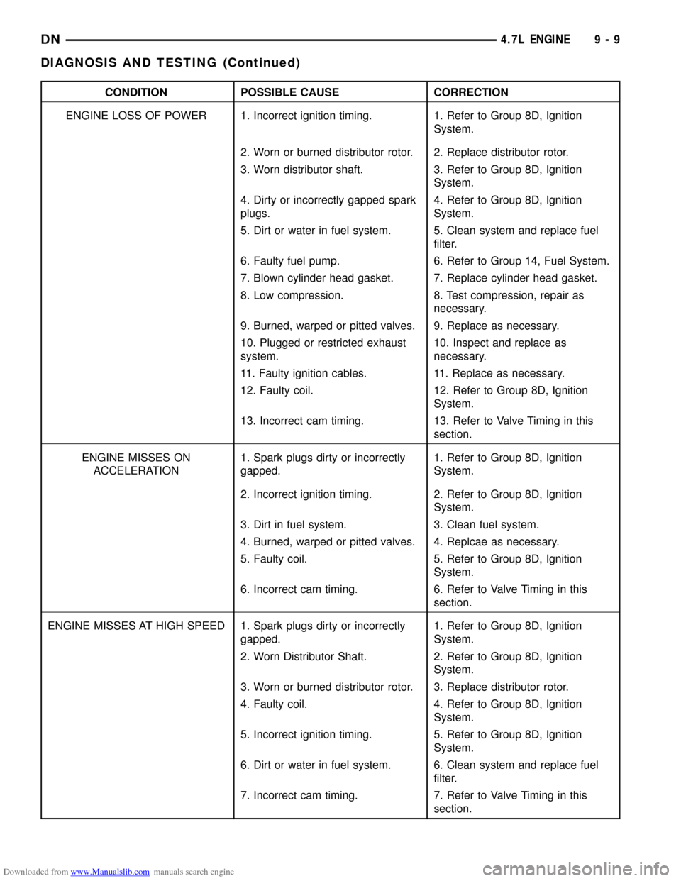
Refer to the Service DiagnosisÐPerformance chart
and the Service DiagnosisÐMechanical chart for pos-
sible causes and corrections of malfunctions. Refer to
Group 14, Fuel System for the fuel system diagnosis.
Additional tests and diagnostic procedures may be
necessary for specific engine malfunctions that can
not be isolated with the Service Diagnosis charts.
Information concerning additional tests and diagno-
sis is provided within the following diagnosis:
²Cylinder Compression Pressure Test.
²Cylinder Combustion Pressure Leakage Test.
²Engine Cylinder Head Gasket Failure Diagnosis.
²Intake Manifold Leakage Diagnosis.
DN4.7L ENGINE 9 - 7
DESCRIPTION AND OPERATION (Continued)
Page 9 of 193
Downloaded from www.Manualslib.com manuals search engine CONDITION POSSIBLE CAUSE CORRECTION
ENGINE LOSS OF POWER 1. Incorrect ignition timing. 1. Refer to Group 8D, Ignition
System.
2. Worn or burned distributor rotor. 2. Replace distributor rotor.
3. Worn distributor shaft. 3. Refer to Group 8D, Ignition
System.
4. Dirty or incorrectly gapped spark
plugs.4. Refer to Group 8D, Ignition
System.
5. Dirt or water in fuel system. 5. Clean system and replace fuel
filter.
6. Faulty fuel pump. 6. Refer to Group 14, Fuel System.
7. Blown cylinder head gasket. 7. Replace cylinder head gasket.
8. Low compression. 8. Test compression, repair as
necessary.
9. Burned, warped or pitted valves. 9. Replace as necessary.
10. Plugged or restricted exhaust
system.10. Inspect and replace as
necessary.
11. Faulty ignition cables. 11. Replace as necessary.
12. Faulty coil. 12. Refer to Group 8D, Ignition
System.
13. Incorrect cam timing. 13. Refer to Valve Timing in this
section.
ENGINE MISSES ON
ACCELERATION1. Spark plugs dirty or incorrectly
gapped.1. Refer to Group 8D, Ignition
System.
2. Incorrect ignition timing. 2. Refer to Group 8D, Ignition
System.
3. Dirt in fuel system. 3. Clean fuel system.
4. Burned, warped or pitted valves. 4. Replcae as necessary.
5. Faulty coil. 5. Refer to Group 8D, Ignition
System.
6. Incorrect cam timing. 6. Refer to Valve Timing in this
section.
ENGINE MISSES AT HIGH SPEED 1. Spark plugs dirty or incorrectly
gapped.1. Refer to Group 8D, Ignition
System.
2. Worn Distributor Shaft. 2. Refer to Group 8D, Ignition
System.
3. Worn or burned distributor rotor. 3. Replace distributor rotor.
4. Faulty coil. 4. Refer to Group 8D, Ignition
System.
5. Incorrect ignition timing. 5. Refer to Group 8D, Ignition
System.
6. Dirt or water in fuel system. 6. Clean system and replace fuel
filter.
7. Incorrect cam timing. 7. Refer to Valve Timing in this
section.
DN4.7L ENGINE 9 - 9
DIAGNOSIS AND TESTING (Continued)
Page 11 of 193
Downloaded from www.Manualslib.com manuals search engine SERVICE DIAGNOSISÐLUBRICATION
CONDITION POSSIBLE CAUSES CORRECTION
OIL LEAKS 1. Gaskets and O-Rings. 1.
(a) Misaligned or damaged. (a) Replace as necessary.
(b) Loose fasteners, broken or
porous metal parts.(b) Tighten fasteners, Repair or
replace metal parts.
2. Crankshaft rear seal 2. Replace as necessary.
3. Crankshaft seal flange.
Scratched, nicked or grooved.3. Polish or replace crankshaft.
4. Oil pan flange cracked. 4. Replace oil pan.
5. Timing chain cover seal,
damaged or misaligned.5. Replace seal.
6. Scratched or damaged vibration
damper hub.6. Polish or replace damper.
OIL PRESSURE DROP 1. Low oil level. 1. Check and correct oil level.
2. Faulty oil pressure sending unit. 2. Replace sending unit.
3. Low oil pressure. 3. Check pump and bearing
clearance.
4. Clogged oil filter. 4. Replace oil filter.
5. Worn oil pump. 5. Replace as necessary.
6. Thin or diluted oil. 6. Change oil and filter.
7. Excessive bearing clearance. 7. Replace as necessary.
8. Oil pump relief valve stuck. 8. Clean or replace relief valve.
9. Oil pump suction tube loose or
damaged.9. Replace as necessary.
OIL PUMPING AT RINGS; SPARK
PLUGS FOULING1. Worn or damaged rings. 1. Hone cylinder bores and replace
rings.
2. Carbon in oil ring slots. 2. Replace rings.
3. Incorrect ring size installed. 3. Replace rings.
4. Worn valve guides. 4. Ream guides and replace valves.
5. Leaking intake gasket. 5. Replace intake gaskets.
6. Leaking valve guide seals. 6. Replace valve guide seals.
INTAKE MANIFOLD LEAKAGE DIAGNOSIS
An intake manifold air leak is characterized by
lower than normal manifold vacuum. Also, one or
more cylinders may not be functioning.
WARNING: USE EXTREME CAUTION WHEN THE
ENGINE IS OPERATING. DO NOT STAND IN A
DIRECT LINE WITH THE FAN. DO NOT PUT YOUR
HANDS NEAR THE PULLEYS, BELTS OR THE FAN.
DO NOT WEAR LOOSE CLOTHING.
(1) Start the engine.(2) Spray a small stream of water at the suspected
leak area.
(3) If a change in RPM is observed the area of the
suspected leak has been found.
(4) Repair as required.
CYLINDER COMPRESSION PRESSURE TEST
The results of a cylinder compression pressure test
can be utilized to diagnose several engine malfunc-
tions.
Ensure the battery is completely charged and the
engine starter motor is in good operating condition.
DN4.7L ENGINE 9 - 11
DIAGNOSIS AND TESTING (Continued)
Page 12 of 193
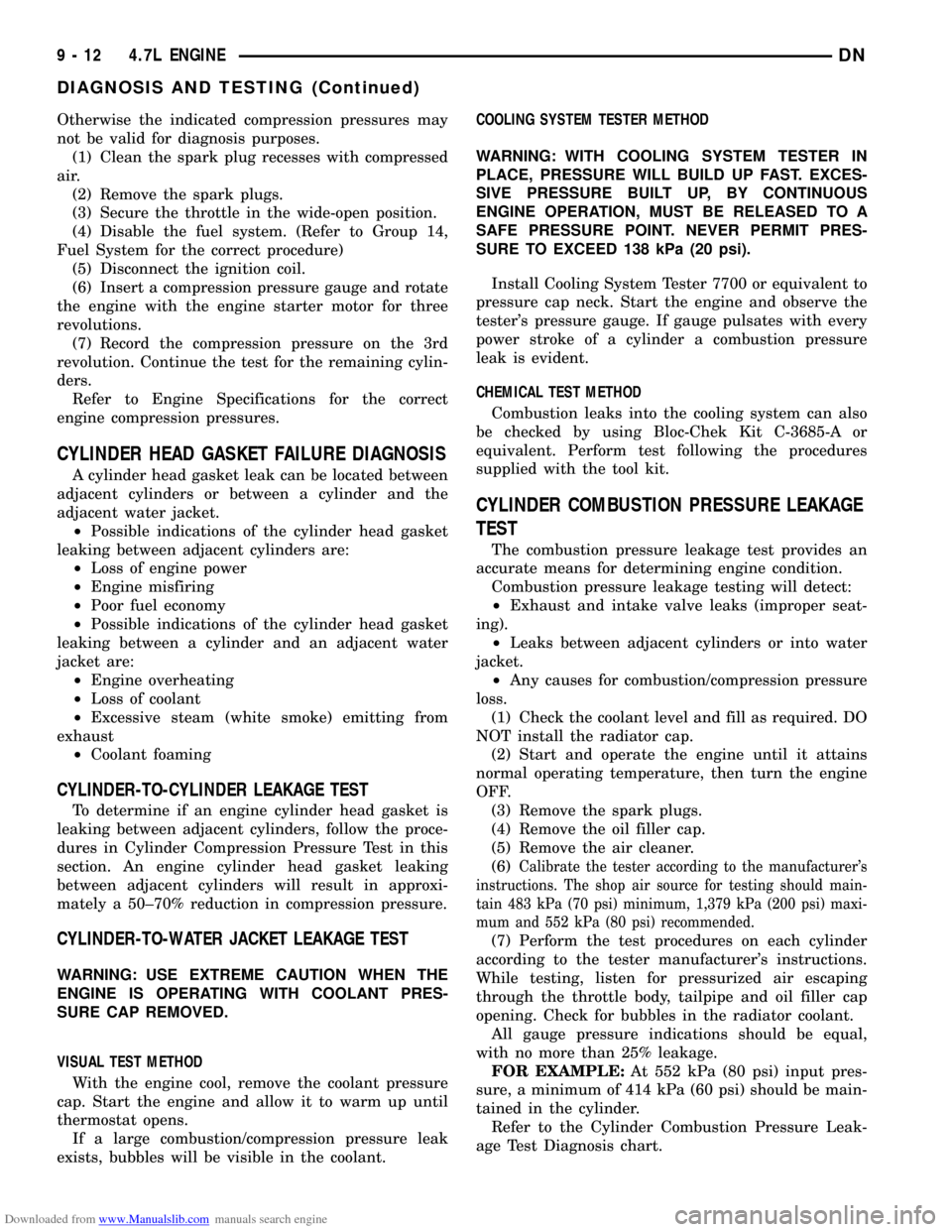
Downloaded from www.Manualslib.com manuals search engine Otherwise the indicated compression pressures may
not be valid for diagnosis purposes.
(1) Clean the spark plug recesses with compressed
air.
(2) Remove the spark plugs.
(3) Secure the throttle in the wide-open position.
(4) Disable the fuel system. (Refer to Group 14,
Fuel System for the correct procedure)
(5) Disconnect the ignition coil.
(6) Insert a compression pressure gauge and rotate
the engine with the engine starter motor for three
revolutions.
(7) Record the compression pressure on the 3rd
revolution. Continue the test for the remaining cylin-
ders.
Refer to Engine Specifications for the correct
engine compression pressures.
CYLINDER HEAD GASKET FAILURE DIAGNOSIS
A cylinder head gasket leak can be located between
adjacent cylinders or between a cylinder and the
adjacent water jacket.
²Possible indications of the cylinder head gasket
leaking between adjacent cylinders are:
²Loss of engine power
²Engine misfiring
²Poor fuel economy
²Possible indications of the cylinder head gasket
leaking between a cylinder and an adjacent water
jacket are:
²Engine overheating
²Loss of coolant
²Excessive steam (white smoke) emitting from
exhaust
²Coolant foaming
CYLINDER-TO-CYLINDER LEAKAGE TEST
To determine if an engine cylinder head gasket is
leaking between adjacent cylinders, follow the proce-
dures in Cylinder Compression Pressure Test in this
section. An engine cylinder head gasket leaking
between adjacent cylinders will result in approxi-
mately a 50±70% reduction in compression pressure.
CYLINDER-TO-WATER JACKET LEAKAGE TEST
WARNING: USE EXTREME CAUTION WHEN THE
ENGINE IS OPERATING WITH COOLANT PRES-
SURE CAP REMOVED.
VISUAL TEST METHOD
With the engine cool, remove the coolant pressure
cap. Start the engine and allow it to warm up until
thermostat opens.
If a large combustion/compression pressure leak
exists, bubbles will be visible in the coolant.COOLING SYSTEM TESTER METHOD
WARNING: WITH COOLING SYSTEM TESTER IN
PLACE, PRESSURE WILL BUILD UP FAST. EXCES-
SIVE PRESSURE BUILT UP, BY CONTINUOUS
ENGINE OPERATION, MUST BE RELEASED TO A
SAFE PRESSURE POINT. NEVER PERMIT PRES-
SURE TO EXCEED 138 kPa (20 psi).
Install Cooling System Tester 7700 or equivalent to
pressure cap neck. Start the engine and observe the
tester's pressure gauge. If gauge pulsates with every
power stroke of a cylinder a combustion pressure
leak is evident.
CHEMICAL TEST METHOD
Combustion leaks into the cooling system can also
be checked by using Bloc-Chek Kit C-3685-A or
equivalent. Perform test following the procedures
supplied with the tool kit.
CYLINDER COMBUSTION PRESSURE LEAKAGE
TEST
The combustion pressure leakage test provides an
accurate means for determining engine condition.
Combustion pressure leakage testing will detect:
²Exhaust and intake valve leaks (improper seat-
ing).
²Leaks between adjacent cylinders or into water
jacket.
²Any causes for combustion/compression pressure
loss.
(1) Check the coolant level and fill as required. DO
NOT install the radiator cap.
(2) Start and operate the engine until it attains
normal operating temperature, then turn the engine
OFF.
(3) Remove the spark plugs.
(4) Remove the oil filler cap.
(5) Remove the air cleaner.
(6)
Calibrate the tester according to the manufacturer's
instructions. The shop air source for testing should main-
tain 483 kPa (70 psi) minimum, 1,379 kPa (200 psi) maxi-
mum and 552 kPa (80 psi) recommended.
(7) Perform the test procedures on each cylinder
according to the tester manufacturer's instructions.
While testing, listen for pressurized air escaping
through the throttle body, tailpipe and oil filler cap
opening. Check for bubbles in the radiator coolant.
All gauge pressure indications should be equal,
with no more than 25% leakage.
FOR EXAMPLE:At 552 kPa (80 psi) input pres-
sure, a minimum of 414 kPa (60 psi) should be main-
tained in the cylinder.
Refer to the Cylinder Combustion Pressure Leak-
age Test Diagnosis chart.
9 - 12 4.7L ENGINEDN
DIAGNOSIS AND TESTING (Continued)
Page 78 of 193
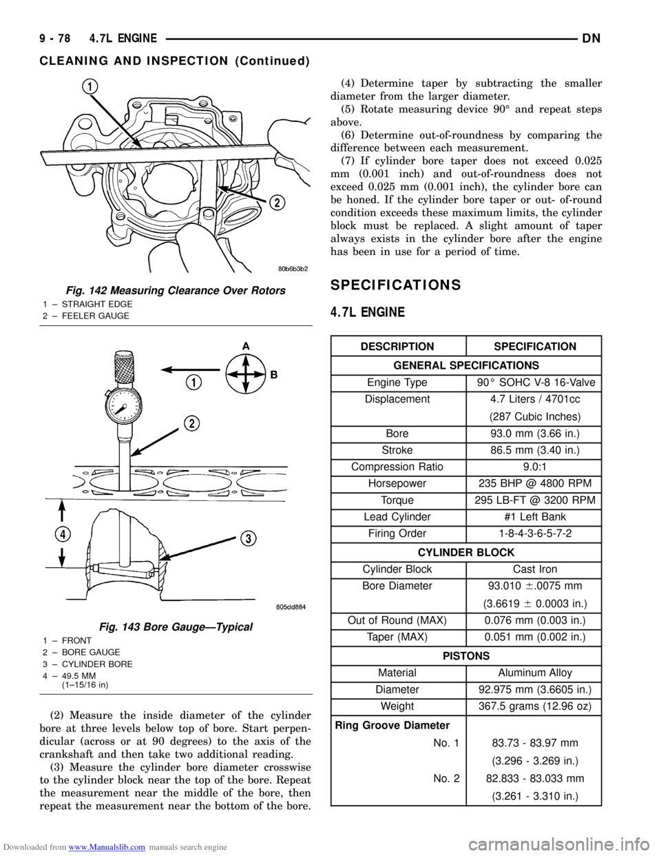
Downloaded from www.Manualslib.com manuals search engine (2) Measure the inside diameter of the cylinder
bore at three levels below top of bore. Start perpen-
dicular (across or at 90 degrees) to the axis of the
crankshaft and then take two additional reading.
(3) Measure the cylinder bore diameter crosswise
to the cylinder block near the top of the bore. Repeat
the measurement near the middle of the bore, then
repeat the measurement near the bottom of the bore.(4) Determine taper by subtracting the smaller
diameter from the larger diameter.
(5) Rotate measuring device 90É and repeat steps
above.
(6) Determine out-of-roundness by comparing the
difference between each measurement.
(7) If cylinder bore taper does not exceed 0.025
mm (0.001 inch) and out-of-roundness does not
exceed 0.025 mm (0.001 inch), the cylinder bore can
be honed. If the cylinder bore taper or out- of-round
condition exceeds these maximum limits, the cylinder
block must be replaced. A slight amount of taper
always exists in the cylinder bore after the engine
has been in use for a period of time.
SPECIFICATIONS
4.7L ENGINE
DESCRIPTION SPECIFICATION
GENERAL SPECIFICATIONS
Engine Type 90É SOHC V-8 16-Valve
Displacement 4.7 Liters / 4701cc
(287 Cubic Inches)
Bore 93.0 mm (3.66 in.)
Stroke 86.5 mm (3.40 in.)
Compression Ratio 9.0:1
Horsepower 235 BHP @ 4800 RPM
Torque 295 LB-FT @ 3200 RPM
Lead Cylinder #1 Left Bank
Firing Order 1-8-4-3-6-5-7-2
CYLINDER BLOCK
Cylinder Block Cast Iron
Bore Diameter 93.0106.0075 mm
(3.661960.0003 in.)
Out of Round (MAX) 0.076 mm (0.003 in.)
Taper (MAX) 0.051 mm (0.002 in.)
PISTONS
Material Aluminum Alloy
Diameter 92.975 mm (3.6605 in.)
Weight 367.5 grams (12.96 oz)
Ring Groove Diameter
No. 1 83.73 - 83.97 mm
(3.296 - 3.269 in.)
No. 2 82.833 - 83.033 mm
(3.261 - 3.310 in.)
Fig. 142 Measuring Clearance Over Rotors
1 ± STRAIGHT EDGE
2 ± FEELER GAUGE
Fig. 143 Bore GaugeÐTypical
1 ± FRONT
2 ± BORE GAUGE
3 ± CYLINDER BORE
4 ± 49.5 MM
(1±15/16 in)
9 - 78 4.7L ENGINEDN
CLEANING AND INSPECTION (Continued)
Page 79 of 193
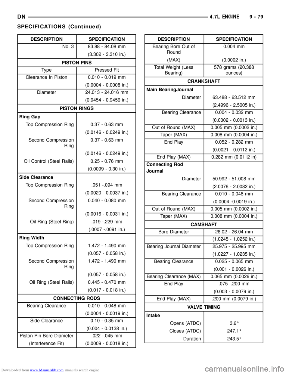
Downloaded from www.Manualslib.com manuals search engine DESCRIPTION SPECIFICATION
No. 3 83.88 - 84.08 mm
(3.302 - 3.310 in.)
PISTON PINS
Type Pressed Fit
Clearance In Piston 0.010 - 0.019 mm
(0.0004 - 0.0008 in.)
Diameter 24.013 - 24.016 mm
(0.9454 - 0.9456 in.)
PISTON RINGS
Ring Gap
Top Compression Ring 0.37 - 0.63 mm
(0.0146 - 0.0249 in.)
Second Compression
Ring0.37 - 0.63 mm
(0.0146 - 0.0249 in.)
Oil Control (Steel Rails) 0.25 - 0.76 mm
(0.0099 - 0.30 in.)
Side Clearance
Top Compression Ring .051 -.094 mm
(0.0020 - 0.0037 in.)
Second Compression
Ring0.040 - 0.080 mm
(0.0016 - 0.0031 in.)
Oil Ring (Steel Ring) .019 -.229 mm
(.0007 -.0091 in.)
Ring Width
Top Compression Ring 1.472 - 1.490 mm
(0.057 - 0.058 in.)
Second Compression
Ring1.472 - 1.490 mm
(0.057 - 0.058 in.)
Oil Ring (Steel Rails) 0.445 - 0.470 mm
(0.017 - 0.018 in.)
CONNECTING RODS
Bearing Clearance 0.010 - 0.048 mm
(0.0004 - 0.0019 in.)
Side Clearance 0.10 - 0.35 mm
(0.004 - 0.0138 in.)
Piston Pin Bore Diameter .022 -.045 mm
(Interference Fit) (0.0009 - 0.0018 in.)DESCRIPTION SPECIFICATION
Bearing Bore Out of
Round0.004 mm
(MAX) (0.0002 in.)
Total Weight (Less
Bearing)578 grams (20.388
ounces)
CRANKSHAFT
Main BearingJournal
Diameter 63.488 - 63.512 mm
(2.4996 - 2.5005 in.)
Bearing Clearance 0.004 - 0.032 mm
(0.0002 - 0.0013 in.)
Out of Round (MAX) 0.005 mm (0.0002 in.)
Taper (MAX) 0.008 mm (0.0004 in.)
End Play 0.052 - 0.282 mm
(0.0021 - 0.0112 in.)
End Play (MAX) 0.282 mm (0.0112 in)
Connecting Rod
Journal
Diameter 50.992 - 51.008 mm
(2.0076 - 2.0082 in.)
Bearing Clearance 0.010 - 0.048 mm
(0.0004 -0.0019 in.)
Out of Round (MAX) 0.005 mm (0.0002 in.)
Taper (MAX) 0.008 mm (0.0004 in.)
CAMSHAFT
Bore Diameter 26.02 - 26.04 mm
(1.0245 - 1.0252 in.)
Bearing Journal Diameter 25.975 - 25.995 mm
(1.0227 - 1.0235 in.)
Bearing Clearance 0.025 - 0.065 mm
(0.001 - 0.0026 in.)
Bearing Clearance (MAX) 0.065 mm (0.0026 in.)
End Play .075 -.200 mm
(0.003 - 0.0079 in.)
End Play (MAX) .200 mm (0.0079 in.)
VALVE TIMING
Intake
Opens (ATDC) 3.6É
Closes (ATDC) 247.1É
Duration 243.5É
DN4.7L ENGINE 9 - 79
SPECIFICATIONS (Continued)
Page 107 of 193
Downloaded from www.Manualslib.com manuals search engine (2) Position the cylinder head cover onto the gas-
ket. Tighten the bolts to 11 N´m (95 in. lbs.) torque.
(3) Install closed crankcase ventilation system and
evaporation control system.
(4) Install the air inlet hose.
(5) Connect the negative cable to the battery.
ROCKER ARMS AND PUSH RODS
REMOVAL
(1) Remove cylinder head cover and gasket. Refer
to Cylinder Head Cover in this section for correct
procedure.
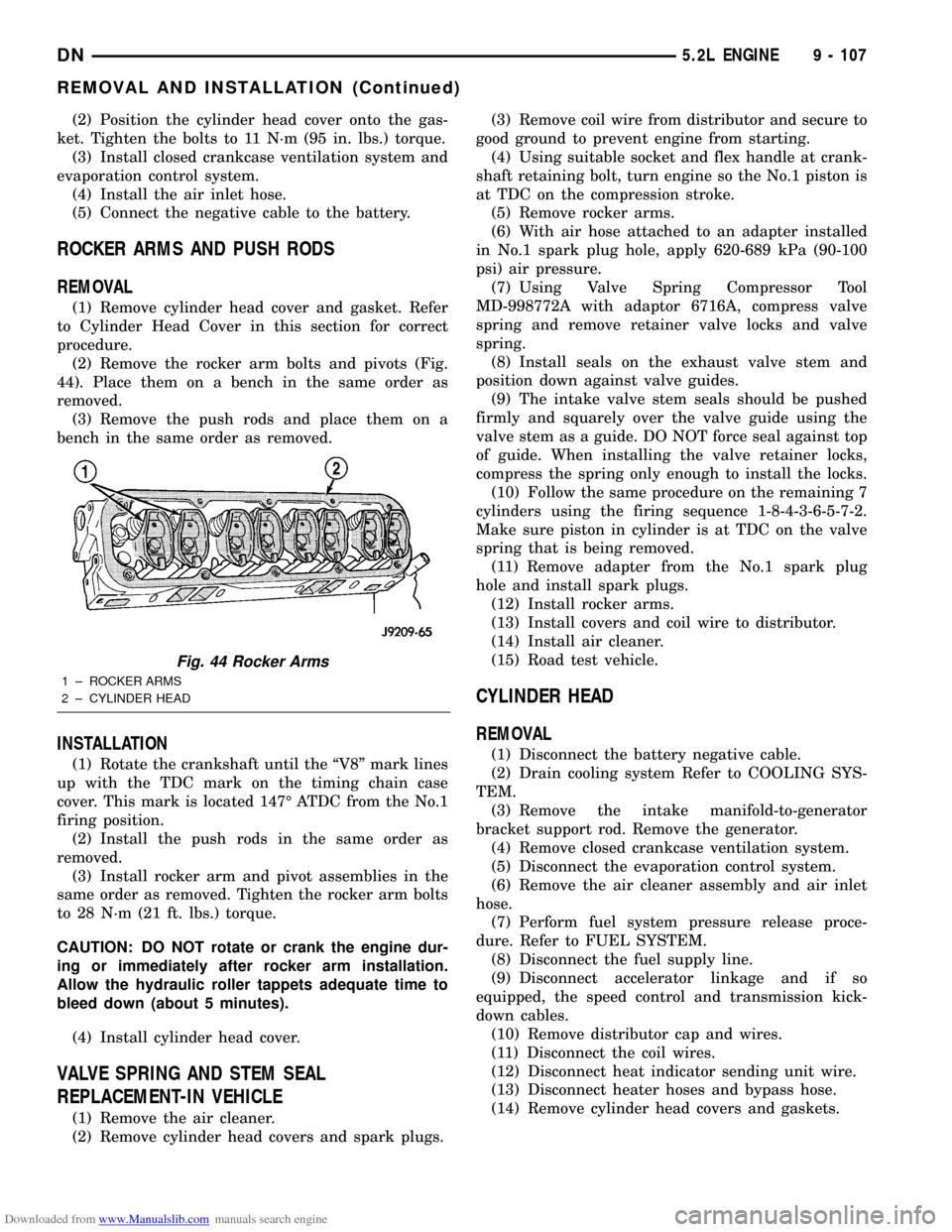
(2) Remove the rocker arm bolts and pivots (Fig.
44). Place them on a bench in the same order as
removed.
(3) Remove the push rods and place them on a
bench in the same order as removed.
INSTALLATION
(1) Rotate the crankshaft until the ªV8º mark lines
up with the TDC mark on the timing chain case
cover. This mark is located 147É ATDC from the No.1
firing position.
(2) Install the push rods in the same order as
removed.
(3) Install rocker arm and pivot assemblies in the
same order as removed. Tighten the rocker arm bolts
to 28 N´m (21 ft. lbs.) torque.
CAUTION: DO NOT rotate or crank the engine dur-
ing or immediately after rocker arm installation.
Allow the hydraulic roller tappets adequate time to
bleed down (about 5 minutes).
(4) Install cylinder head cover.
VALVE SPRING AND STEM SEAL
REPLACEMENT-IN VEHICLE
(1) Remove the air cleaner.
(2) Remove cylinder head covers and spark plugs.(3) Remove coil wire from distributor and secure to
good ground to prevent engine from starting.
(4) Using suitable socket and flex handle at crank-
shaft retaining bolt, turn engine so the No.1 piston is
at TDC on the compression stroke.
(5) Remove rocker arms.
(6) With air hose attached to an adapter installed
in No.1 spark plug hole, apply 620-689 kPa (90-100
psi) air pressure.
(7) Using Valve Spring Compressor Tool
MD-998772A with adaptor 6716A, compress valve
spring and remove retainer valve locks and valve
spring.
(8) Install seals on the exhaust valve stem and
position down against valve guides.
(9) The intake valve stem seals should be pushed
firmly and squarely over the valve guide using the
valve stem as a guide. DO NOT force seal against top
of guide. When installing the valve retainer locks,
compress the spring only enough to install the locks.
(10) Follow the same procedure on the remaining 7
cylinders using the firing sequence 1-8-4-3-6-5-7-2.
Make sure piston in cylinder is at TDC on the valve
spring that is being removed.
(11) Remove adapter from the No.1 spark plug
hole and install spark plugs.
(12) Install rocker arms.
(13) Install covers and coil wire to distributor.
(14) Install air cleaner.
(15) Road test vehicle.
CYLINDER HEAD
REMOVAL
(1) Disconnect the battery negative cable.
(2) Drain cooling system Refer to COOLING SYS-
TEM.
(3) Remove the intake manifold-to-generator
bracket support rod. Remove the generator.
(4) Remove closed crankcase ventilation system.
(5) Disconnect the evaporation control system.
(6) Remove the air cleaner assembly and air inlet
hose.
(7) Perform fuel system pressure release proce-
dure. Refer to FUEL SYSTEM.
(8) Disconnect the fuel supply line.
(9) Disconnect accelerator linkage and if so
equipped, the speed control and transmission kick-
down cables.
(10) Remove distributor cap and wires.
(11) Disconnect the coil wires.
(12) Disconnect heat indicator sending unit wire.
(13) Disconnect heater hoses and bypass hose.
(14) Remove cylinder head covers and gaskets.
Fig. 44 Rocker Arms
1 ± ROCKER ARMS
2 ± CYLINDER HEAD
DN5.2L ENGINE 9 - 107
REMOVAL AND INSTALLATION (Continued)
Page 117 of 193
Downloaded from www.Manualslib.com manuals search engine PISTON AND CONNECTING ROD ASSEMBLY
REMOVAL
(1) Remove the engine from the vehicle.
(2) Remove the cylinder head.
(3) Remove the oil pan.
(4) Remove top ridge of cylinder bores with a reli-
able ridge reamer before removing pistons from cyl-
inder block. Be sure to keep tops of pistons covered
during this operation.
(5) Be sure the connecting rod and connecting rod
cap are identified with the cylinder number. Remove
connecting rod cap. Install connecting rod bolt guide
set on connecting rod bolts.
(6) Pistons and connecting rods must be removed
from top of cylinder block. When removing piston and
connecting rod assemblies, rotate crankshaft to cen-
ter the connecting rod in the cylinder bore and at
BDC.Be careful not to nick crankshaft journals.
(7) After removal, install bearing cap on the mat-
ing rod.
INSTALLATION
(1) Be sure that compression ring gaps are stag-
gered so that neither is in-line with oil ring rail gap.
(2) Before installing the ring compressor, make
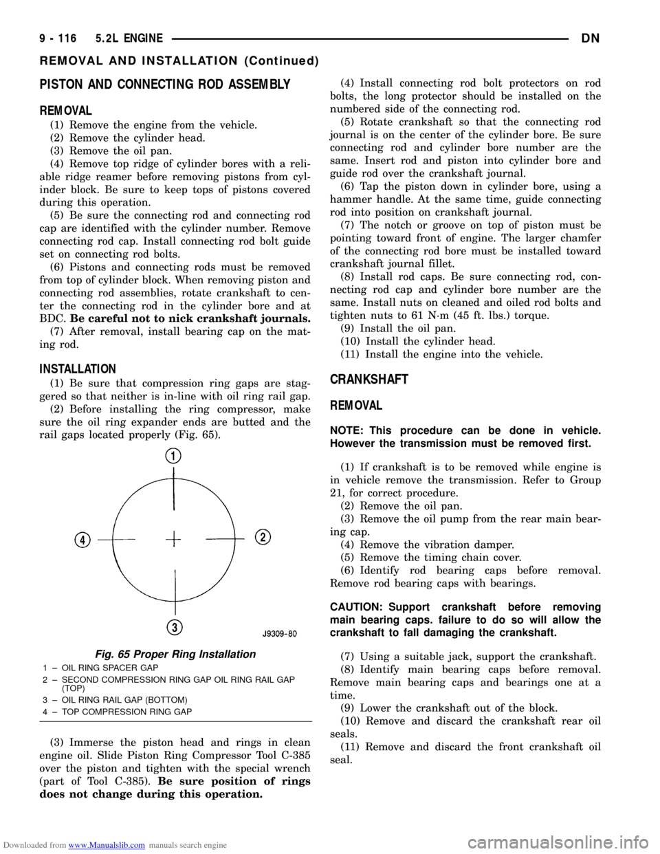
sure the oil ring expander ends are butted and the
rail gaps located properly (Fig. 65).
(3) Immerse the piston head and rings in clean
engine oil. Slide Piston Ring Compressor Tool C-385
over the piston and tighten with the special wrench
(part of Tool C-385).Be sure position of rings
does not change during this operation.(4) Install connecting rod bolt protectors on rod
bolts, the long protector should be installed on the
numbered side of the connecting rod.
(5) Rotate crankshaft so that the connecting rod
journal is on the center of the cylinder bore. Be sure
connecting rod and cylinder bore number are the
same. Insert rod and piston into cylinder bore and
guide rod over the crankshaft journal.
(6) Tap the piston down in cylinder bore, using a
hammer handle. At the same time, guide connecting
rod into position on crankshaft journal.
(7) The notch or groove on top of piston must be
pointing toward front of engine. The larger chamfer
of the connecting rod bore must be installed toward
crankshaft journal fillet.
(8) Install rod caps. Be sure connecting rod, con-
necting rod cap and cylinder bore number are the
same. Install nuts on cleaned and oiled rod bolts and
tighten nuts to 61 N´m (45 ft. lbs.) torque.
(9) Install the oil pan.
(10) Install the cylinder head.
(11) Install the engine into the vehicle.CRANKSHAFT
REMOVAL
NOTE: This procedure can be done in vehicle.
However the transmission must be removed first.
(1) If crankshaft is to be removed while engine is
in vehicle remove the transmission. Refer to Group
21, for correct procedure.
(2) Remove the oil pan.
(3) Remove the oil pump from the rear main bear-
ing cap.
(4) Remove the vibration damper.
(5) Remove the timing chain cover.
(6) Identify rod bearing caps before removal.
Remove rod bearing caps with bearings.
CAUTION: Support crankshaft before removing
main bearing caps. failure to do so will allow the
crankshaft to fall damaging the crankshaft.
(7) Using a suitable jack, support the crankshaft.
(8) Identify main bearing caps before removal.
Remove main bearing caps and bearings one at a
time.
(9) Lower the crankshaft out of the block.
(10) Remove and discard the crankshaft rear oil
seals.
(11) Remove and discard the front crankshaft oil
seal.
Fig. 65 Proper Ring Installation
1 ± OIL RING SPACER GAP
2 ± SECOND COMPRESSION RING GAP OIL RING RAIL GAP
(TOP)
3 ± OIL RING RAIL GAP (BOTTOM)
4 ± TOP COMPRESSION RING GAP
9 - 116 5.2L ENGINEDN
REMOVAL AND INSTALLATION (Continued)
Page 129 of 193
Downloaded from www.Manualslib.com manuals search engine SPECIFICATIONS
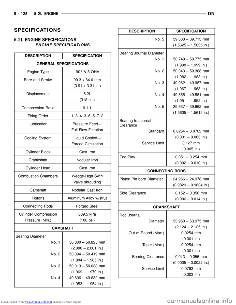
5.2L ENGINE SPECIFICATIONS
ENGINE SPECIFICATIONS
DESCRIPTION SPECIFICATION
GENERAL SPECIFICATIONS
Engine Type 90É V-8 OHV
Bore and Stroke 99.3 x 84.0 mm
(3.91 x 3.31 in.)
Displacement 5.2L
(318 c.i.)
Compression Ratio 9.1:1
Firing Order 1±8±4±3±6±5±7±2
Lubrication Pressure FeedÐ
Full Flow Filtration
Cooling System Liquid CooledÐ
Forced Circulation
Cylinder Block Cast Iron
Crankshaft Nodular Iron
Cylinder Head Cast Iron
Combustion Chambers Wedge-High Swirl
Valve shrouding
Camshaft Nodular Cast Iron
Pistons Aluminum Alloy w/strut
Connecting Rods Forged Steel
Cylinder Compression 689.5 kPa
Pressure (Min.) (100 psi)
CAMSHAFT
Bearing Diameter
No. 1 50.800 ± 50.825 mm
(2.000 ± 2.001 in.)
No. 2 50.394 ± 50.419 mm
(1.984 ± 1.985 in.)
No. 3 50.013 ± 50.038 mm
(1.969 ± 1.970 in.)
No. 4 49.606 ± 49.632 mm
(1.953 ± 1.954 in.)
DESCRIPTION SPECIFICATION
No. 5 39.688 ± 39.713 mm
(1.5625 ± 1.5635 in.)
Bearing Journal Diameter
No. 1 50.749 ± 50.775 mm
(1.998 ± 1.999 in.)
No. 2 50.343 ± 50.368 mm
(1.982 ± 1.983 in.)
No. 3 49.962 ± 49.987 mm
(1.967 ± 1.968 in.)
No. 4 49.555 ± 49.581 mm
(1.951 ± 1.952 in.)
No. 5 39.637 ± 39.662 mm
(1.5605 ± 1.5615 in.)
Bearing to Journal
Clearance
Standard 0.0254 ± 0.0762 mm
(0.001 ± 0.003 in.)
Service Limit 0.127 mm
(0.005 in.)
End Play 0.051 ± 0.254 mm
(0.002 ± 0.010 in.)
CONNECTING RODS
Piston Pin bore Diameter 24.966 ± 24.978 mm
(0.9829 ± 0.9834 in.)
Side Clearance 0.152 ± 0.356 mm
(0.006 ± 0.014 in.)
CRANKSHAFT
Rod Journal
Diameter 53.950 ± 53.975 mm
(2.124 ± 2.125 in.)
Out of Round (Max.) 0.0254 mm
(0.001 in.)
Taper (Max.) 0.0254 mm
(0.001 in.)
Bearing Clearance 0.013 ± 0.056 mm
(0.0005 ± 0.0022 in.)
Service Limit 0.0762 mm
(0.003 in.)
9 - 128 5.2L ENGINEDN