change time DODGE DURANGO 1998 1.G Workshop Manual
[x] Cancel search | Manufacturer: DODGE, Model Year: 1998, Model line: DURANGO, Model: DODGE DURANGO 1998 1.GPages: 193, PDF Size: 5.65 MB
Page 17 of 193
Downloaded from www.Manualslib.com manuals search engine CRANKCASE OIL LEVEL INSPECTION
CAUTION: Do not overfill crankcase with engine oil,
pressure loss or oil foaming can result.
Inspect engine oil level approximately every 800
kilometers (500 miles). Unless the engine has exhib-
ited loss of oil pressure, run the engine for about five
minutes before checking oil level. Checking engine oil
level on a cold engine is not accurate.
To ensure proper lubrication of an engine, the
engine oil must be maintained at an acceptable level.
The acceptable levels are indicated between the ADD
and SAFE marks on the engine oil dipstick.
(1) Position vehicle on level surface.
(2) With engine OFF, allow approximately ten min-
utes for oil to settle to bottom of crankcase, remove
engine oil dipstick.
(3) Wipe dipstick clean.
(4) Install dipstick and verify it is seated in the
tube.
(5) Remove dipstick, with handle held above the
tip, take oil level reading.
(6) Add oil only if level is below the ADD mark on
dipstick.
ENGINE OIL CHANGE
Change engine oil at mileage and time intervals
described in Maintenance Schedules.
Run engine until achieving normal operating tem-
perature.
(1) Position the vehicle on a level surface and turn
engine off.
(2) Hoist and support vehicle on safety stands.
(3) Remove oil fill cap.
(4) Place a suitable drain pan under crankcase
drain.
(5) Remove drain plug from crankcase and allow
oil to drain into pan. Inspect drain plug threads for
stretching or other damage. Replace drain plug if
damaged.
(6) Install drain plug in crankcase.
(7) Lower vehicle and fill crankcase with specified
type and amount of engine oil described in this sec-
tion.
(8) Install oil fill cap.
(9) Start engine and inspect for leaks.
(10) Stop engine and inspect oil level.
ENGINE OIL FILTER CHANGE
FILTER SPECIFICATION
All engines are equipped with a high quality full-
flow, disposable type oil filter. DaimlerChrysler Cor-
poration recommends a Mopar or equivalent oil filter
be used.OIL FILTER REMOVAL
(1) Position a drain pan under the oil filter.
(2) Using a suitable oil filter wrench loosen filter.
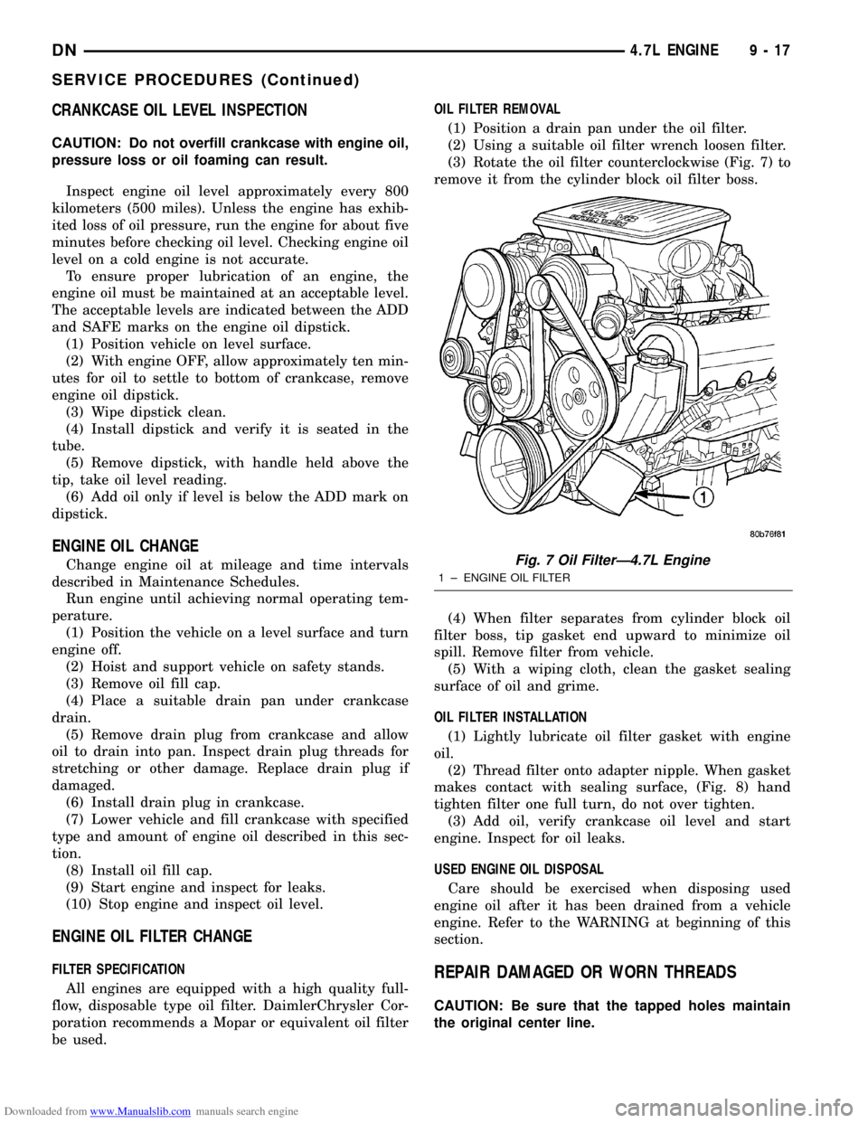
(3) Rotate the oil filter counterclockwise (Fig. 7) to
remove it from the cylinder block oil filter boss.
(4) When filter separates from cylinder block oil
filter boss, tip gasket end upward to minimize oil
spill. Remove filter from vehicle.
(5) With a wiping cloth, clean the gasket sealing
surface of oil and grime.
OIL FILTER INSTALLATION
(1) Lightly lubricate oil filter gasket with engine
oil.
(2) Thread filter onto adapter nipple. When gasket
makes contact with sealing surface, (Fig. 8) hand
tighten filter one full turn, do not over tighten.
(3) Add oil, verify crankcase oil level and start
engine. Inspect for oil leaks.
USED ENGINE OIL DISPOSAL
Care should be exercised when disposing used
engine oil after it has been drained from a vehicle
engine. Refer to the WARNING at beginning of this
section.REPAIR DAMAGED OR WORN THREADS
CAUTION: Be sure that the tapped holes maintain
the original center line.
Fig. 7 Oil FilterÐ4.7L Engine
1 ± ENGINE OIL FILTER
DN4.7L ENGINE 9 - 17
SERVICE PROCEDURES (Continued)
Page 93 of 193
Downloaded from www.Manualslib.com manuals search engine particular ambient temperature range and variation
(Fig. 12).
ENERGY CONSERVING OIL
An Energy Conserving type oil is recommended for
gasoline engines. The designation of ENERGY CON-
SERVING is located on the label of an engine oil con-
tainer.
OIL LEVEL INDICATOR (DIPSTICK)
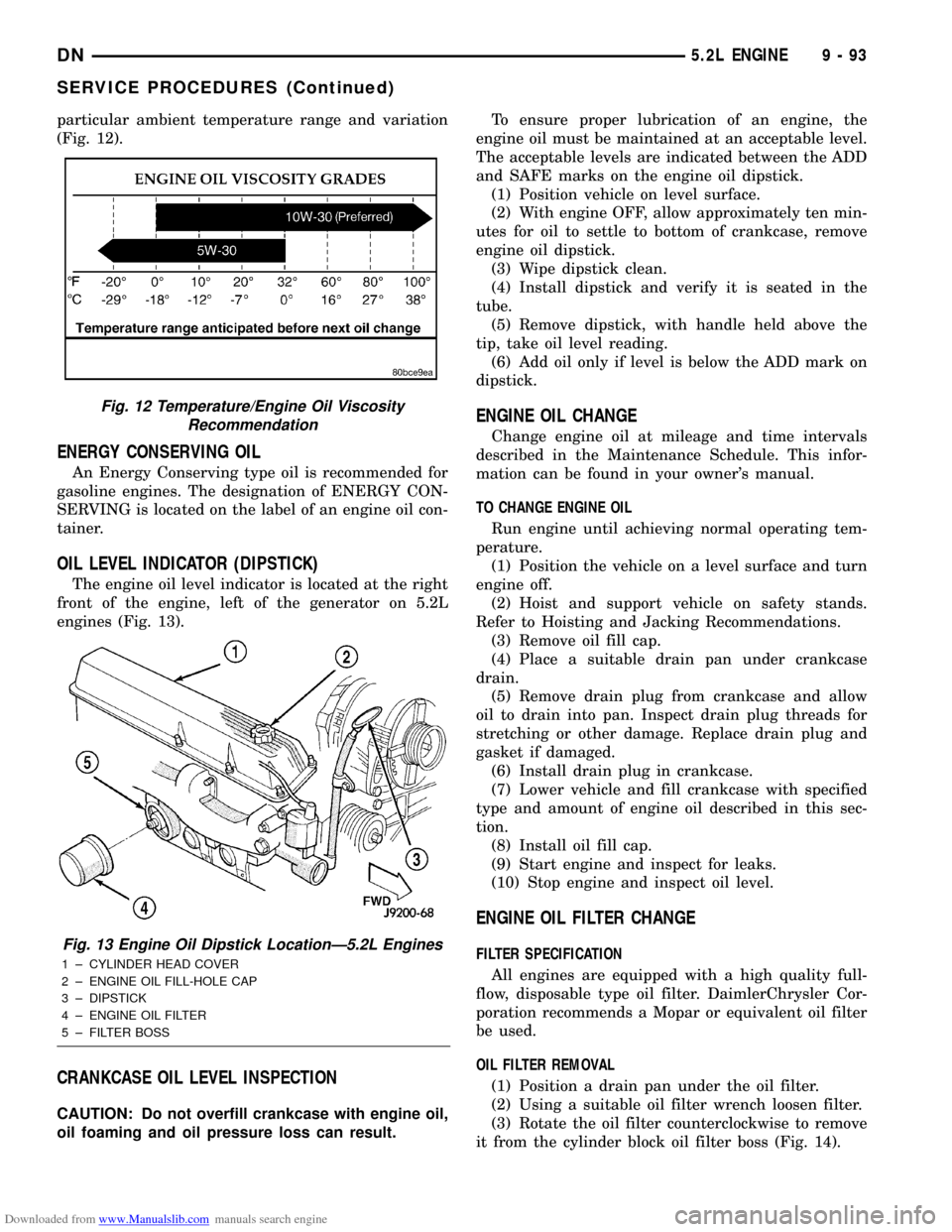
The engine oil level indicator is located at the right
front of the engine, left of the generator on 5.2L
engines (Fig. 13).
CRANKCASE OIL LEVEL INSPECTION
CAUTION: Do not overfill crankcase with engine oil,
oil foaming and oil pressure loss can result.To ensure proper lubrication of an engine, the
engine oil must be maintained at an acceptable level.
The acceptable levels are indicated between the ADD
and SAFE marks on the engine oil dipstick.
(1) Position vehicle on level surface.
(2) With engine OFF, allow approximately ten min-
utes for oil to settle to bottom of crankcase, remove
engine oil dipstick.
(3) Wipe dipstick clean.
(4) Install dipstick and verify it is seated in the
tube.
(5) Remove dipstick, with handle held above the
tip, take oil level reading.
(6) Add oil only if level is below the ADD mark on
dipstick.
ENGINE OIL CHANGE
Change engine oil at mileage and time intervals
described in the Maintenance Schedule. This infor-
mation can be found in your owner's manual.
TO CHANGE ENGINE OIL
Run engine until achieving normal operating tem-
perature.
(1) Position the vehicle on a level surface and turn
engine off.
(2) Hoist and support vehicle on safety stands.
Refer to Hoisting and Jacking Recommendations.
(3) Remove oil fill cap.
(4) Place a suitable drain pan under crankcase
drain.
(5) Remove drain plug from crankcase and allow
oil to drain into pan. Inspect drain plug threads for
stretching or other damage. Replace drain plug and
gasket if damaged.
(6) Install drain plug in crankcase.
(7) Lower vehicle and fill crankcase with specified
type and amount of engine oil described in this sec-
tion.
(8) Install oil fill cap.
(9) Start engine and inspect for leaks.
(10) Stop engine and inspect oil level.
ENGINE OIL FILTER CHANGE
FILTER SPECIFICATION
All engines are equipped with a high quality full-
flow, disposable type oil filter. DaimlerChrysler Cor-
poration recommends a Mopar or equivalent oil filter
be used.
OIL FILTER REMOVAL
(1) Position a drain pan under the oil filter.
(2) Using a suitable oil filter wrench loosen filter.
(3) Rotate the oil filter counterclockwise to remove
it from the cylinder block oil filter boss (Fig. 14).
Fig. 12 Temperature/Engine Oil Viscosity
Recommendation
Fig. 13 Engine Oil Dipstick LocationÐ5.2L Engines
1 ± CYLINDER HEAD COVER
2 ± ENGINE OIL FILL-HOLE CAP
3 ± DIPSTICK
4 ± ENGINE OIL FILTER
5 ± FILTER BOSS
DN5.2L ENGINE 9 - 93
SERVICE PROCEDURES (Continued)
Page 117 of 193
Downloaded from www.Manualslib.com manuals search engine PISTON AND CONNECTING ROD ASSEMBLY
REMOVAL
(1) Remove the engine from the vehicle.
(2) Remove the cylinder head.
(3) Remove the oil pan.
(4) Remove top ridge of cylinder bores with a reli-
able ridge reamer before removing pistons from cyl-
inder block. Be sure to keep tops of pistons covered
during this operation.
(5) Be sure the connecting rod and connecting rod
cap are identified with the cylinder number. Remove
connecting rod cap. Install connecting rod bolt guide
set on connecting rod bolts.
(6) Pistons and connecting rods must be removed
from top of cylinder block. When removing piston and
connecting rod assemblies, rotate crankshaft to cen-
ter the connecting rod in the cylinder bore and at
BDC.Be careful not to nick crankshaft journals.
(7) After removal, install bearing cap on the mat-
ing rod.
INSTALLATION
(1) Be sure that compression ring gaps are stag-
gered so that neither is in-line with oil ring rail gap.
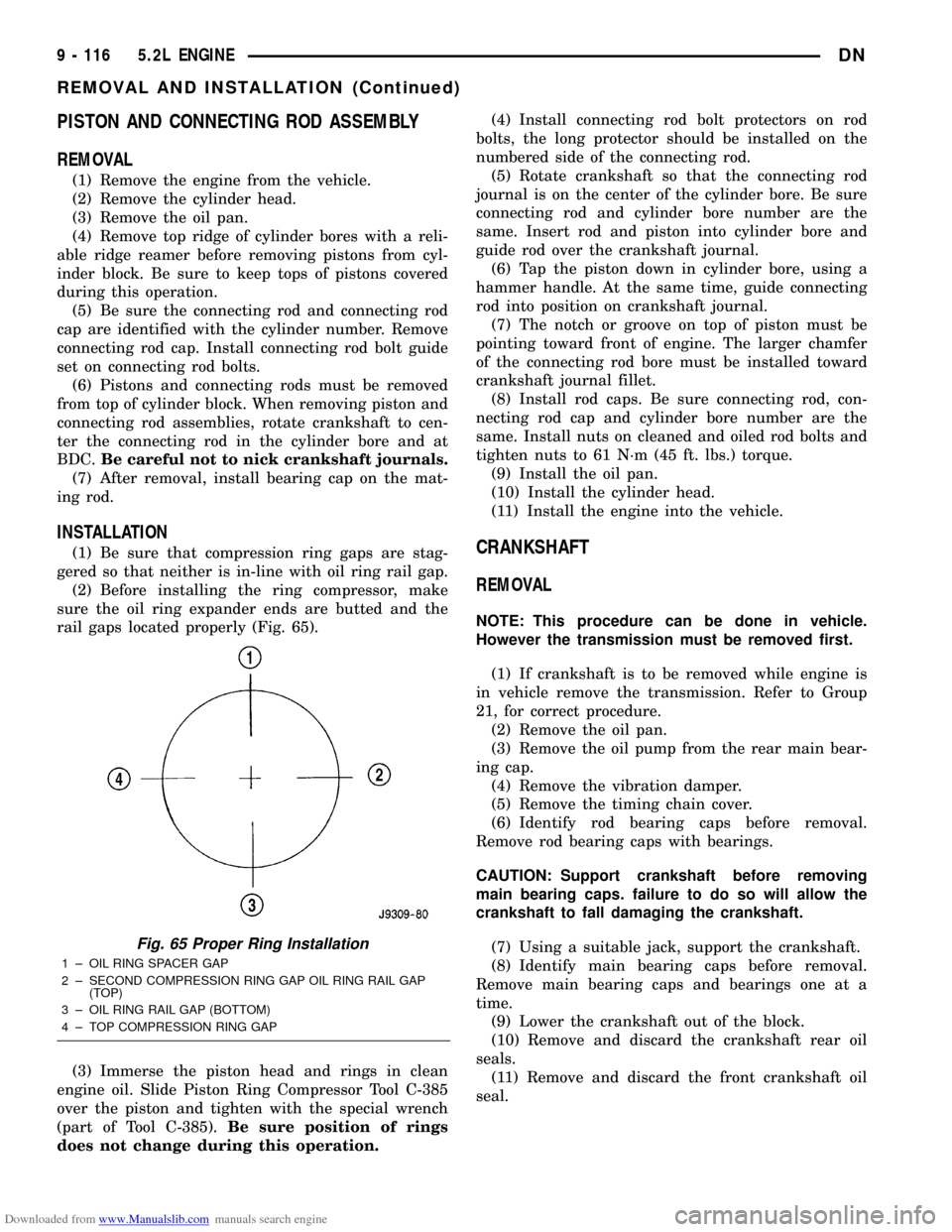
(2) Before installing the ring compressor, make
sure the oil ring expander ends are butted and the
rail gaps located properly (Fig. 65).
(3) Immerse the piston head and rings in clean
engine oil. Slide Piston Ring Compressor Tool C-385
over the piston and tighten with the special wrench
(part of Tool C-385).Be sure position of rings
does not change during this operation.(4) Install connecting rod bolt protectors on rod
bolts, the long protector should be installed on the
numbered side of the connecting rod.
(5) Rotate crankshaft so that the connecting rod
journal is on the center of the cylinder bore. Be sure
connecting rod and cylinder bore number are the
same. Insert rod and piston into cylinder bore and
guide rod over the crankshaft journal.
(6) Tap the piston down in cylinder bore, using a
hammer handle. At the same time, guide connecting
rod into position on crankshaft journal.
(7) The notch or groove on top of piston must be
pointing toward front of engine. The larger chamfer
of the connecting rod bore must be installed toward
crankshaft journal fillet.
(8) Install rod caps. Be sure connecting rod, con-
necting rod cap and cylinder bore number are the
same. Install nuts on cleaned and oiled rod bolts and
tighten nuts to 61 N´m (45 ft. lbs.) torque.
(9) Install the oil pan.
(10) Install the cylinder head.
(11) Install the engine into the vehicle.CRANKSHAFT
REMOVAL
NOTE: This procedure can be done in vehicle.
However the transmission must be removed first.
(1) If crankshaft is to be removed while engine is
in vehicle remove the transmission. Refer to Group
21, for correct procedure.
(2) Remove the oil pan.
(3) Remove the oil pump from the rear main bear-
ing cap.
(4) Remove the vibration damper.
(5) Remove the timing chain cover.
(6) Identify rod bearing caps before removal.
Remove rod bearing caps with bearings.
CAUTION: Support crankshaft before removing
main bearing caps. failure to do so will allow the
crankshaft to fall damaging the crankshaft.
(7) Using a suitable jack, support the crankshaft.
(8) Identify main bearing caps before removal.
Remove main bearing caps and bearings one at a
time.
(9) Lower the crankshaft out of the block.
(10) Remove and discard the crankshaft rear oil
seals.
(11) Remove and discard the front crankshaft oil
seal.
Fig. 65 Proper Ring Installation
1 ± OIL RING SPACER GAP
2 ± SECOND COMPRESSION RING GAP OIL RING RAIL GAP
(TOP)
3 ± OIL RING RAIL GAP (BOTTOM)
4 ± TOP COMPRESSION RING GAP
9 - 116 5.2L ENGINEDN
REMOVAL AND INSTALLATION (Continued)
Page 152 of 193
Downloaded from www.Manualslib.com manuals search engine (2) With engine OFF, allow approximately ten min-
utes for oil to settle to bottom of crankcase, remove
engine oil dipstick.
(3) Wipe dipstick clean.
(4) Install dipstick and verify it is seated in the
tube.
(5) Remove dipstick, with handle held above the
tip, take oil level reading.
(6) Add oil only if level is below the ADD mark on
dipstick.
ENGINE OIL CHANGE
Change engine oil at mileage and time intervals
described in the Maintenance Schedule. This infor-
mation can be found in your owner's manual.
TO CHANGE ENGINE OIL
Run engine until achieving normal operating tem-
perature.
(1) Position the vehicle on a level surface and turn
engine off.
(2) Hoist and support vehicle on safety stands.
Refer to Hoisting and Jacking Recommendations.
(3) Remove oil fill cap.
(4) Place a suitable drain pan under crankcase
drain.
(5) Remove drain plug from crankcase and allow
oil to drain into pan. Inspect drain plug threads for
stretching or other damage. Replace drain plug and
gasket if damaged.
(6) Install drain plug in crankcase.(7) Lower vehicle and fill crankcase with specified
type and amount of engine oil described in this sec-
tion.
(8) Install oil fill cap.
(9) Start engine and inspect for leaks.
(10) Stop engine and inspect oil level.
ENGINE OIL FILTER CHANGE
FILTER SPECIFICATION
All engines are equipped with a high quality full-
flow, disposable type oil filter. DaimlerChrysler Cor-
poration recommends a Mopar or equivalent oil filter
be used.
OIL FILTER REMOVAL
(1) Position a drain pan under the oil filter.
(2) Using a suitable oil filter wrench loosen filter.
(3) Rotate the oil filter counterclockwise to remove
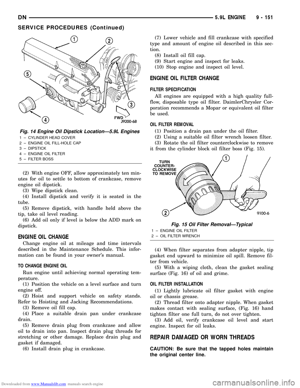
it from the cylinder block oil filter boss (Fig. 15).
(4) When filter separates from adapter nipple, tip
gasket end upward to minimize oil spill. Remove fil-
ter from vehicle.
(5) With a wiping cloth, clean the gasket sealing
surface (Fig. 16) of oil and grime.
OIL FILTER INSTALLATION
(1) Lightly lubricate oil filter gasket with engine
oil or chassis grease.
(2) Thread filter onto adapter nipple. When gasket
makes contact with sealing surface, (Fig. 16) hand
tighten filter one full turn, do not over tighten.
(3) Add oil, verify crankcase oil level and start
engine. Inspect for oil leaks.
REPAIR DAMAGED OR WORN THREADS
CAUTION: Be sure that the tapped holes maintain
the original center line.
Fig. 14 Engine Oil Dipstick LocationÐ5.9L Engines
1 ± CYLINDER HEAD COVER
2 ± ENGINE OIL FILL-HOLE CAP
3 ± DIPSTICK
4 ± ENGINE OIL FILTER
5 ± FILTER BOSS
Fig. 15 Oil Filter RemovalÐTypical
1 ± ENGINE OIL FILTER
2 ± OIL FILTER WRENCH
DN5.9L ENGINE 9 - 151
SERVICE PROCEDURES (Continued)
Page 177 of 193
Downloaded from www.Manualslib.com manuals search engine INSTALLATION
(1) Be sure that compression ring gaps are stag-
gered so that neither is in-line with oil ring rail gap.
(2) Before installing the ring compressor, make
sure the oil ring expander ends are butted and the
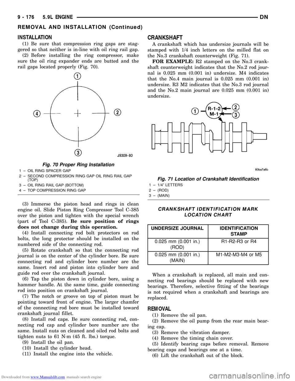
rail gaps located properly (Fig. 70).
(3) Immerse the piston head and rings in clean
engine oil. Slide Piston Ring Compressor Tool C-385
over the piston and tighten with the special wrench
(part of Tool C-385).Be sure position of rings
does not change during this operation.
(4) Install connecting rod bolt protectors on rod
bolts, the long protector should be installed on the
numbered side of the connecting rod.
(5) Rotate crankshaft so that the connecting rod
journal is on the center of the cylinder bore. Be sure
connecting rod and cylinder bore number are the
same. Insert rod and piston into cylinder bore and
guide rod over the crankshaft journal.
(6) Tap the piston down in cylinder bore, using a
hammer handle. At the same time, guide connecting
rod into position on crankshaft journal.
(7) The notch or groove on top of piston must be
pointing toward front of engine. The larger chamfer
of the connecting rod bore must be installed toward
crankshaft journal fillet.
(8) Install rod caps. Be sure connecting rod, con-
necting rod cap and cylinder bore number are the
same. Install nuts on cleaned and oiled rod bolts and
tighten nuts to 61 N´m (45 ft. lbs.) torque.
(9) Install the oil pan.
(10) Install the cylinder head.
(11) Install the engine into the vehicle.
CRANKSHAFT
A crankshaft which has undersize journals will be
stamped with 1/4 inch letters on the milled flat on
the No.3 crankshaft counterweight (Fig. 71).
FOR EXAMPLE:R2 stamped on the No.3 crank-
shaft counterweight indicates that the No.2 rod jour-
nal is 0.025 mm (0.001 in) undersize. M4 indicates
that the No.4 main journal is 0.025 mm (0.001 in)
undersize. R3 M2 indicates that the No.3 rod journal
and the No.2 main journal are 0.025 mm (0.001 in)
undersize.
When a crankshaft is replaced, all main and con-
necting rod bearings should be replaced with new
bearings. Therefore, selective fitting of the bearings
is not required when a crankshaft and bearings are
replaced.
REMOVAL
(1) Remove the oil pan.
(2) Remove the oil pump from the rear main bear-
ing cap.
(3) Remove the vibration damper.
(4) Remove the timing chain cover.
(5) Identify bearing caps before removal. Remove
bearing caps and bearings one at a time.
(6) Lift the crankshaft out of the block.
Fig. 70 Proper Ring Installation
1 ± OIL RING SPACER GAP
2 ± SECOND COMPRESSION RING GAP OIL RING RAIL GAP
(TOP)
3 ± OIL RING RAIL GAP (BOTTOM)
4 ± TOP COMPRESSION RING GAP
Fig. 71 Location of Crankshaft Identification
1 ± 1/4º LETTERS
2 ± (ROD)
3 ± (MAIN)
CRANKSHAFT IDENTIFICATION MARK
LOCATION CHART
UNDERSIZE JOURNAL IDENTIFICATION
STAMP
0.025 mm (0.001 in.)
(ROD)R1-R2-R3 or R4
0.025 mm (0.001 in.)
(MAIN)M1-M2-M3-M4 or M5
9 - 176 5.9L ENGINEDN
REMOVAL AND INSTALLATION (Continued)