Eco DODGE DURANGO 1999 1.G User Guide
[x] Cancel search | Manufacturer: DODGE, Model Year: 1999, Model line: DURANGO, Model: DODGE DURANGO 1999 1.GPages: 193, PDF Size: 5.65 MB
Page 20 of 193
Downloaded from www.Manualslib.com manuals search engine (3) Note the location of the V8 mark stamped into
the camshaft drive gears (Fig. 12). If the V8 mark on
each camshaft drive gear is at the twelve o'clock posi-
tion, the engine is at TDC on the exhaust stroke. If
the V8 mark on each gear is at the six o'clock posi-
tion, the engine is at TDC on the compression stroke.
(4) If both of the camshaft drive gears are off in
the same or opposite directions, the primary chain or
both secondary chains are at fault. Refer to Timing
Chain and Sprockets procedure in this section.
(5) If only one of the camshaft drive gears is off
and the other is correct, the problem is confined to
one secondary chain. Refer to Single camshaft tim-
ing, in this procedure.
(6) If both camshaft drive gear V8 marks are at
the twelve o'clock or the six o' clock position the
engine base timing is correct. Reinstall the cylinder
head covers.
SINGLE CAMSHAFT TIMING
NOTE: to adjust the timing on one camshaft, pre-
form the following procedure.
(1) Using Chain Tensioner Wedge, special tool
8350, stabilize the secondary chain drive. For refer-
ence purposes, mark the chain-to-sprocket position
(Fig. 13).
(2) Remove the camshaft drive gear retaining bolt.
(3) Carefully remove the camshaft drive gear from
the camshaft.
(4) Re-index the camshaft drive gear in the chain
until the V8 mark is at the same position as the V8
mark on the opposite camshaft drive gear.
NOTE: When gripping the camshaft, place the pli-
ers on the tube portion of the camshaft only. Do not
grip the lobes or the sprocket areas.
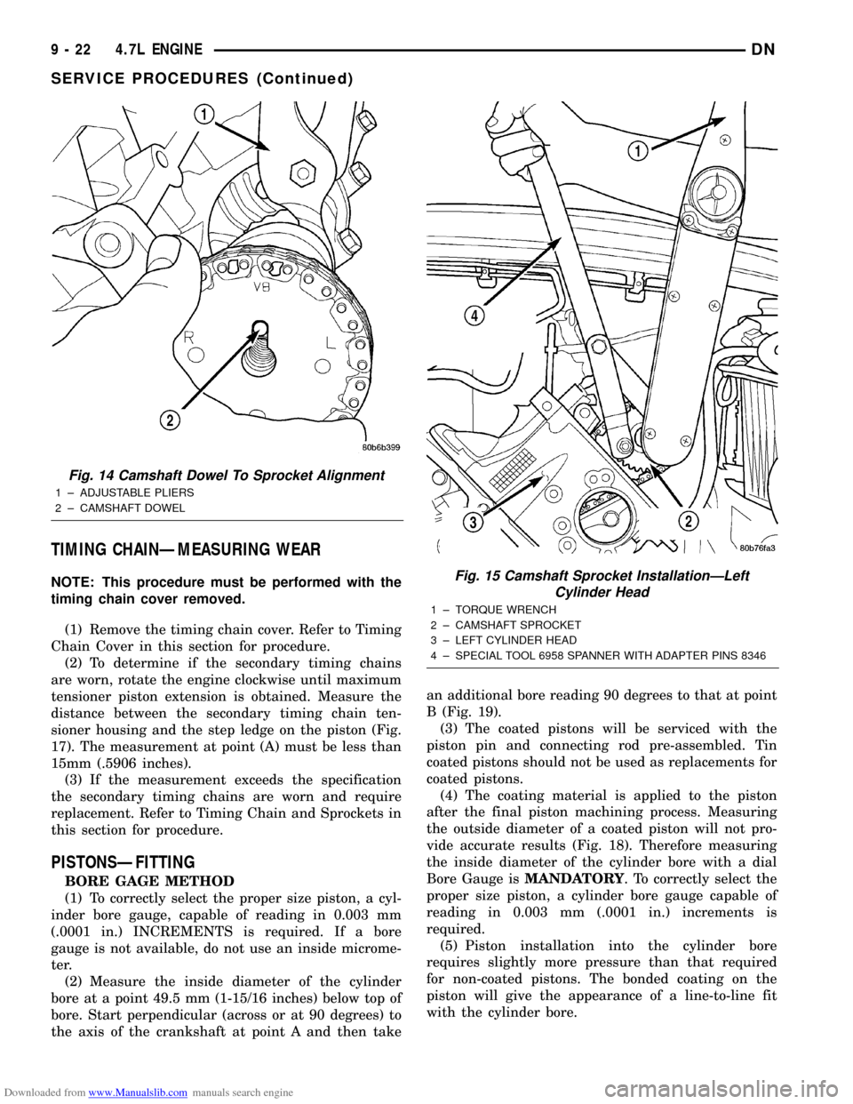
(5) Using a suitable pair of adjustable pliers,
rotate the camshaft until the alignment dowel on the
camshaft is aligned with the slot in the camshaft
drive gear (Fig. 14).
CAUTION: Remove excess oil from camshaft
sprocket retaining bolt before reinstalling bolt. Fail-
ure to do so may cause over-torqueing of bolt
resulting in bolt failure.
(6) Position the camshaft drive gear onto the cam-
shaft, remove oil from bolt then install the retaining
bolt. Using Special Tools, Spanner Wrench 6958 with
Adapter Pins 8346 and a suitable torque wrench,
Tighten retaining bolt to 122N´m (90 ft. Lbs.) (Fig.
15) (Fig. 16).
(7) Remove special tool 8350.
(8) Rotate the crankshaft two full revolutions, then
reverify that the camshaft drive gear V8 marks are
in fact aligned.
(9) Install the cylinder head covers. Refer to Cylin-
der Head Cover in this section.
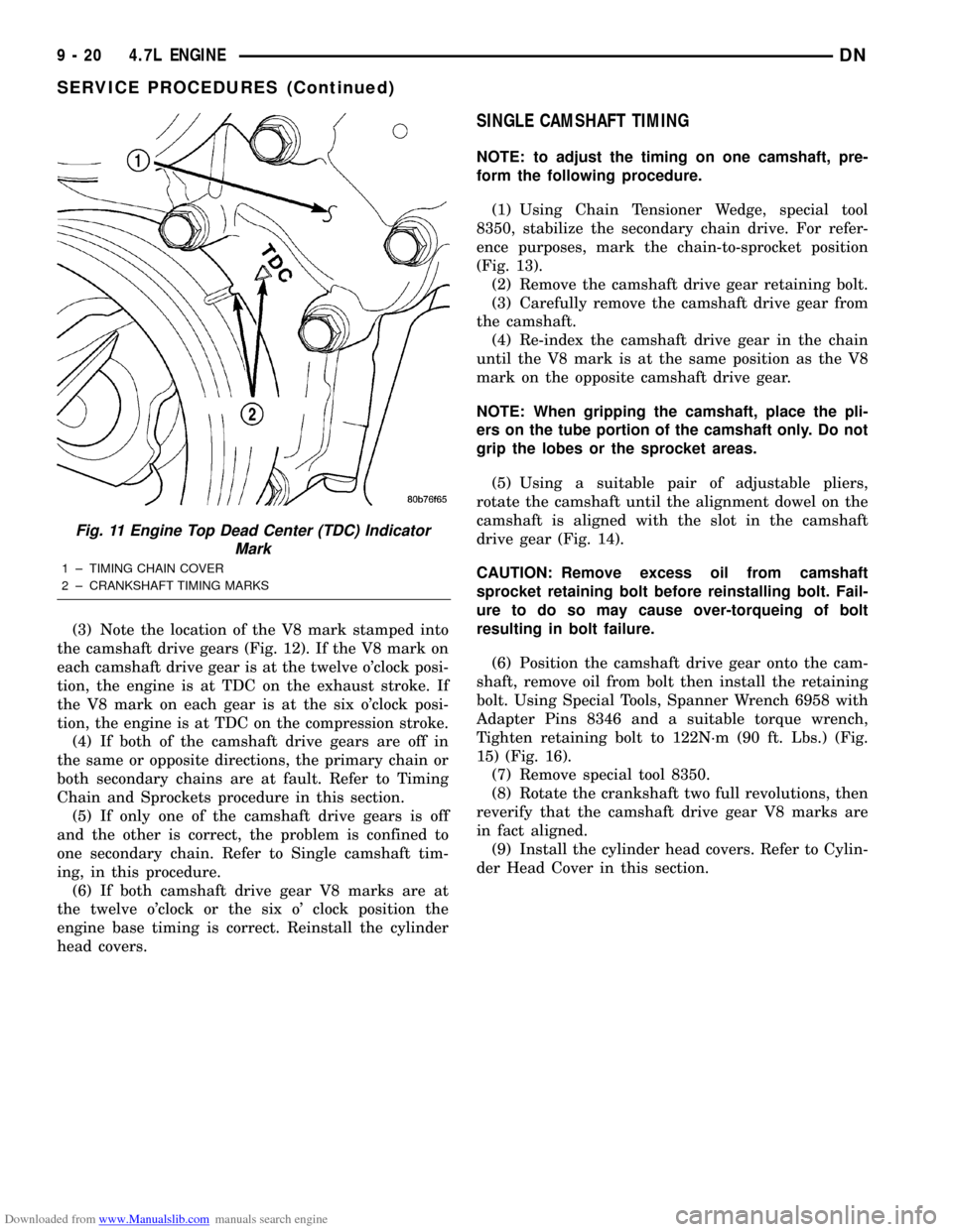
Fig. 11 Engine Top Dead Center (TDC) Indicator
Mark
1 ± TIMING CHAIN COVER
2 ± CRANKSHAFT TIMING MARKS
9 - 20 4.7L ENGINEDN
SERVICE PROCEDURES (Continued)
Page 22 of 193
Downloaded from www.Manualslib.com manuals search engine TIMING CHAINÐMEASURING WEAR
NOTE: This procedure must be performed with the
timing chain cover removed.
(1) Remove the timing chain cover. Refer to Timing
Chain Cover in this section for procedure.
(2) To determine if the secondary timing chains
are worn, rotate the engine clockwise until maximum
tensioner piston extension is obtained. Measure the
distance between the secondary timing chain ten-
sioner housing and the step ledge on the piston (Fig.
17). The measurement at point (A) must be less than
15mm (.5906 inches).
(3) If the measurement exceeds the specification
the secondary timing chains are worn and require
replacement. Refer to Timing Chain and Sprockets in
this section for procedure.
PISTONSÐFITTING
BORE GAGE METHOD
(1) To correctly select the proper size piston, a cyl-
inder bore gauge, capable of reading in 0.003 mm
(.0001 in.) INCREMENTS is required. If a bore
gauge is not available, do not use an inside microme-
ter.
(2) Measure the inside diameter of the cylinder
bore at a point 49.5 mm (1-15/16 inches) below top of
bore. Start perpendicular (across or at 90 degrees) to
the axis of the crankshaft at point A and then takean additional bore reading 90 degrees to that at point
B (Fig. 19).
(3) The coated pistons will be serviced with the
piston pin and connecting rod pre-assembled. Tin
coated pistons should not be used as replacements for
coated pistons.
(4) The coating material is applied to the piston
after the final piston machining process. Measuring
the outside diameter of a coated piston will not pro-
vide accurate results (Fig. 18). Therefore measuring
the inside diameter of the cylinder bore with a dial
Bore Gauge isMANDATORY. To correctly select the
proper size piston, a cylinder bore gauge capable of
reading in 0.003 mm (.0001 in.) increments is
required.
(5) Piston installation into the cylinder bore
requires slightly more pressure than that required
for non-coated pistons. The bonded coating on the
piston will give the appearance of a line-to-line fit
with the cylinder bore.
Fig. 14 Camshaft Dowel To Sprocket Alignment
1 ± ADJUSTABLE PLIERS
2 ± CAMSHAFT DOWEL
Fig. 15 Camshaft Sprocket InstallationÐLeft
Cylinder Head
1 ± TORQUE WRENCH
2 ± CAMSHAFT SPROCKET
3 ± LEFT CYLINDER HEAD
4 ± SPECIAL TOOL 6958 SPANNER WITH ADAPTER PINS 8346
9 - 22 4.7L ENGINEDN
SERVICE PROCEDURES (Continued)
Page 23 of 193
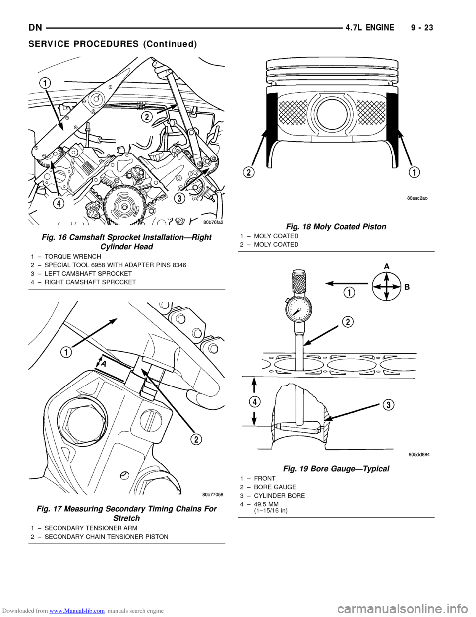
Downloaded from www.Manualslib.com manuals search engine Fig. 16 Camshaft Sprocket InstallationÐRight
Cylinder Head
1 ± TORQUE WRENCH
2 ± SPECIAL TOOL 6958 WITH ADAPTER PINS 8346
3 ± LEFT CAMSHAFT SPROCKET
4 ± RIGHT CAMSHAFT SPROCKET
Fig. 17 Measuring Secondary Timing Chains For
Stretch
1 ± SECONDARY TENSIONER ARM
2 ± SECONDARY CHAIN TENSIONER PISTON
Fig. 18 Moly Coated Piston
1 ± MOLY COATED
2 ± MOLY COATED
Fig. 19 Bore GaugeÐTypical
1 ± FRONT
2 ± BORE GAUGE
3 ± CYLINDER BORE
4 ± 49.5 MM
(1±15/16 in)
DN4.7L ENGINE 9 - 23
SERVICE PROCEDURES (Continued)
Page 41 of 193
Downloaded from www.Manualslib.com manuals search engine (4) For rocker arm installation on cylinders 1 and
7 Rotate the crankshaft until cylinder #2 is at TDC
compression stroke.
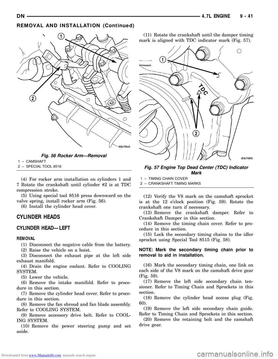
(5) Using special tool 8516 press downward on the
valve spring, install rocker arm (Fig. 56).
(6) Install the cylinder head cover.
CYLINDER HEADS
CYLINDER HEADÐLEFT
REMOVAL
(1) Disconnect the negative cable from the battery.
(2) Raise the vehicle on a hoist.
(3) Disconnect the exhaust pipe at the left side
exhaust manifold.
(4) Drain the engine coolant. Refer to COOLING
SYSTEM.
(5) Lower the vehicle.
(6) Remove the intake manifold. Refer to proce-
dure in this section.
(7) Remove the cylinder head cover. Refer to proce-
dure in this section.
(8) Remove the fan shroud and fan blade assembly.
Refer to COOLING SYSTEM.
(9) Remove accessory drive belt. Refer to COOL-
ING SYSTEM.
(10) Remove the power steering pump and set
aside.(11) Rotate the crankshaft until the damper timing
mark is aligned with TDC indicator mark (Fig. 57).
(12) Verify the V8 mark on the camshaft sprocket
is at the 12 o'clock position (Fig. 59). Rotate the
crankshaft one turn if necessary.
(13) Remove the crankshaft damper. Refer to
Crankshaft Damper in this section.
(14) Remove the timing chain cover. Refer to pro-
cedure in this section.
(15) Lock the secondary timing chains to the idler
sprocket using Special Tool 8515 (Fig. 58).
NOTE: Mark the secondary timing chain prior to
removal to aid in installation.
(16) Mark the secondary timing chain, one link on
each side of the V8 mark on the camshaft drive gear
(Fig. 59).
(17) Remove the left side secondary chain ten-
sioner. Refer to Timing Chain and Sprockets in this
section.
(18) Remove the cylinder head access plug (Fig.
60).
(19) Remove the left side secondary chain guide.
Refer to Timing Chain and Sprockets in this section.
(20) Remove the retaining bolt and the camshaft
drive gear.
Fig. 56 Rocker ArmÐRemoval
1 ± CAMSHAFT
2 ± SPECIAL TOOL 8516
Fig. 57 Engine Top Dead Center (TDC) Indicator
Mark
1 ± TIMING CHAIN COVER
2 ± CRANKSHAFT TIMING MARKS
DN4.7L ENGINE 9 - 41
REMOVAL AND INSTALLATION (Continued)
Page 42 of 193
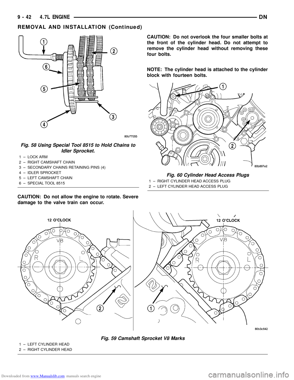
Downloaded from www.Manualslib.com manuals search engine CAUTION: Do not allow the engine to rotate. Severe
damage to the valve train can occur.CAUTION: Do not overlook the four smaller bolts at
the front of the cylinder head. Do not attempt to
remove the cylinder head without removing these
four bolts.
NOTE: The cylinder head is attached to the cylinder
block with fourteen bolts.
Fig. 59 Camshaft Sprocket V8 Marks
1 ± LEFT CYLINDER HEAD
2 ± RIGHT CYLINDER HEAD
Fig. 60 Cylinder Head Access Plugs
1 ± RIGHT CYLINDER HEAD ACCESS PLUG
2 ± LEFT CYLINDER HEAD ACCESS PLUG
Fig. 58 Using Special Tool 8515 to Hold Chains to
Idler Sprocket.
1 ± LOCK ARM
2 ± RIGHT CAMSHAFT CHAIN
3 ± SECONDARY CHAINS RETAINING PINS (4)
4 ± IDLER SPROCKET
5 ± LEFT CAMSHAFT CHAIN
6 ± SPECIAL TOOL 8515
9 - 42 4.7L ENGINEDN
REMOVAL AND INSTALLATION (Continued)
Page 43 of 193
Downloaded from www.Manualslib.com manuals search engine (21) Remove the cylinder head retaining bolts.
(22) Remove the cylinder head and gasket. Discard
the gasket.
CAUTION: Do not lay the cylinder head on its gas-
ket sealing surface, due to the design of the cylin-
der head gasket any distortion to the cylinder head
sealing surface may prevent the gasket from prop-
erly sealing resulting in leaks.
INSTALLATION
NOTE: The cylinder head bolts are tightened using
a torque plus angle procedure. The bolts must be
examined BEFORE reuse. If the threads are necked
down the bolts should be replaced.
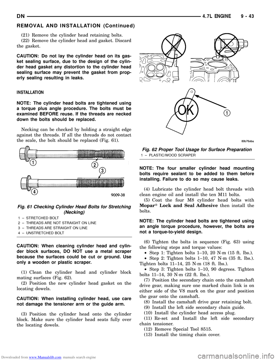
Necking can be checked by holding a straight edge
against the threads. If all the threads do not contact
the scale, the bolt should be replaced (Fig. 61).
CAUTION: When cleaning cylinder head and cylin-
der block surfaces, DO NOT use a metal scraper
because the surfaces could be cut or ground. Use
only a wooden or plastic scraper.
(1) Clean the cylinder head and cylinder block
mating surfaces (Fig. 62).
(2) Position the new cylinder head gasket on the
locating dowels.
CAUTION: When installing cylinder head, use care
not damage the tensioner arm or the guide arm.
(3) Position the cylinder head onto the cylinder
block. Make sure the cylinder head seats fully over
the locating dowels.NOTE: The four smaller cylinder head mounting
bolts require sealant to be added to them before
installing. Failure to do so may cause leaks.
(4) Lubricate the cylinder head bolt threads with
clean engine oil and install the ten M11 bolts.
(5) Coat the four M8 cylinder head bolts with
MopartLock and Seal Adhesivethen install the
bolts.
NOTE: The cylinder head bolts are tightened using
an angle torque procedure, however, the bolts are
not a torque-to-yield design.
(6) Tighten the bolts in sequence (Fig. 63) using
the following steps and torque values:
²Step 1: Tighten bolts 1±10, 20 N´m (15 ft. lbs.).
²Step 2: Tighten bolts 1±10, 47 N´m (35 ft. lbs.).
Tighten bolts 11±14, 25 N´m (18 ft. lbs.).
²Step 3: Tighten bolts 1±10, 90 degrees. Tighten
bolts 11±14, 30 N´m (22 ft. lbs.).
(7) Position the secondary chain onto the camshaft
drive gear, making sure one marked chain link is on
either side of the V8 mark on the gear and position
the gear onto the camshaft.
(8) Install the camshaft drive gear retaining bolt.
(9) Install the left side secondary chain guide.
(10) Install the cylinder head access plug.
(11) Re-set and Install the left side secondary
chain tensioner.
(12) Remove Special Tool 8515.
(13) Install the timing chain cover.
Fig. 61 Checking Cylinder Head Bolts for Stretching
(Necking)
1 ± STRETCHED BOLT
2 ± THREADS ARE NOT STRAIGHT ON LINE
3 ± THREADS ARE STRAIGHT ON LINE
4 ± UNSTRETCHED BOLT
Fig. 62 Proper Tool Usage for Surface Preparation
1 ± PLASTIC/WOOD SCRAPER
DN4.7L ENGINE 9 - 43
REMOVAL AND INSTALLATION (Continued)
Page 44 of 193
Downloaded from www.Manualslib.com manuals search engine (14) Install the crankshaft damper. Tighten
damper bolt 175 N´m (130 Ft. Lbs.).
(15) Install the power steering pump.
(16) Install the fan blade assembly and fan
shroud.
(17) Install the cylinder head cover.
(18) Install the intake manifold.
(19) Refill the cooling system
(20) Raise the vehicle.
(21) Install the exhaust pipe onto the left exhaust
manifold.
(22) Lower the vehicle.
(23) Connect the negative cable to the battery.
(24) Start the engine and check for leaks.
CYLINDER HEADÐRIGHT
REMOVAL
(1) Disconnect battery negitive cable.
(2) Raise the vehicle on a hoist.
(3) Disconnect the exhaust pipe at the right side
exhaust manifold.
(4) Drain the engine coolant. Refer to COOLING
SYSTEM.
(5) Lower the vehicle.
(6) Remove the intake manifold. Refer to proce-
dure in this section.
(7) Remove the cylinder head cover. Refer to proce-
dure in this section.
(8) Remove the fan shroud. Refer to COOLING
SYSTEM.
(9) Remove oil fill housing from cylinder head.
(10) Remove accessory drive belt. Refer to COOL-
ING SYSTEM.
(11) Rotate the crankshaft until the damper timing
mark is aligned with TDC indicator mark (Fig. 57).
(12) Verify the V8 mark on the camshaft sprocket
is at the 12 o'clock position (Fig. 59). Rotate the
crankshaft one turn if necessary.
(13) Remove the crankshaft damper. Refer to
Crankshaft Damper in this section.(14) Remove the timing chain cover. Refer to Tim-
ing Chain Cover in this section.
(15) Lock the secondary timing chains to the idler
sprocket using Special Tool 8515 (Fig. 58).
NOTE: Mark the secondary timing chain prior to
removal to aid in installation.
(16) Mark the secondary timing chain, one link on
each side of the V8 mark on the camshaft drive gear
(Fig. 59).
(17) Remove the right side secondary chain ten-
sioner. Refer to Timing Chain and Sprockets in this
section.
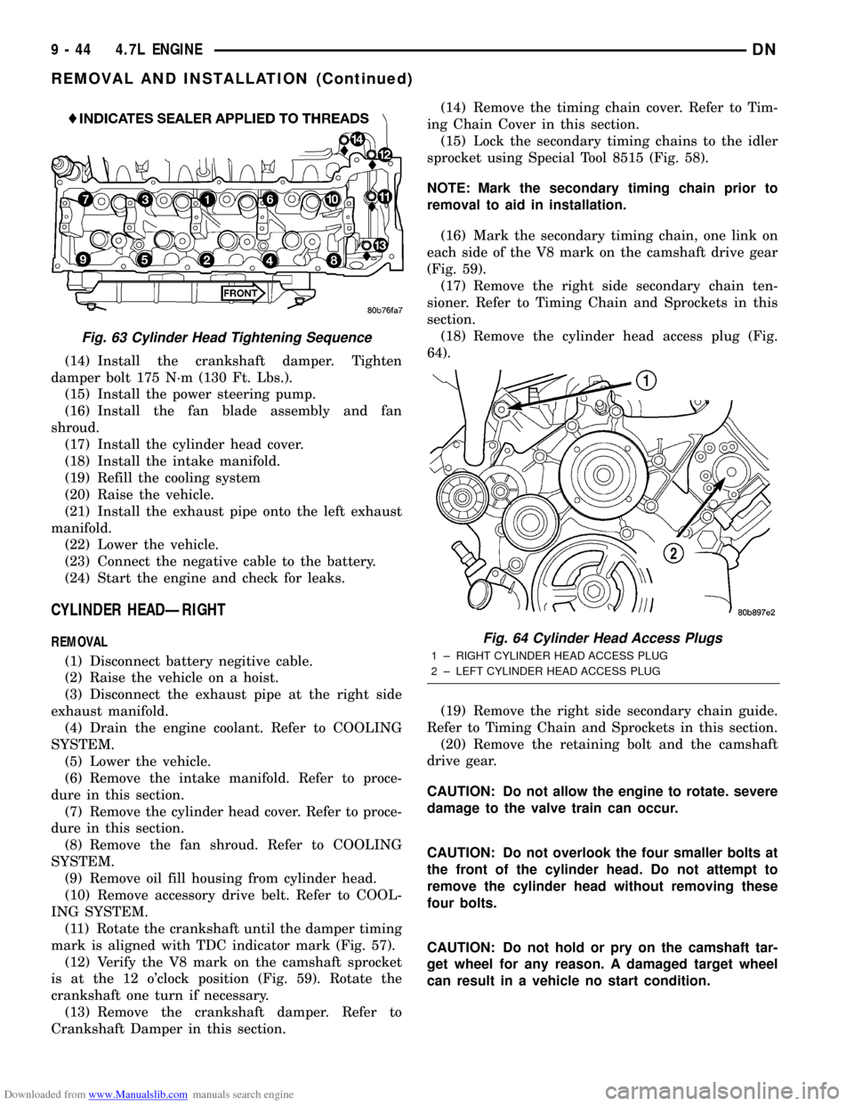
(18) Remove the cylinder head access plug (Fig.
64).
(19) Remove the right side secondary chain guide.
Refer to Timing Chain and Sprockets in this section.
(20) Remove the retaining bolt and the camshaft
drive gear.
CAUTION: Do not allow the engine to rotate. severe
damage to the valve train can occur.
CAUTION: Do not overlook the four smaller bolts at
the front of the cylinder head. Do not attempt to
remove the cylinder head without removing these
four bolts.
CAUTION: Do not hold or pry on the camshaft tar-
get wheel for any reason. A damaged target wheel
can result in a vehicle no start condition.
Fig. 63 Cylinder Head Tightening Sequence
Fig. 64 Cylinder Head Access Plugs
1 ± RIGHT CYLINDER HEAD ACCESS PLUG
2 ± LEFT CYLINDER HEAD ACCESS PLUG
9 - 44 4.7L ENGINEDN
REMOVAL AND INSTALLATION (Continued)
Page 45 of 193
Downloaded from www.Manualslib.com manuals search engine NOTE: The cylinder head is attached to the cylinder
block with fourteen bolts.
(21) Remove the cylinder head retaining bolts.
(22) Remove the cylinder head and gasket. Discard
the gasket.
CAUTION: Do not lay the cylinder head on its gas-
ket sealing surface, do to the design of the cylinder
head gasket any distortion to the cylinder head
sealing surface may prevent the gasket from prop-
erly sealing resulting in leaks.
INSTALLATION
NOTE: The cylinder head bolts are tightened using
a torque plus angle procedure. The bolts must be
examined BEFORE reuse. If the threads are necked
down the bolts should be replaced.
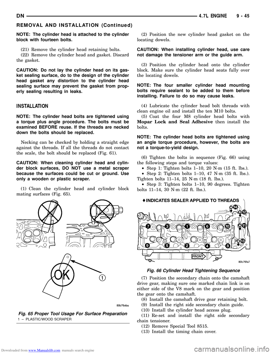
Necking can be checked by holding a straight edge
against the threads. If all the threads do not contact
the scale, the bolt should be replaced (Fig. 61).
CAUTION: When cleaning cylinder head and cylin-
der block surfaces, DO NOT use a metal scraper
because the surfaces could be cut or ground. Use
only a wooden or plastic scraper.
(1) Clean the cylinder head and cylinder block
mating surfaces (Fig. 65).(2) Position the new cylinder head gasket on the
locating dowels.
CAUTION: When installing cylinder head, use care
not damage the tensioner arm or the guide arm.
(3) Position the cylinder head onto the cylinder
block. Make sure the cylinder head seats fully over
the locating dowels.
NOTE: The four smaller cylinder head mounting
bolts require sealant to be added to them before
installing. Failure to do so may cause leaks.
(4) Lubricate the cylinder head bolt threads with
clean engine oil and install the ten M10 bolts.
(5) Coat the four M8 cylinder head bolts with
Mopar Lock and Seal Adhesivethen install the
bolts.
NOTE: The cylinder head bolts are tightened using
an angle torque procedure, however, the bolts are
not a torque-to-yield design.
(6) Tighten the bolts in sequence (Fig. 66) using
the following steps and torque values:
²Step 1: Tighten bolts 1±10, 20 N´m (15 ft. lbs.).
²Step 2: Tighten bolts 1±10, 47 N´m (35 ft. lbs.).
Tighten bolts 11±14, 25 N´m (18 ft. lbs.).
²Step 3: Tighten bolts 1±10, 90 degrees. Tighten
bolts 11±14, 30 N´m (22 ft. lbs.).
(7) Position the secondary chain onto the camshaft
drive gear, making sure one marked chain link is on
either side of the V8 mark on the gear and position
the gear onto the camshaft.
(8) Install the camshaft drive gear retaining bolt.
(9) Install the right side secondary chain guide.
(10) Install the cylinder head access plug.
(11) Re-set and install the right side secondary
chain tensioner.
(12) Remove Special Tool 8515.
(13) Install the timing chain cover.
Fig. 65 Proper Tool Usage For Surface Preparation
1 ± PLASTIC/WOOD SCRAPER
Fig. 66 Cylinder Head Tightening Sequence
DN4.7L ENGINE 9 - 45
REMOVAL AND INSTALLATION (Continued)
Page 46 of 193
Downloaded from www.Manualslib.com manuals search engine (14) Install the crankshaft damper. Tighten
damper bolt 175 N´m (130 Ft. Lbs.).
(15) Install accessory drive belt.
(16) Install the fan shroud.
(17) Install the cylinder head cover.
(18) Install the intake manifold.
(19) Install oil fill housing onto cylinder head.
(20) Refill the cooling system.
(21) Raise the vehicle.
(22) Install the exhaust pipe onto the right
exhaust manifold.
(23) Lower the vehicle.
(24) Reconnect battery negitive cable.
(25) Start the engine and check for leaks.
VALVE SPRINGS AND SEALS
REMOVAL
(1) Remove the cylinder head cover. Refer to Cyl-
inder Head Cover in this Section.
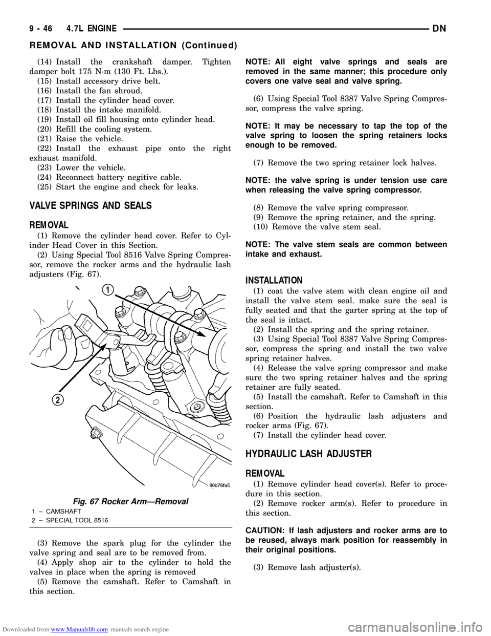
(2) Using Special Tool 8516 Valve Spring Compres-
sor, remove the rocker arms and the hydraulic lash
adjusters (Fig. 67).
(3) Remove the spark plug for the cylinder the
valve spring and seal are to be removed from.
(4) Apply shop air to the cylinder to hold the
valves in place when the spring is removed
(5) Remove the camshaft. Refer to Camshaft in
this section.NOTE: All eight valve springs and seals are
removed in the same manner; this procedure only
covers one valve seal and valve spring.
(6) Using Special Tool 8387 Valve Spring Compres-
sor, compress the valve spring.
NOTE: It may be necessary to tap the top of the
valve spring to loosen the spring retainers locks
enough to be removed.
(7) Remove the two spring retainer lock halves.
NOTE: the valve spring is under tension use care
when releasing the valve spring compressor.
(8) Remove the valve spring compressor.
(9) Remove the spring retainer, and the spring.
(10) Remove the valve stem seal.
NOTE: The valve stem seals are common between
intake and exhaust.
INSTALLATION
(1) coat the valve stem with clean engine oil and
install the valve stem seal. make sure the seal is
fully seated and that the garter spring at the top of
the seal is intact.
(2) Install the spring and the spring retainer.
(3) Using Special Tool 8387 Valve Spring Compres-
sor, compress the spring and install the two valve
spring retainer halves.
(4) Release the valve spring compressor and make
sure the two spring retainer halves and the spring
retainer are fully seated.
(5) Install the camshaft. Refer to Camshaft in this
section.
(6) Position the hydraulic lash adjusters and
rocker arms (Fig. 67).
(7) Install the cylinder head cover.
HYDRAULIC LASH ADJUSTER
REMOVAL
(1) Remove cylinder head cover(s). Refer to proce-
dure in this section.
(2) Remove rocker arm(s). Refer to procedure in
this section.
CAUTION: If lash adjusters and rocker arms are to
be reused, always mark position for reassembly in
their original positions.
(3) Remove lash adjuster(s).
Fig. 67 Rocker ArmÐRemoval
1 ± CAMSHAFT
2 ± SPECIAL TOOL 8516
9 - 46 4.7L ENGINEDN
REMOVAL AND INSTALLATION (Continued)
Page 50 of 193
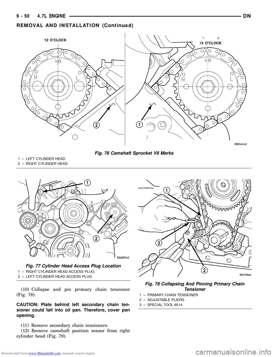
Downloaded from www.Manualslib.com manuals search engine (10) Collapse and pin primary chain tensioner
(Fig. 78).
CAUTION: Plate behind left secondary chain ten-
sioner could fall into oil pan. Therefore, cover pan
opening.
(11) Remove secondary chain tensioners.
(12) Remove camshaft position sensor from right
cylinder head (Fig. 79).
Fig. 76 Camshaft Sprocket V8 Marks
1 ± LEFT CYLINDER HEAD
2 ± RIGHT CYLINDER HEAD
Fig. 77 Cylinder Head Access Plug Location
1 ± RIGHT CYLINDER HEAD ACCESS PLUG
2 ± LEFT CYLINDER HEAD ACCESS PLUG
Fig. 78 Collapsing And Pinning Primary Chain
Tensioner
1 ± PRIMARY CHAIN TENSIONER
2 ± ADJUSTABLE PLIERS
3 ± SPECIAL TOOL 8514
9 - 50 4.7L ENGINEDN
REMOVAL AND INSTALLATION (Continued)