Rear end DODGE DURANGO 1999 1.G Owner's Manual
[x] Cancel search | Manufacturer: DODGE, Model Year: 1999, Model line: DURANGO, Model: DODGE DURANGO 1999 1.GPages: 193, PDF Size: 5.65 MB
Page 146 of 193
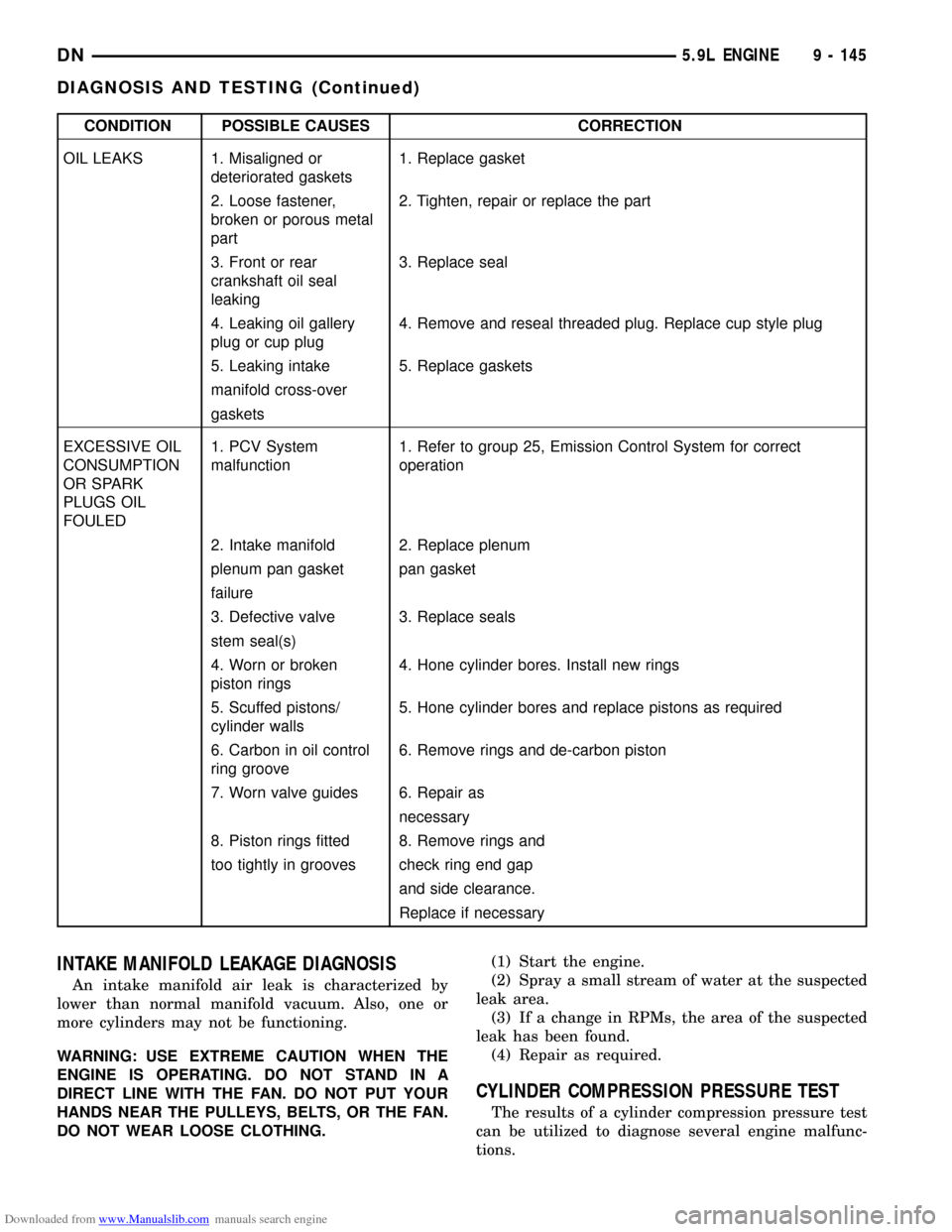
Downloaded from www.Manualslib.com manuals search engine CONDITION POSSIBLE CAUSES CORRECTION
OIL LEAKS 1. Misaligned or
deteriorated gaskets1. Replace gasket
2. Loose fastener,
broken or porous metal
part2. Tighten, repair or replace the part
3. Front or rear
crankshaft oil seal
leaking3. Replace seal
4. Leaking oil gallery
plug or cup plug4. Remove and reseal threaded plug. Replace cup style plug
5. Leaking intake 5. Replace gaskets
manifold cross-over
gaskets
EXCESSIVE OIL
CONSUMPTION
OR SPARK
PLUGS OIL
FOULED1. PCV System
malfunction1. Refer to group 25, Emission Control System for correct
operation
2. Intake manifold 2. Replace plenum
plenum pan gasket pan gasket
failure
3. Defective valve 3. Replace seals
stem seal(s)
4. Worn or broken
piston rings4. Hone cylinder bores. Install new rings
5. Scuffed pistons/
cylinder walls5. Hone cylinder bores and replace pistons as required
6. Carbon in oil control
ring groove6. Remove rings and de-carbon piston
7. Worn valve guides 6. Repair as
necessary
8. Piston rings fitted 8. Remove rings and
too tightly in grooves check ring end gap
and side clearance.
Replace if necessary
INTAKE MANIFOLD LEAKAGE DIAGNOSIS
An intake manifold air leak is characterized by
lower than normal manifold vacuum. Also, one or
more cylinders may not be functioning.
WARNING: USE EXTREME CAUTION WHEN THE
ENGINE IS OPERATING. DO NOT STAND IN A
DIRECT LINE WITH THE FAN. DO NOT PUT YOUR
HANDS NEAR THE PULLEYS, BELTS, OR THE FAN.
DO NOT WEAR LOOSE CLOTHING.(1) Start the engine.
(2) Spray a small stream of water at the suspected
leak area.
(3) If a change in RPMs, the area of the suspected
leak has been found.
(4) Repair as required.
CYLINDER COMPRESSION PRESSURE TEST
The results of a cylinder compression pressure test
can be utilized to diagnose several engine malfunc-
tions.
DN5.9L ENGINE 9 - 145
DIAGNOSIS AND TESTING (Continued)
Page 148 of 193
Downloaded from www.Manualslib.com manuals search engine All gauge pressure indications should be equal,
with no more than 25% leakage.
FOR EXAMPLE:At 552 kPa (80 psi) input pres-
sure, a minimum of 414 kPa (60 psi) should be main-
tained in the cylinder.
Refer to the Cylinder Combustion Pressure Leak-
age Test Diagnosis chart.
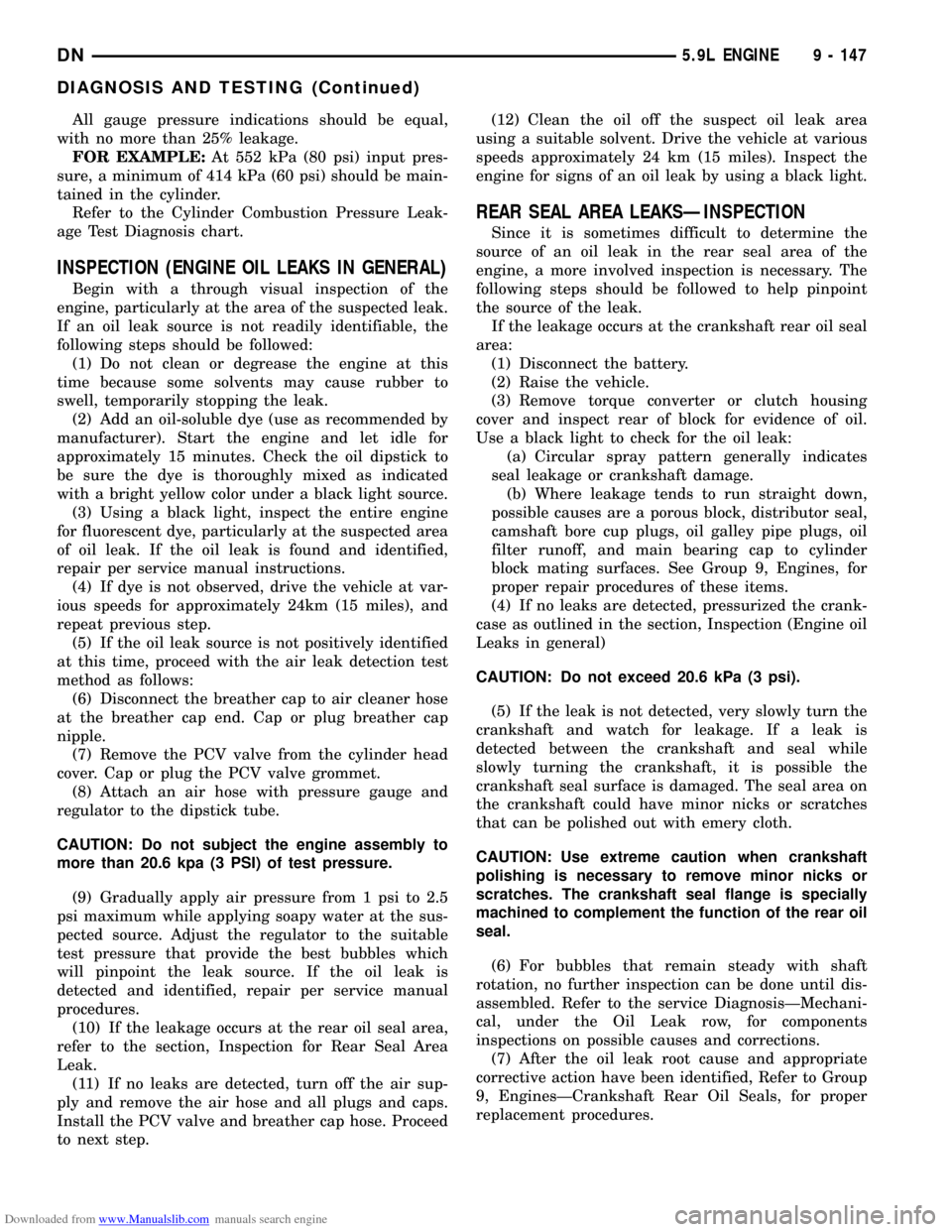
INSPECTION (ENGINE OIL LEAKS IN GENERAL)
Begin with a through visual inspection of the
engine, particularly at the area of the suspected leak.
If an oil leak source is not readily identifiable, the
following steps should be followed:
(1) Do not clean or degrease the engine at this
time because some solvents may cause rubber to
swell, temporarily stopping the leak.
(2) Add an oil-soluble dye (use as recommended by
manufacturer). Start the engine and let idle for
approximately 15 minutes. Check the oil dipstick to
be sure the dye is thoroughly mixed as indicated
with a bright yellow color under a black light source.
(3) Using a black light, inspect the entire engine
for fluorescent dye, particularly at the suspected area
of oil leak. If the oil leak is found and identified,
repair per service manual instructions.
(4) If dye is not observed, drive the vehicle at var-
ious speeds for approximately 24km (15 miles), and
repeat previous step.
(5) If the oil leak source is not positively identified
at this time, proceed with the air leak detection test
method as follows:
(6) Disconnect the breather cap to air cleaner hose
at the breather cap end. Cap or plug breather cap
nipple.
(7) Remove the PCV valve from the cylinder head
cover. Cap or plug the PCV valve grommet.
(8) Attach an air hose with pressure gauge and
regulator to the dipstick tube.
CAUTION: Do not subject the engine assembly to
more than 20.6 kpa (3 PSI) of test pressure.
(9) Gradually apply air pressure from 1 psi to 2.5
psi maximum while applying soapy water at the sus-
pected source. Adjust the regulator to the suitable
test pressure that provide the best bubbles which
will pinpoint the leak source. If the oil leak is
detected and identified, repair per service manual
procedures.
(10) If the leakage occurs at the rear oil seal area,
refer to the section, Inspection for Rear Seal Area
Leak.
(11) If no leaks are detected, turn off the air sup-
ply and remove the air hose and all plugs and caps.
Install the PCV valve and breather cap hose. Proceed
to next step.(12) Clean the oil off the suspect oil leak area
using a suitable solvent. Drive the vehicle at various
speeds approximately 24 km (15 miles). Inspect the
engine for signs of an oil leak by using a black light.
REAR SEAL AREA LEAKSÐINSPECTION
Since it is sometimes difficult to determine the
source of an oil leak in the rear seal area of the
engine, a more involved inspection is necessary. The
following steps should be followed to help pinpoint
the source of the leak.
If the leakage occurs at the crankshaft rear oil seal
area:
(1) Disconnect the battery.
(2) Raise the vehicle.
(3) Remove torque converter or clutch housing
cover and inspect rear of block for evidence of oil.
Use a black light to check for the oil leak:
(a) Circular spray pattern generally indicates
seal leakage or crankshaft damage.
(b) Where leakage tends to run straight down,
possible causes are a porous block, distributor seal,
camshaft bore cup plugs, oil galley pipe plugs, oil
filter runoff, and main bearing cap to cylinder
block mating surfaces. See Group 9, Engines, for
proper repair procedures of these items.
(4) If no leaks are detected, pressurized the crank-
case as outlined in the section, Inspection (Engine oil
Leaks in general)
CAUTION: Do not exceed 20.6 kPa (3 psi).
(5) If the leak is not detected, very slowly turn the
crankshaft and watch for leakage. If a leak is
detected between the crankshaft and seal while
slowly turning the crankshaft, it is possible the
crankshaft seal surface is damaged. The seal area on
the crankshaft could have minor nicks or scratches
that can be polished out with emery cloth.
CAUTION: Use extreme caution when crankshaft
polishing is necessary to remove minor nicks or
scratches. The crankshaft seal flange is specially
machined to complement the function of the rear oil
seal.
(6) For bubbles that remain steady with shaft
rotation, no further inspection can be done until dis-
assembled. Refer to the service DiagnosisÐMechani-
cal, under the Oil Leak row, for components
inspections on possible causes and corrections.
(7) After the oil leak root cause and appropriate
corrective action have been identified, Refer to Group
9, EnginesÐCrankshaft Rear Oil Seals, for proper
replacement procedures.
DN5.9L ENGINE 9 - 147
DIAGNOSIS AND TESTING (Continued)
Page 164 of 193
Downloaded from www.Manualslib.com manuals search engine INTAKE MANIFOLD
REMOVAL
(1) Disconnect the battery negative cable.
(2) Drain the cooling system. Refer to COOLING
SYSTEM.
(3) Remove the A/C compressor. Refer to HEAT-
ING and AIR CONDITIONING.
(4) Remove the generator. Refer to CHARGING
SYSTEM.
(5) Remove the accessory drive bracket.
(6) Remove the air cleaner assembly and air inlet
hose.
(7) Perform the fuel pressure release procedure.
Refer to FUEL SYSTEM.
(8) Disconnect the fuel supply line from the fuel
rail. Refer to FUEL SYSTEM.
(9) Disconnect the accelerator linkage and, if so
equipped, the speed control and transmission kick-
down cables.
(10) Remove the distributor cap and wires.
(11) Disconnect the coil wires.
(12) Disconnect the coolant temperature sending
unit wire.
(13) Disconnect the heater hoses and bypass hose.
(14) Remove the closed crankcase ventilation and
evaporation control systems.
(15) Remove intake manifold bolts.
(16) Lift the intake manifold and throttle body out
of the engine compartment as an assembly.
(17) Remove and discard the flange side gaskets
and the front and rear cross-over gaskets.
(18) Remove the throttle body bolts and lift the
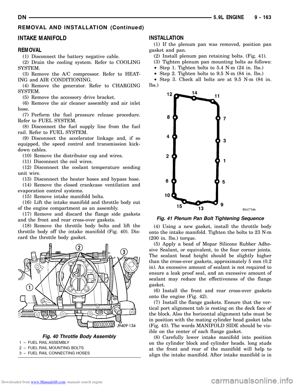
throttle body off the intake manifold (Fig. 40). Dis-
card the throttle body gasket.
INSTALLATION
(1) If the plenum pan was removed, position pan
gasket and pan.
(2) Install plenum pan retaining bolts. (Fig. 41).
(3) Tighten plenum pan mounting bolts as follows:
²Step 1. Tighten bolts to 5.4 N´m (24 in. lbs.)
²Step 2. Tighten bolts to 9.5 N´m (84 in. lbs.)
²Step 3. Check all bolts are at 9.5 N´m (84 in.
lbs.)
(4) Using a new gasket, install the throttle body
onto the intake manifold. Tighten the bolts to 23 N´m
(200 in. lbs.) torque.
(5) Apply a bead of Mopar Silicone Rubber Adhe-
sive Sealant, or equivalent, to the four corner joints.
The sealant bead height should be slightly higher
than the cross-over gaskets, approximately 5 mm (0.2
in). An excessive amount of sealant is not required to
ensure a leak proof seal, and an excessive amount of
sealant may reduce the effectiveness of the flange
gasket.
(6) Install the front and rear cross-over gaskets
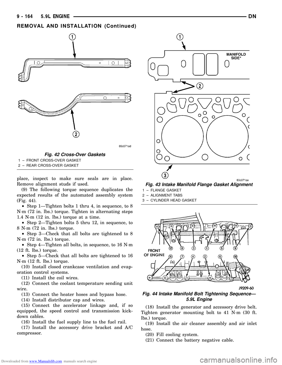
onto the engine (Fig. 42).
(7) Install the flange gaskets. Ensure that the ver-
tical port alignment tab is resting on the deck face of
the block. Also the horizontal alignment tabs must be
in position with the mating cylinder head gasket tabs
(Fig. 43). The words MANIFOLD SIDE should be vis-
ible on the center of each flange gasket.
(8) Carefully lower intake manifold into position
on the cylinder block and cylinder heads. long studs
at the front and rear of the manifold will help to
align the intake manifold. After intake manifold is in
Fig. 40 Throttle Body Assembly
1 ± FUEL RAIL ASSEMBLY
2 ± FUEL RAIL MOUNTING BOLTS
3 ± FUEL RAIL CONNECTING HOSES
Fig. 41 Plenum Pan Bolt Tightening Sequence
DN5.9L ENGINE 9 - 163
REMOVAL AND INSTALLATION (Continued)
Page 165 of 193
Downloaded from www.Manualslib.com manuals search engine place, inspect to make sure seals are in place.
Remove alignment studs if used.
(9) The following torque sequence duplicates the
expected results of the automated assembly system
(Fig. 44).
²Step 1ÐTighten bolts 1 thru 4, in sequence, to 8
N´m (72 in. lbs.) torque. Tighten in alternating steps
1.4 N´m (12 in. lbs.) torque at a time.
²Step 2ÐTighten bolts 5 thru 12, in sequence, to
8 N´m (72 in. lbs.) torque.
²Step 3ÐCheck that all bolts are tightened to 8
N´m (72 in. lbs.) torque.
²Step 4ÐTighten all bolts, in sequence, to 16 N´m
(12 ft. lbs.) torque.
²Step 5ÐCheck that all bolts are tightened to 16
N´m (12 ft. lbs.) torque.
(10) Install closed crankcase ventilation and evap-
oration control systems.
(11) Install the coil wires.
(12) Connect the coolant temperature sending unit
wire.
(13) Connect the heater hoses and bypass hose.
(14) Install distributor cap and wires.
(15) Connect the accelerator linkage and, if so
equipped, the speed control and transmission kick-
down cables.
(16) Install the fuel supply line to the fuel rail.
(17) Install the accessory drive bracket and A/C
compressor.(18) Install the generator and accessory drive belt.
Tighten generator mounting bolt to 41 N´m (30 ft.
lbs.) torque.
(19) Install the air cleaner assembly and air inlet
hose.
(20) Fill cooling system.
(21) Connect the battery negative cable.
Fig. 42 Cross-Over Gaskets
1 ± FRONT CROSS-OVER GASKET
2 ± REAR CROSS-OVER GASKET
Fig. 43 Intake Manifold Flange Gasket Alignment
1 ± FLANGE GASKET
2 ± ALIGNMENT TABS
3 ± CYLINDER HEAD GASKET
Fig. 44 Intake Manifold Bolt Tightening SequenceÐ
5.9L Engine
9 - 164 5.9L ENGINEDN
REMOVAL AND INSTALLATION (Continued)
Page 168 of 193
Downloaded from www.Manualslib.com manuals search engine CYLINDER HEAD
REMOVAL
(1) Disconnect the battery negative cable.
(2) Drain cooling system Refer to COOLING SYS-
TEM.
(3) Remove the intake manifold-to-generator
bracket support rod. Remove the generator.
(4) Remove closed crankcase ventilation system.
(5) Disconnect the evaporation control system.
(6) Remove the air cleaner assembly and air inlet
hose.
(7) Perform fuel system pressure release proce-
dure. Refer to FUEL SYSTEM.
(8) Disconnect the fuel supply line.
(9) Disconnect accelerator linkage and if so
equipped, the speed control and transmission kick-
down cables.
(10) Remove distributor cap and wires.
(11) Disconnect the coil wires.
(12) Disconnect heat indicator sending unit wire.
(13) Disconnect heater hoses and bypass hose.
(14) Remove cylinder head covers and gaskets.
(15) Remove intake manifold and throttle body as
an assembly. Discard the flange side gaskets and the
front and rear cross-over gaskets.
(16) Remove exhaust manifolds.
(17) Remove rocker arm assemblies and push rods.
Identify to ensure installation in original locations.
(18) Remove the head bolts from each cylinder
head and remove cylinder heads. Discard the cylin-
der head gasket.
(19) Remove spark plugs.
INSTALLATION
(1) Position the new cylinder head gaskets onto
the cylinder block.
(2) Position the cylinder heads onto head gaskets
and cylinder block.
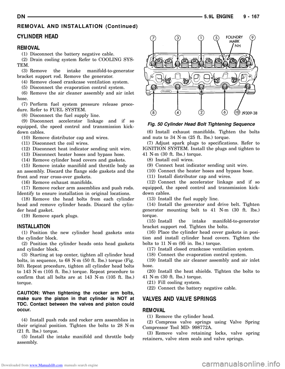
(3) Starting at top center, tighten all cylinder head
bolts, in sequence, to 68 N´m (50 ft. lbs.) torque (Fig.
50). Repeat procedure, tighten all cylinder head bolts
to 143 N´m (105 ft. lbs.) torque. Repeat procedure to
confirm that all bolts are at 143 N´m (105 ft. lbs.)
torque.
CAUTION: When tightening the rocker arm bolts,
make sure the piston in that cylinder is NOT at
TDC. Contact between the valves and piston could
occur.
(4) Install push rods and rocker arm assemblies in
their original position. Tighten the bolts to 28 N´m
(21 ft. lbs.) torque.
(5) Install the intake manifold and throttle body
assembly.(6) Install exhaust manifolds. Tighten the bolts
and nuts to 34 N´m (25 ft. lbs.) torque.
(7) Adjust spark plugs to specifications. Refer to
IGNITION SYSTEM. Install the plugs and tighten to
41 N´m (30 ft. lbs.) torque.
(8) Install coil wires.
(9) Connect heat indicator sending unit wire.
(10) Connect the heater hoses and bypass hose.
(11) Install distributor cap and wires.
(12) Connect the accelerator linkage and if so
equipped, the speed control and transmission kick-
down cables.
(13) Install the fuel supply line.
(14) Install the generator and drive belt. Tighten
generator mounting bolt to 41 N´m (30 ft. lbs.)
torque.
(15) Install the intake manifold-to-generator
bracket support rod. Tighten the bolts.
(16) Place the cylinder head cover gaskets in posi-
tion and install cylinder head covers. Tighten the
bolts to 11 N´m (95 in. lbs.) torque.
(17) Install closed crankcase ventilation system.
(18) Connect the evaporation control system.
(19) Install the air cleaner assembly and air inlet
hose.
(20) Install the heat shields. Tighten the bolts to
41 N´m (30 ft. lbs.) torque.
(21) Fill cooling system.
(22) Connect the battery negative cable.
VALVES AND VALVE SPRINGS
REMOVAL
(1) Remove the cylinder head.
(2) Compress valve springs using Valve Spring
Compressor Tool MD- 998772A.
(3) Remove valve retaining locks, valve spring
retainers, valve stem seals and valve springs.
Fig. 50 Cylinder Head Bolt Tightening Sequence
DN5.9L ENGINE 9 - 167
REMOVAL AND INSTALLATION (Continued)
Page 173 of 193
Downloaded from www.Manualslib.com manuals search engine torque. Top edge of tab should be flat against thrust
plate in order to catch oil for chain lubrication.
(5) Place both camshaft sprocket and crankshaft
sprocket on the bench with timing marks on exact
imaginary center line through both camshaft and
crankshaft bores.
(6) Place timing chain around both sprockets.
(7) Turn crankshaft and camshaft to line up with
keyway location in crankshaft sprocket and in cam-
shaft sprocket.
(8) Lift sprockets and chain (keep sprockets tight
against the chain in position as described).
(9) Slide both sprockets evenly over their respec-
tive shafts and use a straightedge to check alignment
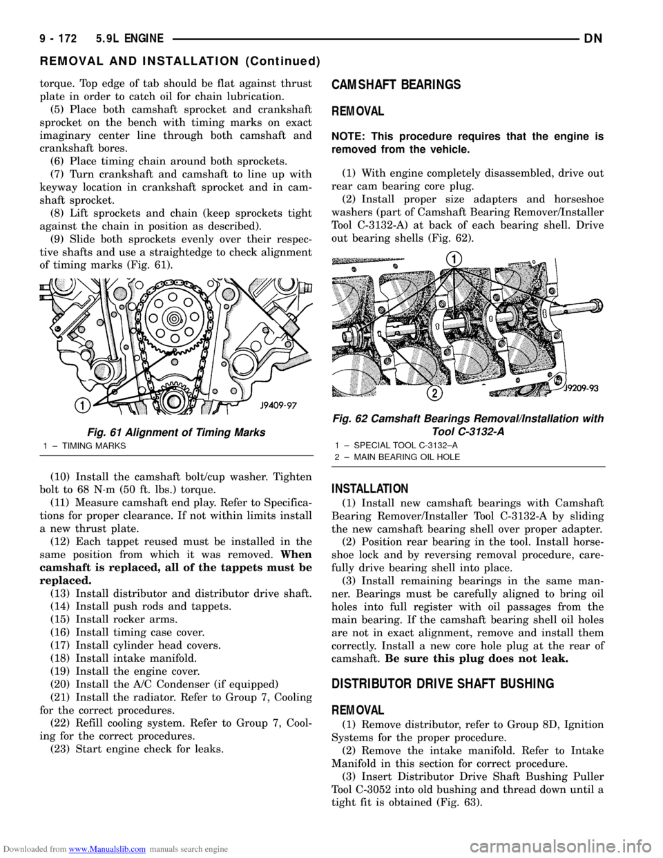
of timing marks (Fig. 61).
(10) Install the camshaft bolt/cup washer. Tighten
bolt to 68 N´m (50 ft. lbs.) torque.
(11) Measure camshaft end play. Refer to Specifica-
tions for proper clearance. If not within limits install
a new thrust plate.
(12) Each tappet reused must be installed in the
same position from which it was removed.When
camshaft is replaced, all of the tappets must be
replaced.
(13) Install distributor and distributor drive shaft.
(14) Install push rods and tappets.
(15) Install rocker arms.
(16) Install timing case cover.
(17) Install cylinder head covers.
(18) Install intake manifold.
(19) Install the engine cover.
(20) Install the A/C Condenser (if equipped)
(21) Install the radiator. Refer to Group 7, Cooling
for the correct procedures.
(22) Refill cooling system. Refer to Group 7, Cool-
ing for the correct procedures.
(23) Start engine check for leaks.CAMSHAFT BEARINGS
REMOVAL
NOTE: This procedure requires that the engine is
removed from the vehicle.
(1) With engine completely disassembled, drive out
rear cam bearing core plug.
(2) Install proper size adapters and horseshoe
washers (part of Camshaft Bearing Remover/Installer
Tool C-3132-A) at back of each bearing shell. Drive
out bearing shells (Fig. 62).
INSTALLATION
(1) Install new camshaft bearings with Camshaft
Bearing Remover/Installer Tool C-3132-A by sliding
the new camshaft bearing shell over proper adapter.
(2) Position rear bearing in the tool. Install horse-
shoe lock and by reversing removal procedure, care-
fully drive bearing shell into place.
(3) Install remaining bearings in the same man-
ner. Bearings must be carefully aligned to bring oil
holes into full register with oil passages from the
main bearing. If the camshaft bearing shell oil holes
are not in exact alignment, remove and install them
correctly. Install a new core hole plug at the rear of
camshaft.Be sure this plug does not leak.
DISTRIBUTOR DRIVE SHAFT BUSHING
REMOVAL
(1) Remove distributor, refer to Group 8D, Ignition
Systems for the proper procedure.
(2) Remove the intake manifold. Refer to Intake
Manifold in this section for correct procedure.
(3) Insert Distributor Drive Shaft Bushing Puller
Tool C-3052 into old bushing and thread down until a
tight fit is obtained (Fig. 63).
Fig. 61 Alignment of Timing Marks
1 ± TIMING MARKS
Fig. 62 Camshaft Bearings Removal/Installation with
Tool C-3132-A
1 ± SPECIAL TOOL C-3132±A
2 ± MAIN BEARING OIL HOLE
9 - 172 5.9L ENGINEDN
REMOVAL AND INSTALLATION (Continued)
Page 177 of 193
Downloaded from www.Manualslib.com manuals search engine INSTALLATION
(1) Be sure that compression ring gaps are stag-
gered so that neither is in-line with oil ring rail gap.
(2) Before installing the ring compressor, make
sure the oil ring expander ends are butted and the
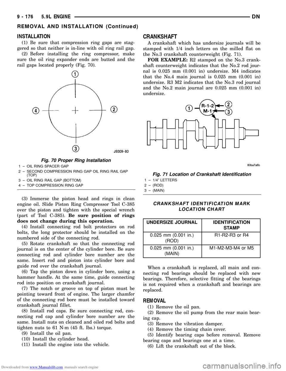
rail gaps located properly (Fig. 70).
(3) Immerse the piston head and rings in clean
engine oil. Slide Piston Ring Compressor Tool C-385
over the piston and tighten with the special wrench
(part of Tool C-385).Be sure position of rings
does not change during this operation.
(4) Install connecting rod bolt protectors on rod
bolts, the long protector should be installed on the
numbered side of the connecting rod.
(5) Rotate crankshaft so that the connecting rod
journal is on the center of the cylinder bore. Be sure
connecting rod and cylinder bore number are the
same. Insert rod and piston into cylinder bore and
guide rod over the crankshaft journal.
(6) Tap the piston down in cylinder bore, using a
hammer handle. At the same time, guide connecting
rod into position on crankshaft journal.
(7) The notch or groove on top of piston must be
pointing toward front of engine. The larger chamfer
of the connecting rod bore must be installed toward
crankshaft journal fillet.
(8) Install rod caps. Be sure connecting rod, con-
necting rod cap and cylinder bore number are the
same. Install nuts on cleaned and oiled rod bolts and
tighten nuts to 61 N´m (45 ft. lbs.) torque.
(9) Install the oil pan.
(10) Install the cylinder head.
(11) Install the engine into the vehicle.
CRANKSHAFT
A crankshaft which has undersize journals will be
stamped with 1/4 inch letters on the milled flat on
the No.3 crankshaft counterweight (Fig. 71).
FOR EXAMPLE:R2 stamped on the No.3 crank-
shaft counterweight indicates that the No.2 rod jour-
nal is 0.025 mm (0.001 in) undersize. M4 indicates
that the No.4 main journal is 0.025 mm (0.001 in)
undersize. R3 M2 indicates that the No.3 rod journal
and the No.2 main journal are 0.025 mm (0.001 in)
undersize.
When a crankshaft is replaced, all main and con-
necting rod bearings should be replaced with new
bearings. Therefore, selective fitting of the bearings
is not required when a crankshaft and bearings are
replaced.
REMOVAL
(1) Remove the oil pan.
(2) Remove the oil pump from the rear main bear-
ing cap.
(3) Remove the vibration damper.
(4) Remove the timing chain cover.
(5) Identify bearing caps before removal. Remove
bearing caps and bearings one at a time.
(6) Lift the crankshaft out of the block.
Fig. 70 Proper Ring Installation
1 ± OIL RING SPACER GAP
2 ± SECOND COMPRESSION RING GAP OIL RING RAIL GAP
(TOP)
3 ± OIL RING RAIL GAP (BOTTOM)
4 ± TOP COMPRESSION RING GAP
Fig. 71 Location of Crankshaft Identification
1 ± 1/4º LETTERS
2 ± (ROD)
3 ± (MAIN)
CRANKSHAFT IDENTIFICATION MARK
LOCATION CHART
UNDERSIZE JOURNAL IDENTIFICATION
STAMP
0.025 mm (0.001 in.)
(ROD)R1-R2-R3 or R4
0.025 mm (0.001 in.)
(MAIN)M1-M2-M3-M4 or M5
9 - 176 5.9L ENGINEDN
REMOVAL AND INSTALLATION (Continued)
Page 183 of 193
Downloaded from www.Manualslib.com manuals search engine ASSEMBLE
(1) Install pump rotors and shaft, using new parts
as required.
(2) Position the oil pump cover onto the pump
body. Tighten cover bolts to 11 N´m (95 in. lbs.)
torque.
(3) Install the relief valve and spring. Insert the
cotter pin.
(4) Tap on a new retainer cap.
(5) Prime oil pump before installation by filling
rotor cavity with engine oil.
CLEANING AND INSPECTION
CYLINDER HEAD COVER
CLEANING
Clean cylinder head cover gasket surface.
Clean head rail, if necessary.
INSPECTION
Inspect cover for distortion and straighten, if nec-
essary.
Check the gasket for use in head cover installation.
If damaged, use a new gasket.
CYLINDER HEAD ASSEMBLY
CLEANING
Clean all surfaces of cylinder block and cylinder
heads.
Clean cylinder block front and rear gasket surfaces
using a suitable solvent.
INSPECTION
Inspect all surfaces with a straightedge if there is
any reason to suspect leakage. If out-of-flatness
exceeds 0.00075 mm/mm (0.00075 inch/inch) times
the span length in inches in any direction, either
replace head or lightly machine the head surface.
FOR EXAMPLE:A 305 mm (12 inch) span is
0.102 mm (0.004 inch) out-of-flat. The allowable out-
of-flat is 305 X 0.00075 (12 X 0.00075) equals 0.23
mm (0.009 inch). This amount of out-of-flat is accept-
able.
The cylinder head surface finish should be
1.78-3.00 microns (70-125 microinches).
PISTON AND CONNECTING ROD ASSEMBLY
INSPECTION
Check the crankshaft connecting rod journal for
excessive wear, taper and scoring.
Check the cylinder block bore for out-of-round,
taper, scoring and scuffing.Check the pistons for taper and elliptical shape
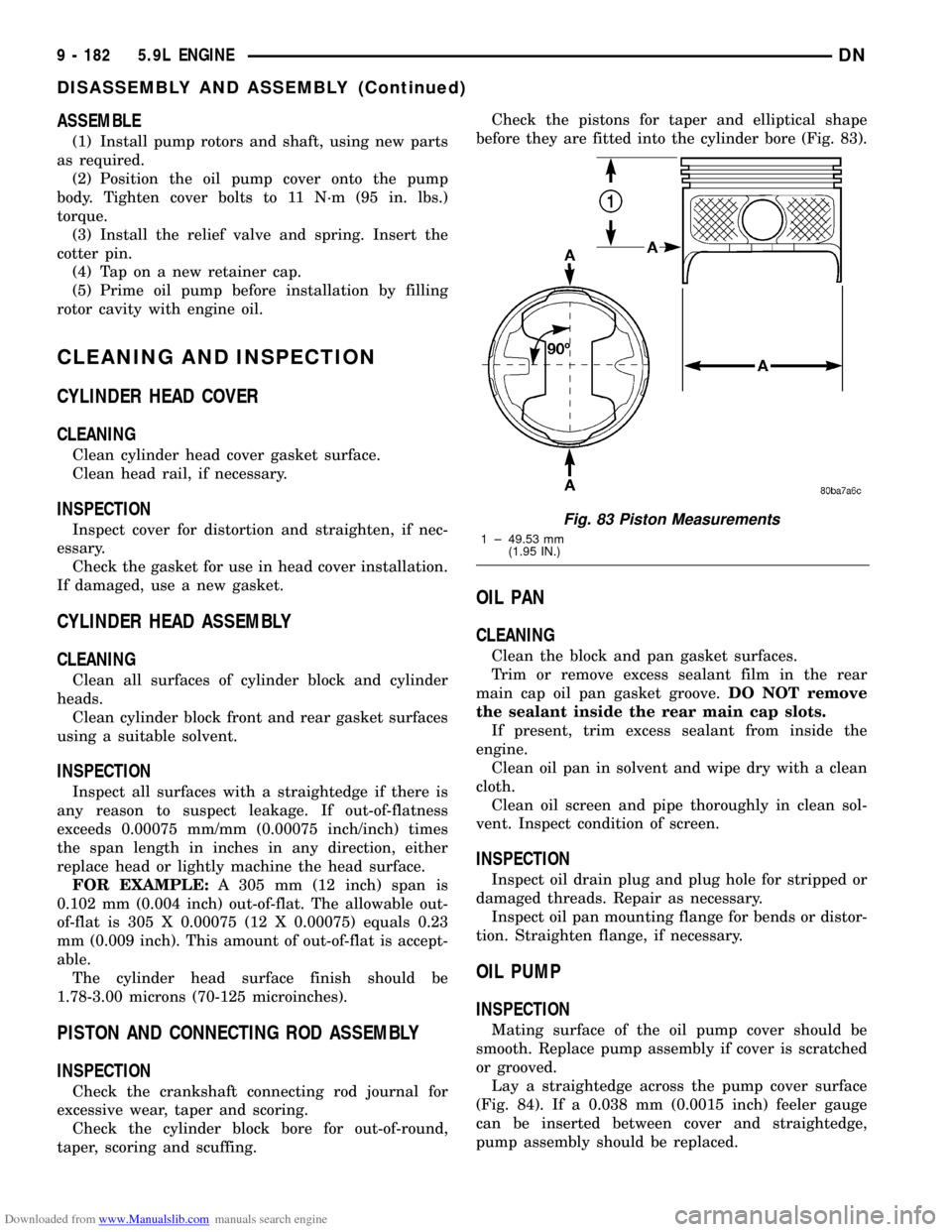
before they are fitted into the cylinder bore (Fig. 83).
OIL PAN
CLEANING
Clean the block and pan gasket surfaces.
Trim or remove excess sealant film in the rear
main cap oil pan gasket groove.DO NOT remove
the sealant inside the rear main cap slots.
If present, trim excess sealant from inside the
engine.
Clean oil pan in solvent and wipe dry with a clean
cloth.
Clean oil screen and pipe thoroughly in clean sol-
vent. Inspect condition of screen.
INSPECTION
Inspect oil drain plug and plug hole for stripped or
damaged threads. Repair as necessary.
Inspect oil pan mounting flange for bends or distor-
tion. Straighten flange, if necessary.
OIL PUMP
INSPECTION
Mating surface of the oil pump cover should be
smooth. Replace pump assembly if cover is scratched
or grooved.
Lay a straightedge across the pump cover surface
(Fig. 84). If a 0.038 mm (0.0015 inch) feeler gauge
can be inserted between cover and straightedge,
pump assembly should be replaced.
Fig. 83 Piston Measurements
1 ± 49.53 mm
(1.95 IN.)
9 - 182 5.9L ENGINEDN
DISASSEMBLY AND ASSEMBLY (Continued)