cylinder DODGE DURANGO 1999 1.G Owner's Manual
[x] Cancel search | Manufacturer: DODGE, Model Year: 1999, Model line: DURANGO, Model: DODGE DURANGO 1999 1.GPages: 193, PDF Size: 5.65 MB
Page 25 of 193
Downloaded from www.Manualslib.com manuals search engine NOTE: Piston rings are installed in the following
order:
²Oil ring expander.
²Upper oil ring side rail.
²Lower oil ring side rail.
²No. 2 Intermediate piston ring.
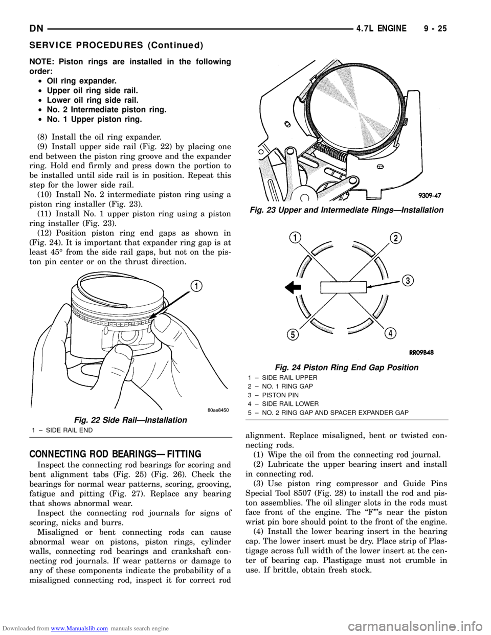
²No. 1 Upper piston ring.
(8) Install the oil ring expander.
(9) Install upper side rail (Fig. 22) by placing one
end between the piston ring groove and the expander
ring. Hold end firmly and press down the portion to
be installed until side rail is in position. Repeat this
step for the lower side rail.
(10) Install No. 2 intermediate piston ring using a
piston ring installer (Fig. 23).
(11) Install No. 1 upper piston ring using a piston
ring installer (Fig. 23).
(12) Position piston ring end gaps as shown in
(Fig. 24). It is important that expander ring gap is at
least 45É from the side rail gaps, but not on the pis-
ton pin center or on the thrust direction.
CONNECTING ROD BEARINGSÐFITTING
Inspect the connecting rod bearings for scoring and
bent alignment tabs (Fig. 25) (Fig. 26). Check the
bearings for normal wear patterns, scoring, grooving,
fatigue and pitting (Fig. 27). Replace any bearing
that shows abnormal wear.
Inspect the connecting rod journals for signs of
scoring, nicks and burrs.
Misaligned or bent connecting rods can cause
abnormal wear on pistons, piston rings, cylinder
walls, connecting rod bearings and crankshaft con-
necting rod journals. If wear patterns or damage to
any of these components indicate the probability of a
misaligned connecting rod, inspect it for correct rodalignment. Replace misaligned, bent or twisted con-
necting rods.
(1) Wipe the oil from the connecting rod journal.
(2) Lubricate the upper bearing insert and install
in connecting rod.
(3) Use piston ring compressor and Guide Pins
Special Tool 8507 (Fig. 28) to install the rod and pis-
ton assemblies. The oil slinger slots in the rods must
face front of the engine. The ªFº's near the piston
wrist pin bore should point to the front of the engine.
(4) Install the lower bearing insert in the bearing
cap. The lower insert must be dry. Place strip of Plas-
tigage across full width of the lower insert at the cen-
ter of bearing cap. Plastigage must not crumble in
use. If brittle, obtain fresh stock.
Fig. 22 Side RailÐInstallation
1 ± SIDE RAIL END
Fig. 23 Upper and Intermediate RingsÐInstallation
Fig. 24 Piston Ring End Gap Position
1 ± SIDE RAIL UPPER
2 ± NO. 1 RING GAP
3 ± PISTON PIN
4 ± SIDE RAIL LOWER
5 ± NO. 2 RING GAP AND SPACER EXPANDER GAP
DN4.7L ENGINE 9 - 25
SERVICE PROCEDURES (Continued)
Page 27 of 193
Downloaded from www.Manualslib.com manuals search engine (9) Repeat the Plastigage measurement to verify
your bearing selection prior to final assembly.
(10) Once you have selected the proper insert,
install the insert and cap. Tighten the connecting rod
bolts to 27 N´m (20 ft. lbs.) plus a 90É turn.
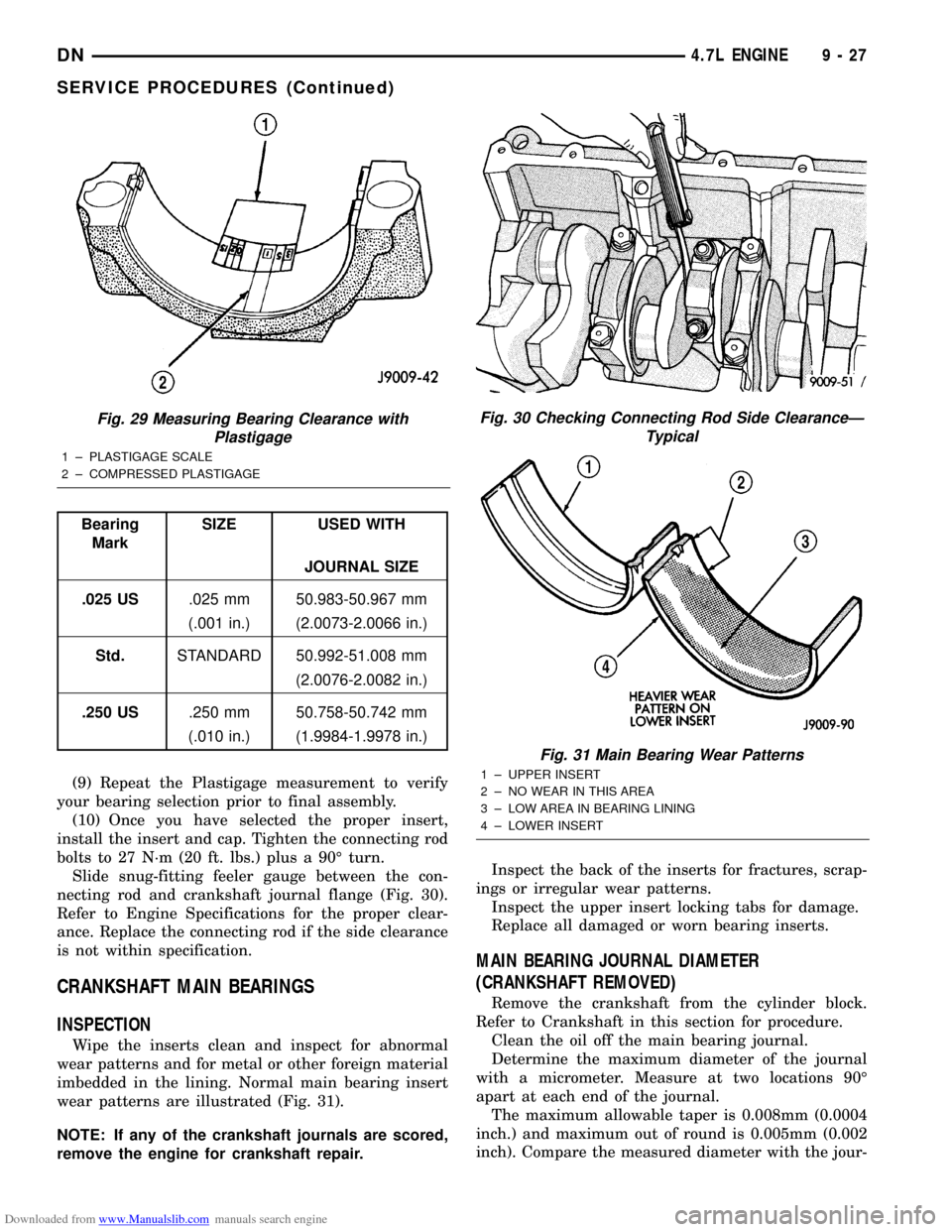
Slide snug-fitting feeler gauge between the con-
necting rod and crankshaft journal flange (Fig. 30).
Refer to Engine Specifications for the proper clear-
ance. Replace the connecting rod if the side clearance
is not within specification.
CRANKSHAFT MAIN BEARINGS
INSPECTION
Wipe the inserts clean and inspect for abnormal
wear patterns and for metal or other foreign material
imbedded in the lining. Normal main bearing insert
wear patterns are illustrated (Fig. 31).
NOTE: If any of the crankshaft journals are scored,
remove the engine for crankshaft repair.Inspect the back of the inserts for fractures, scrap-
ings or irregular wear patterns.
Inspect the upper insert locking tabs for damage.
Replace all damaged or worn bearing inserts.
MAIN BEARING JOURNAL DIAMETER
(CRANKSHAFT REMOVED)
Remove the crankshaft from the cylinder block.
Refer to Crankshaft in this section for procedure.
Clean the oil off the main bearing journal.
Determine the maximum diameter of the journal
with a micrometer. Measure at two locations 90É
apart at each end of the journal.
The maximum allowable taper is 0.008mm (0.0004
inch.) and maximum out of round is 0.005mm (0.002
inch). Compare the measured diameter with the jour-
Fig. 29 Measuring Bearing Clearance with
Plastigage
1 ± PLASTIGAGE SCALE
2 ± COMPRESSED PLASTIGAGE
Bearing
MarkSIZE USED WITH
JOURNAL SIZE
.025 US.025 mm 50.983-50.967 mm
(.001 in.) (2.0073-2.0066 in.)
Std.STANDARD 50.992-51.008 mm
(2.0076-2.0082 in.)
.250 US.250 mm 50.758-50.742 mm
(.010 in.) (1.9984-1.9978 in.)
Fig. 30 Checking Connecting Rod Side ClearanceÐ
Typical
Fig. 31 Main Bearing Wear Patterns
1 ± UPPER INSERT
2 ± NO WEAR IN THIS AREA
3 ± LOW AREA IN BEARING LINING
4 ± LOWER INSERT
DN4.7L ENGINE 9 - 27
SERVICE PROCEDURES (Continued)
Page 28 of 193
Downloaded from www.Manualslib.com manuals search engine nal diameter specification (Main Bearing Fitting
Chart). Select inserts required to obtain the specified
bearing-to-journal clearance.
Install the crankshaft into the cylinder block. Refer
to Crankshaft in this section for procedure.
CRANKSHAFT MAIN BEARING SELECTION
(1) Service main bearings are available in three
grades. The chart below identifies the three service
grades available.
REMOVAL AND INSTALLATION
ENGINE MOUNTSÐLEFT AND RIGHT
REMOVAL
(1) Disconnect the negative cable from the battery.
CAUTION: Remove the fan blade, fan clutch and
fan shroud before raising engine. Failure to do so
may cause damage to the fan blade, fan clutch and
fan shroud.
(2) Remove the fan blade, fan clutch and fan
shroud. Refer to Group 7. for procedure.
(3) Remove the engine oil filter.
(4) Support the engine with a suitable jack and a
block of wood across the full width of the engine oil
pan.
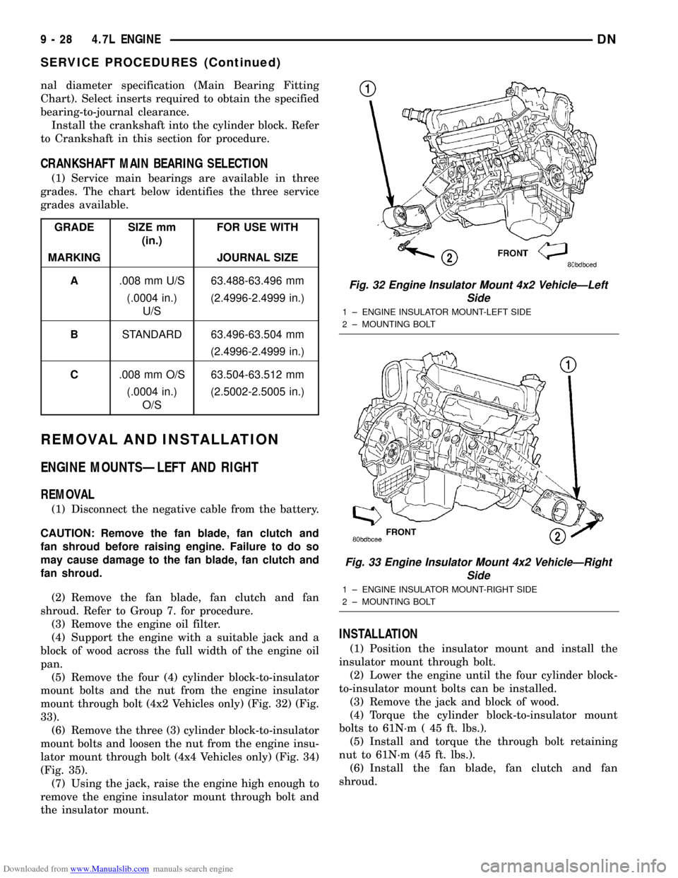
(5) Remove the four (4) cylinder block-to-insulator
mount bolts and the nut from the engine insulator
mount through bolt (4x2 Vehicles only) (Fig. 32) (Fig.
33).
(6) Remove the three (3) cylinder block-to-insulator
mount bolts and loosen the nut from the engine insu-
lator mount through bolt (4x4 Vehicles only) (Fig. 34)
(Fig. 35).
(7) Using the jack, raise the engine high enough to
remove the engine insulator mount through bolt and
the insulator mount.
INSTALLATION
(1) Position the insulator mount and install the
insulator mount through bolt.
(2) Lower the engine until the four cylinder block-
to-insulator mount bolts can be installed.
(3) Remove the jack and block of wood.
(4) Torque the cylinder block-to-insulator mount
bolts to 61N´m ( 45 ft. lbs.).
(5) Install and torque the through bolt retaining
nut to 61N´m (45 ft. lbs.).
(6) Install the fan blade, fan clutch and fan
shroud.
GRADE SIZE mm
(in.)FOR USE WITH
MARKING JOURNAL SIZE
A.008 mm U/S 63.488-63.496 mm
(.0004 in.)
U/S(2.4996-2.4999 in.)
BSTANDARD 63.496-63.504 mm
(2.4996-2.4999 in.)
C.008 mm O/S 63.504-63.512 mm
(.0004 in.)
O/S(2.5002-2.5005 in.)
Fig. 32 Engine Insulator Mount 4x2 VehicleÐLeft
Side
1 ± ENGINE INSULATOR MOUNT-LEFT SIDE
2 ± MOUNTING BOLT
Fig. 33 Engine Insulator Mount 4x2 VehicleÐRight
Side
1 ± ENGINE INSULATOR MOUNT-RIGHT SIDE
2 ± MOUNTING BOLT
9 - 28 4.7L ENGINEDN
SERVICE PROCEDURES (Continued)
Page 32 of 193
Downloaded from www.Manualslib.com manuals search engine ²Throttle Position (TPS) Switch
²Idle Air Control (IAC) Motor
²Engine Oil Pressure Switch
²Engine Coolant Temperature (ECT) Sensor
²Manifold absolute pressure (MAP) Sensor
²Camshaft Position (CMP) Sensor
²Coil Over Plugs
(31) Disconnect the vacuum lines at the throttle
body and intake manifold.
(32) Release fuel rail pressure then disconnect the
fuel supply quick connect fitting at the fuel rail.
Refer toFUEL SYSTEM for procedure.
(33) Remove power steering pump and position out
of the way.
(34) Install Special Tools 8400 Lifting Studs, into
the cylinder heads.
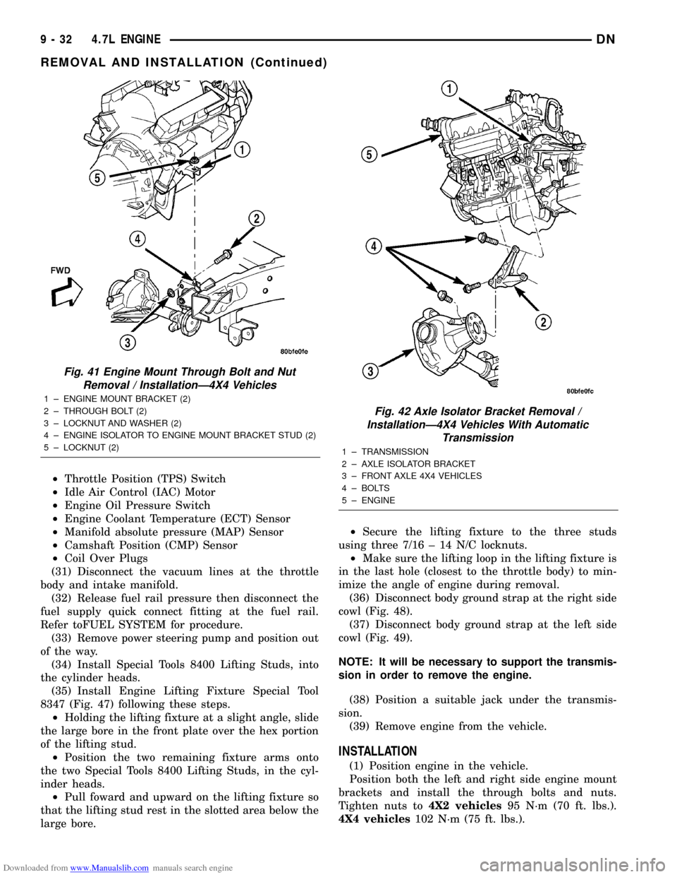
(35) Install Engine Lifting Fixture Special Tool
8347 (Fig. 47) following these steps.
²Holding the lifting fixture at a slight angle, slide
the large bore in the front plate over the hex portion
of the lifting stud.
²Position the two remaining fixture arms onto
the two Special Tools 8400 Lifting Studs, in the cyl-
inder heads.
²Pull foward and upward on the lifting fixture so
that the lifting stud rest in the slotted area below the
large bore.²Secure the lifting fixture to the three studs
using three 7/16 ± 14 N/C locknuts.
²Make sure the lifting loop in the lifting fixture is
in the last hole (closest to the throttle body) to min-
imize the angle of engine during removal.
(36) Disconnect body ground strap at the right side
cowl (Fig. 48).
(37) Disconnect body ground strap at the left side
cowl (Fig. 49).
NOTE: It will be necessary to support the transmis-
sion in order to remove the engine.
(38) Position a suitable jack under the transmis-
sion.
(39) Remove engine from the vehicle.
INSTALLATION
(1) Position engine in the vehicle.
Position both the left and right side engine mount
brackets and install the through bolts and nuts.
Tighten nuts to4X2 vehicles95 N´m (70 ft. lbs.).
4X4 vehicles102 N´m (75 ft. lbs.).
Fig. 41 Engine Mount Through Bolt and Nut
Removal / InstallationÐ4X4 Vehicles
1 ± ENGINE MOUNT BRACKET (2)
2 ± THROUGH BOLT (2)
3 ± LOCKNUT AND WASHER (2)
4 ± ENGINE ISOLATOR TO ENGINE MOUNT BRACKET STUD (2)
5 ± LOCKNUT (2)
Fig. 42 Axle Isolator Bracket Removal /
InstallationÐ4X4 Vehicles With Automatic
Transmission
1 ± TRANSMISSION
2 ± AXLE ISOLATOR BRACKET
3 ± FRONT AXLE 4X4 VEHICLES
4 ± BOLTS
5 ± ENGINE
9 - 32 4.7L ENGINEDN
REMOVAL AND INSTALLATION (Continued)
Page 33 of 193
Downloaded from www.Manualslib.com manuals search engine (2)4X4 vehiclesInstall locknuts onto the engine
mount brackets. Tighten locknuts to 41 N´m (30 ft.
lbs.).
(3) Remove jack from under the transmission.
(4) Remove Engine Lifting Fixture Special Tool
8347 (Fig. 47).
(5) Remove Special Tools 8400 Lifting Studs.
(6) Position generator wiring behind the oil dip-
stick tube, then install the oil dipstick tube upper
mounting bolt.
(7) Connect both left and right side body ground
straps.(8) Install power steering pump.
(9) Connect fuel supply line quick connect fitting.
(10) Connect the vacuum lines at the throttle body
and intake manifold.
(11) Connect engine harness at the following
points (Fig. 46) :
²Intake Air Temperature (IAT) Sensor
²Idle Air Control (IAC) Motor
²Fuel Injectors
²Throttle Position (TPS) Switch
²Engine Oil Pressure Switch
²Engine Coolant Temperature (ECT) Sensor
²Manifold Absolute Pressure (MAP) Sensor
²Camshaft Position (CMP) Sensor
²Coil Over Plugs
(12) Position and install heater hoses and tubes
onto intake manifold.
(13) Install the heater hoses onto the heater core
and the engine front cover.
(14) Install generator.
(15) Install A/C condenser, radiator and transmis-
sion oil cooler as an assembly.
(16) Connect radiator upper and lower hoses.
(17) Connect the transmission oil cooler lines to
the radiator.
(18) Install accessory drive belt, fan assembly and
shroud.
(19) Install A/C compressor. Tighten the A/C com-
pressor and generator M10 mounting bolts 40±68N´M
(30±50 ft. lbs.) and the M8 bolts 22±34 N´m (200±300
in. lbs.).
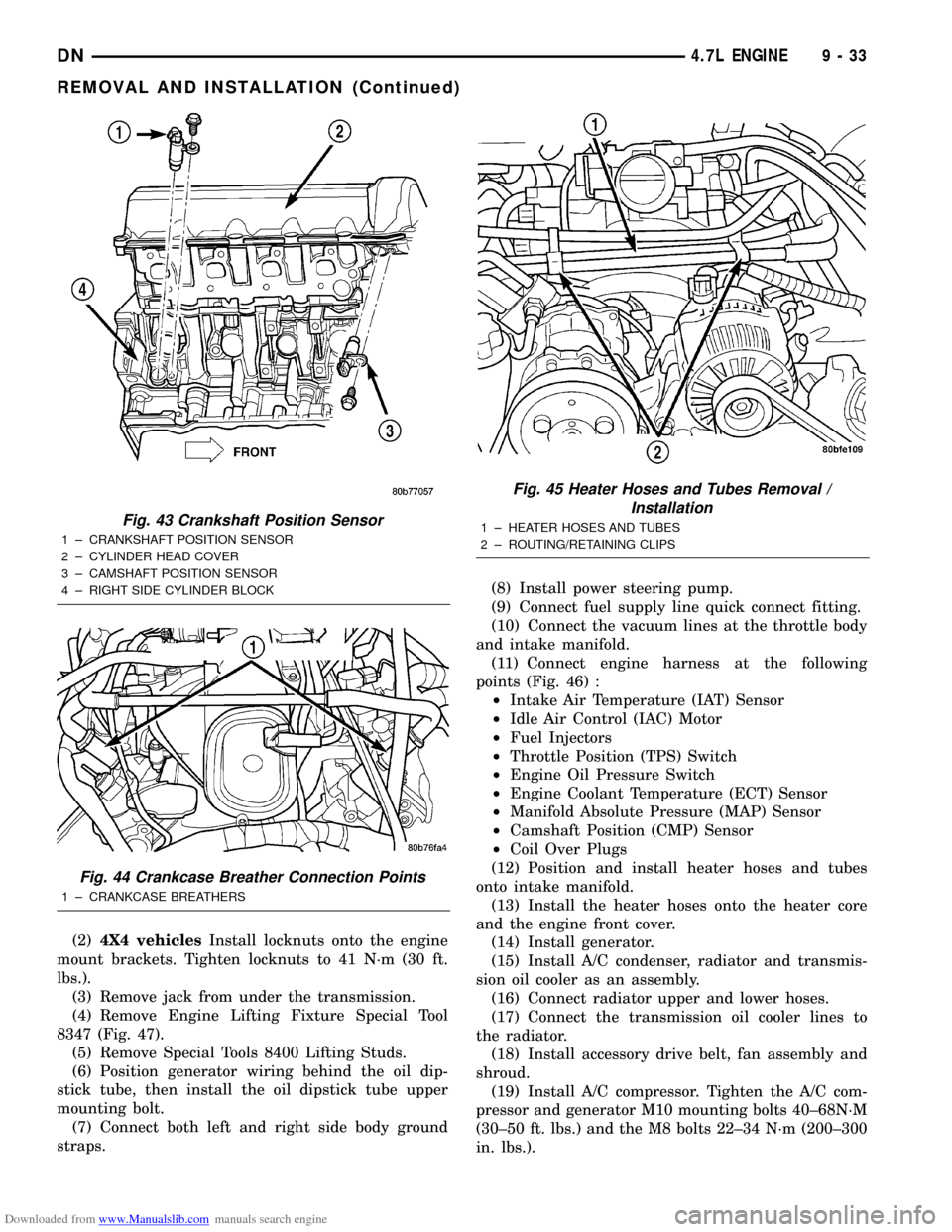
Fig. 43 Crankshaft Position Sensor
1 ± CRANKSHAFT POSITION SENSOR
2 ± CYLINDER HEAD COVER
3 ± CAMSHAFT POSITION SENSOR
4 ± RIGHT SIDE CYLINDER BLOCK
Fig. 44 Crankcase Breather Connection Points
1 ± CRANKCASE BREATHERS
Fig. 45 Heater Hoses and Tubes Removal /
Installation
1 ± HEATER HOSES AND TUBES
2 ± ROUTING/RETAINING CLIPS
DN4.7L ENGINE 9 - 33
REMOVAL AND INSTALLATION (Continued)
Page 38 of 193
Downloaded from www.Manualslib.com manuals search engine (9) Install A/C compressor and fasteners.
(10) Install accessory drive belt.
(11) Install air cleaner assembly, resonator assem-
bly and air inlet hose.
(12) Install battery and connect cables.
(13) Fill cooling system.
LEFT EXHAUST MANIFOLD
REMOVAL
(1) Disconnect negative cable for battery.
(2) Hoist vehicle.
(3) Disconnect exhaust pipe at manifold.
(4) Lower vehicle.
(5) Remove the front two exhaust heat shield
retaining fasteners. Raise vehicle and remove the
fasteners at rear of heat shield.
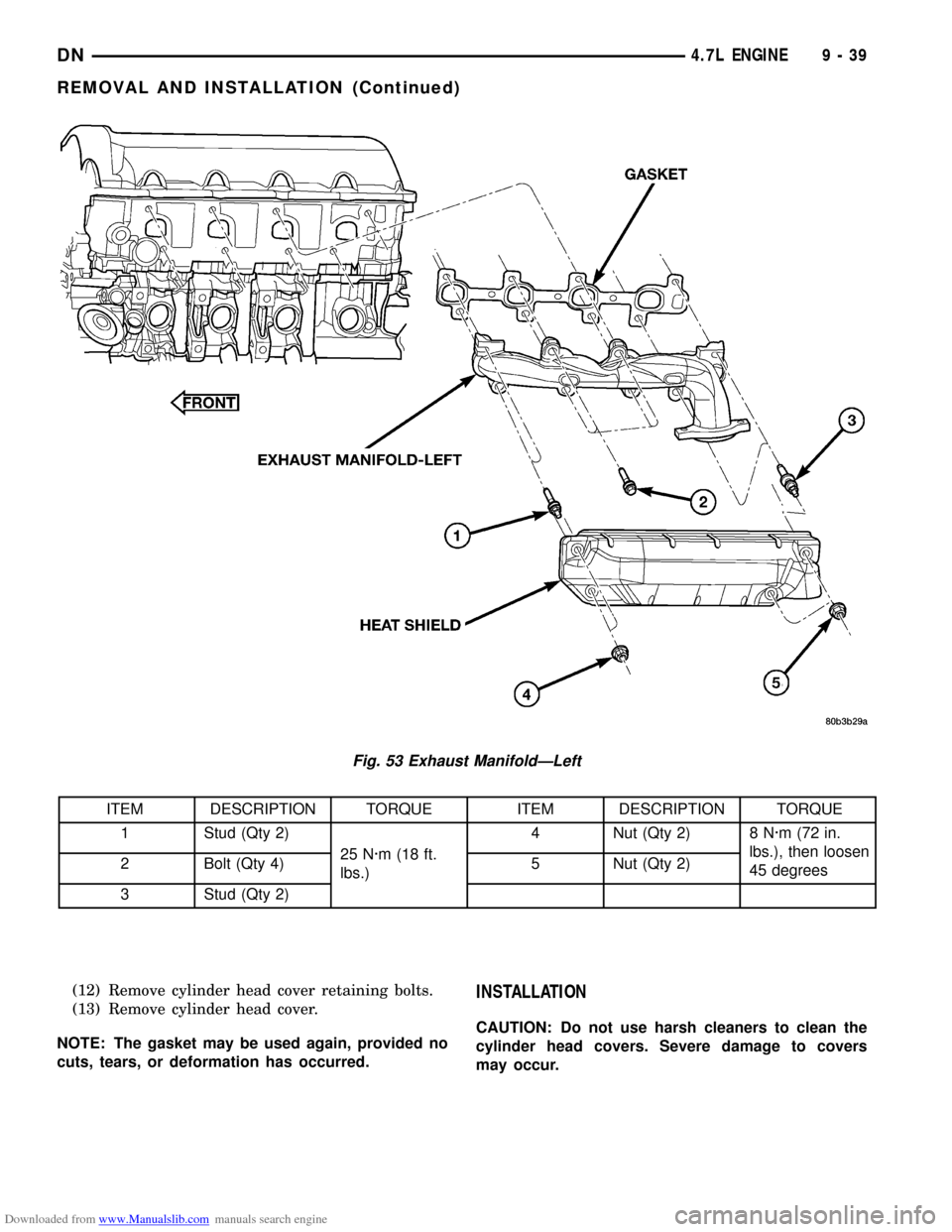
(6) Remove heat shield (Fig. 53).
(7) Lower vehicle and remove the upper exhaust
manifold retaining bolts (Fig. 53).
(8) Raise vehicle and remove the lower exhaust
manifold retaining bolts (Fig. 53).
(9) Remove exhaust manifold and gasket (Fig. 53).
Manifold is removed from below the engine compart-
ment.
INSTALLATION
(1) Install exhaust manifold and gasket from below
engine compartment.
(2) Install lower exhaust manifold fasteners (Fig.
53). DO NOT tighten until all fasteners are in place.
(3) Lower vehicle and install upper exhaust mani-
fold fasteners (Fig. 53). Tighten all manifold bolts
starting at center and working outward to 25 N´m
(18 ft. lbs.).
CAUTION: Over tightening heat shield fasteners,
may cause shield to distort and/or crack.
(4) Install exhaust manifold heat shield (Fig. 53).
Tighten fasteners to 8 N´m (72 in. lbs.), then loosen
45 degrees.
(5) Connect exhaust pipe to manifold.
(6) Connect negative cable to battery.
CYLINDER HEAD COVER
REMOVAL
LEFT SIDE COVER
(1) Disconnect negative cable from battery.
(2) Remove the resonator assemble and air inlet
hose.
(3) Disconnect injector connectors and un-clip the
injector harness.
(4) Route injector harness in front of cylinder head
cover.(5) Disconnect the left side breather tube and
remove the breather tube.
(6) Remove the cylinder head cover mounting
bolts.
(7) Remove cylinder head cover and gasket.
NOTE: The gasket may be used again, provided no
cuts, tears, or deformation has occurred.
INSTALLATION
CAUTION: Do not use harsh cleaners to clean the
cylinder head covers. Severe damage to covers
may occur.
CAUTION: DO NOT allow other components includ-
ing the wire harness to rest on or against the cylin-
der head cover. Prolonged contact with other
objects may wear a hole in the engine cylinder head
cover.
(1) Clean cylinder head cover and both sealing sur-
faces. Inspect and replace gasket as necessary.
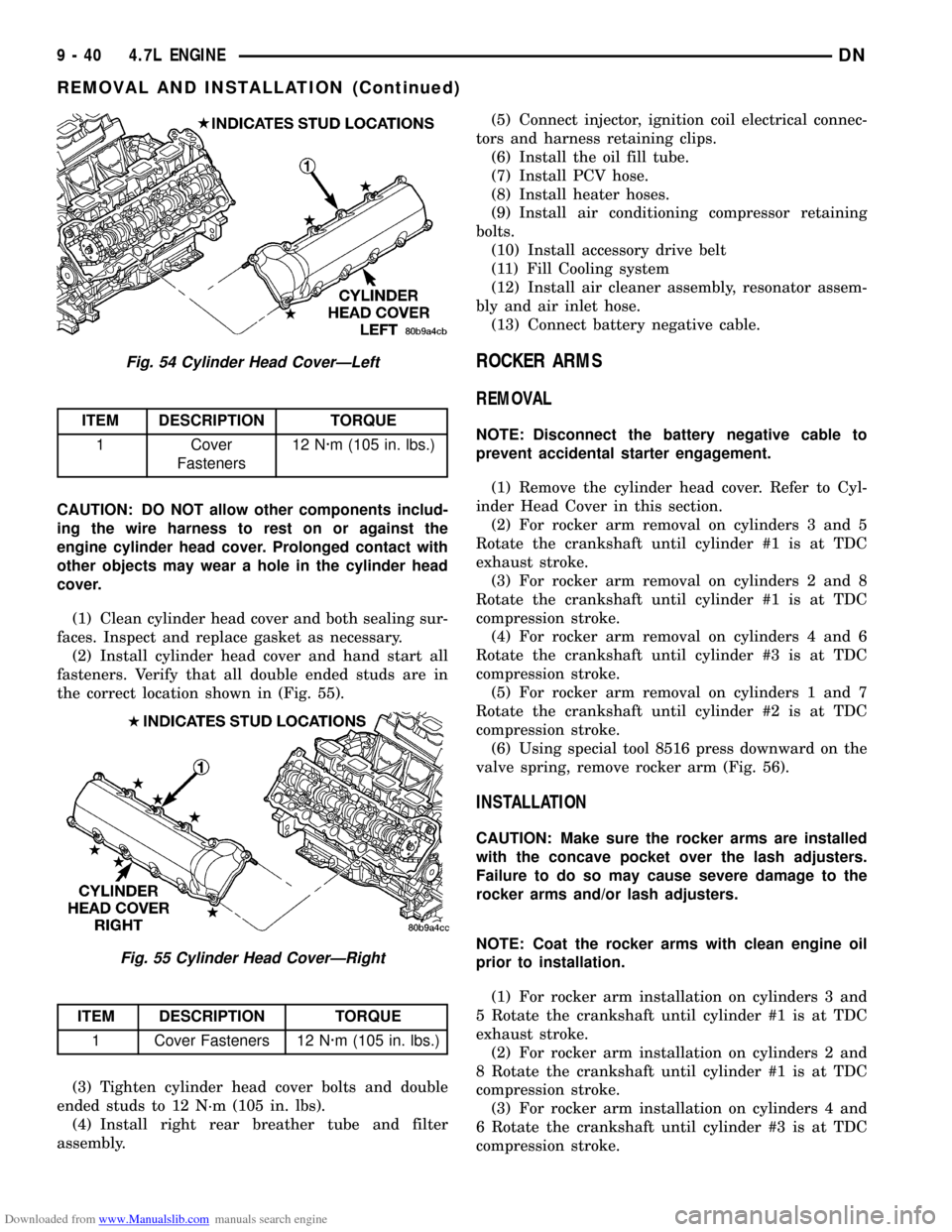
(2) Install cylinder head cover and hand start all
fasteners. Verify that all studs are in the correct loca-
tion shown in (Fig. 54).
(3) Tighten cylinder head cover bolts and double
ended studs to 12 N´m (105 in. lbs.).
(4) Install left side breather and connect breather
tube.
(5) Connect injector electrical connectors and injec-
tor harness retaining clips.
(6) Install the resonator and air inlet hose.
(7) Connect negative cable to battery.
REMOVAL
RIGHT SIDE COVER
(1) Disconnect battery negative cable.
(2) Remove air cleaner assembly, resonator assem-
bly and air inlet hose.
(3) Drain cooling system, below the level of the
heater hoses. Refer to COOLING SYSTEM.
(4) Remove accessory drive belt.
(5) Remove air conditioning compressor retaining
bolts and move compressor to the left.
(6) Remove heater hoses.
(7) Disconnect injector and ignition coil connectors.
(8) Disconnect and remove positive crankcase ven-
tilation (PCV) hose.
(9) Remove oil fill tube.
(10) Un-clip injector and ignition coil harness and
move away from cylinder head cover.
(11) Remove right rear breather tube and filter
assembly.
9 - 38 4.7L ENGINEDN
REMOVAL AND INSTALLATION (Continued)
Page 39 of 193
Downloaded from www.Manualslib.com manuals search engine (12) Remove cylinder head cover retaining bolts.
(13) Remove cylinder head cover.
NOTE: The gasket may be used again, provided no
cuts, tears, or deformation has occurred.INSTALLATION
CAUTION: Do not use harsh cleaners to clean the
cylinder head covers. Severe damage to covers
may occur.
Fig. 53 Exhaust ManifoldÐLeft
ITEM DESCRIPTION TORQUE ITEM DESCRIPTION TORQUE
1 Stud (Qty 2)
25 N´m (18 ft.
lbs.)4 Nut (Qty 2) 8 N´m (72 in.
lbs.), then loosen
45 degrees 2 Bolt (Qty 4) 5 Nut (Qty 2)
3 Stud (Qty 2)
DN4.7L ENGINE 9 - 39
REMOVAL AND INSTALLATION (Continued)
Page 40 of 193
Downloaded from www.Manualslib.com manuals search engine CAUTION: DO NOT allow other components includ-
ing the wire harness to rest on or against the
engine cylinder head cover. Prolonged contact with
other objects may wear a hole in the cylinder head
cover.
(1) Clean cylinder head cover and both sealing sur-
faces. Inspect and replace gasket as necessary.
(2) Install cylinder head cover and hand start all
fasteners. Verify that all double ended studs are in
the correct location shown in (Fig. 55).
(3) Tighten cylinder head cover bolts and double
ended studs to 12 N´m (105 in. lbs).
(4) Install right rear breather tube and filter
assembly.(5) Connect injector, ignition coil electrical connec-
tors and harness retaining clips.
(6) Install the oil fill tube.
(7) Install PCV hose.
(8) Install heater hoses.
(9) Install air conditioning compressor retaining
bolts.
(10) Install accessory drive belt
(11) Fill Cooling system
(12) Install air cleaner assembly, resonator assem-
bly and air inlet hose.
(13) Connect battery negative cable.
ROCKER ARMS
REMOVAL
NOTE: Disconnect the battery negative cable to
prevent accidental starter engagement.
(1) Remove the cylinder head cover. Refer to Cyl-
inder Head Cover in this section.
(2) For rocker arm removal on cylinders 3 and 5
Rotate the crankshaft until cylinder #1 is at TDC
exhaust stroke.
(3) For rocker arm removal on cylinders 2 and 8
Rotate the crankshaft until cylinder #1 is at TDC
compression stroke.
(4) For rocker arm removal on cylinders 4 and 6
Rotate the crankshaft until cylinder #3 is at TDC
compression stroke.
(5) For rocker arm removal on cylinders 1 and 7
Rotate the crankshaft until cylinder #2 is at TDC
compression stroke.
(6) Using special tool 8516 press downward on the
valve spring, remove rocker arm (Fig. 56).
INSTALLATION
CAUTION: Make sure the rocker arms are installed
with the concave pocket over the lash adjusters.
Failure to do so may cause severe damage to the
rocker arms and/or lash adjusters.
NOTE: Coat the rocker arms with clean engine oil
prior to installation.
(1) For rocker arm installation on cylinders 3 and
5 Rotate the crankshaft until cylinder #1 is at TDC
exhaust stroke.
(2) For rocker arm installation on cylinders 2 and
8 Rotate the crankshaft until cylinder #1 is at TDC
compression stroke.
(3) For rocker arm installation on cylinders 4 and
6 Rotate the crankshaft until cylinder #3 is at TDC
compression stroke.
Fig. 54 Cylinder Head CoverÐLeft
ITEM DESCRIPTION TORQUE
1 Cover
Fasteners12 N´m (105 in. lbs.)
Fig. 55 Cylinder Head CoverÐRight
ITEM DESCRIPTION TORQUE
1 Cover Fasteners 12 N´m (105 in. lbs.)
9 - 40 4.7L ENGINEDN
REMOVAL AND INSTALLATION (Continued)
Page 41 of 193
Downloaded from www.Manualslib.com manuals search engine (4) For rocker arm installation on cylinders 1 and
7 Rotate the crankshaft until cylinder #2 is at TDC
compression stroke.
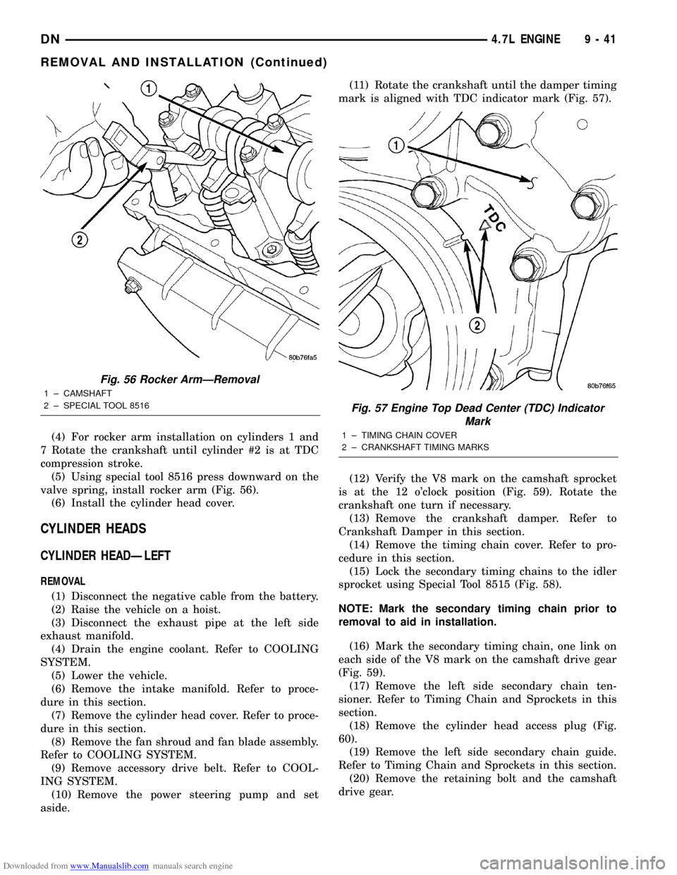
(5) Using special tool 8516 press downward on the
valve spring, install rocker arm (Fig. 56).
(6) Install the cylinder head cover.
CYLINDER HEADS
CYLINDER HEADÐLEFT
REMOVAL
(1) Disconnect the negative cable from the battery.
(2) Raise the vehicle on a hoist.
(3) Disconnect the exhaust pipe at the left side
exhaust manifold.
(4) Drain the engine coolant. Refer to COOLING
SYSTEM.
(5) Lower the vehicle.
(6) Remove the intake manifold. Refer to proce-
dure in this section.
(7) Remove the cylinder head cover. Refer to proce-
dure in this section.
(8) Remove the fan shroud and fan blade assembly.
Refer to COOLING SYSTEM.
(9) Remove accessory drive belt. Refer to COOL-
ING SYSTEM.
(10) Remove the power steering pump and set
aside.(11) Rotate the crankshaft until the damper timing
mark is aligned with TDC indicator mark (Fig. 57).
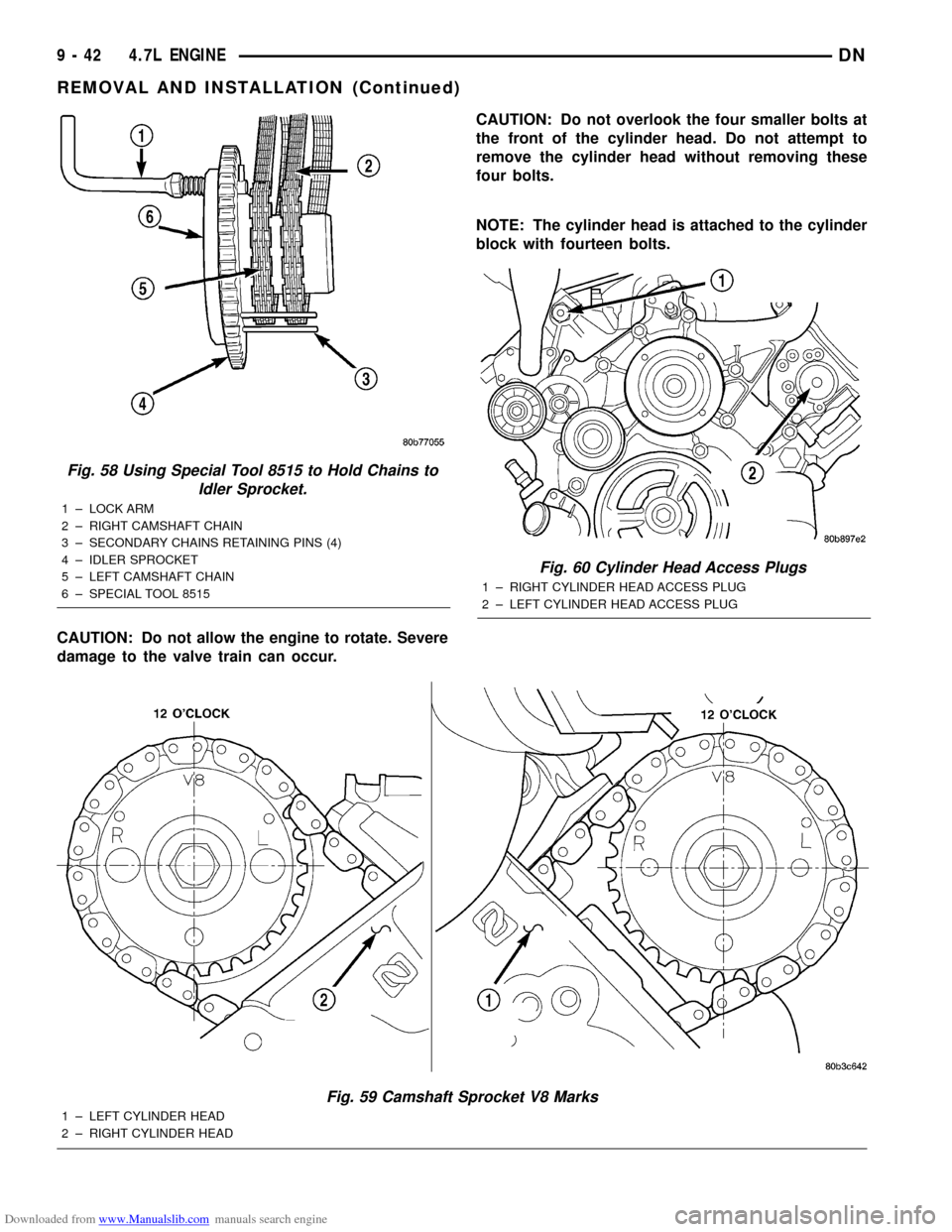
(12) Verify the V8 mark on the camshaft sprocket
is at the 12 o'clock position (Fig. 59). Rotate the
crankshaft one turn if necessary.
(13) Remove the crankshaft damper. Refer to
Crankshaft Damper in this section.
(14) Remove the timing chain cover. Refer to pro-
cedure in this section.
(15) Lock the secondary timing chains to the idler
sprocket using Special Tool 8515 (Fig. 58).
NOTE: Mark the secondary timing chain prior to
removal to aid in installation.
(16) Mark the secondary timing chain, one link on
each side of the V8 mark on the camshaft drive gear
(Fig. 59).
(17) Remove the left side secondary chain ten-
sioner. Refer to Timing Chain and Sprockets in this
section.
(18) Remove the cylinder head access plug (Fig.
60).
(19) Remove the left side secondary chain guide.
Refer to Timing Chain and Sprockets in this section.
(20) Remove the retaining bolt and the camshaft
drive gear.
Fig. 56 Rocker ArmÐRemoval
1 ± CAMSHAFT
2 ± SPECIAL TOOL 8516
Fig. 57 Engine Top Dead Center (TDC) Indicator
Mark
1 ± TIMING CHAIN COVER
2 ± CRANKSHAFT TIMING MARKS
DN4.7L ENGINE 9 - 41
REMOVAL AND INSTALLATION (Continued)
Page 42 of 193
Downloaded from www.Manualslib.com manuals search engine CAUTION: Do not allow the engine to rotate. Severe
damage to the valve train can occur.CAUTION: Do not overlook the four smaller bolts at
the front of the cylinder head. Do not attempt to
remove the cylinder head without removing these
four bolts.
NOTE: The cylinder head is attached to the cylinder
block with fourteen bolts.
Fig. 59 Camshaft Sprocket V8 Marks
1 ± LEFT CYLINDER HEAD
2 ± RIGHT CYLINDER HEAD
Fig. 60 Cylinder Head Access Plugs
1 ± RIGHT CYLINDER HEAD ACCESS PLUG
2 ± LEFT CYLINDER HEAD ACCESS PLUG
Fig. 58 Using Special Tool 8515 to Hold Chains to
Idler Sprocket.
1 ± LOCK ARM
2 ± RIGHT CAMSHAFT CHAIN
3 ± SECONDARY CHAINS RETAINING PINS (4)
4 ± IDLER SPROCKET
5 ± LEFT CAMSHAFT CHAIN
6 ± SPECIAL TOOL 8515
9 - 42 4.7L ENGINEDN
REMOVAL AND INSTALLATION (Continued)