front end DODGE DURANGO 1999 1.G Owner's Manual
[x] Cancel search | Manufacturer: DODGE, Model Year: 1999, Model line: DURANGO, Model: DODGE DURANGO 1999 1.GPages: 193, PDF Size: 5.65 MB
Page 132 of 193
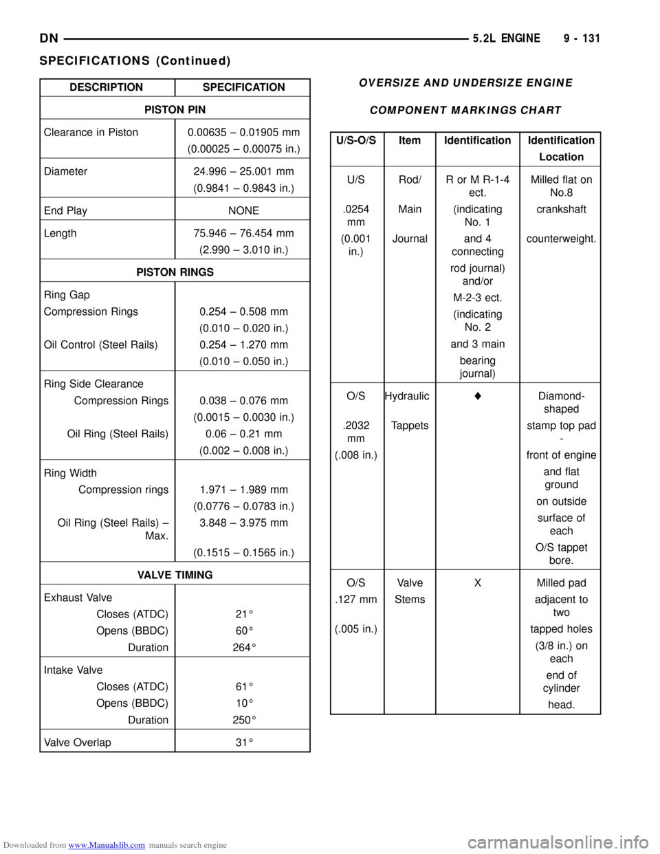
Downloaded from www.Manualslib.com manuals search engine DESCRIPTION SPECIFICATION
PISTON PIN
Clearance in Piston 0.00635 ± 0.01905 mm
(0.00025 ± 0.00075 in.)
Diameter 24.996 ± 25.001 mm
(0.9841 ± 0.9843 in.)
End Play NONE
Length 75.946 ± 76.454 mm
(2.990 ± 3.010 in.)
PISTON RINGS
Ring Gap
Compression Rings 0.254 ± 0.508 mm
(0.010 ± 0.020 in.)
Oil Control (Steel Rails) 0.254 ± 1.270 mm
(0.010 ± 0.050 in.)
Ring Side Clearance
Compression Rings 0.038 ± 0.076 mm
(0.0015 ± 0.0030 in.)
Oil Ring (Steel Rails) 0.06 ± 0.21 mm
(0.002 ± 0.008 in.)
Ring Width
Compression rings 1.971 ± 1.989 mm
(0.0776 ± 0.0783 in.)
Oil Ring (Steel Rails) ±
Max.3.848 ± 3.975 mm
(0.1515 ± 0.1565 in.)
VALVE TIMING
Exhaust Valve
Closes (ATDC) 21É
Opens (BBDC) 60É
Duration 264É
Intake Valve
Closes (ATDC) 61É
Opens (BBDC) 10É
Duration 250É
Valve Overlap 31ÉOVERSIZE AND UNDERSIZE ENGINE
COMPONENT MARKINGS CHART
U/S-O/S Item Identification Identification
Location
U/S Rod/ R or M R-1-4
ect.Milled flat on
No.8
.0254
mmMain (indicating
No. 1crankshaft
(0.001
in.)Journal and 4
connectingcounterweight.
rod journal)
and/or
M-2-3 ect.
(indicating
No. 2
and 3 main
bearing
journal)
O/S HydrauliclDiamond-
shaped
.2032
mmTappets stamp top pad
-
(.008 in.) front of engine
and flat
ground
on outside
surface of
each
O/S tappet
bore.
O/S Valve X Milled pad
.127 mm Stems adjacent to
two
(.005 in.) tapped holes
(3/8 in.) on
each
end of
cylinder
head.
DN5.2L ENGINE 9 - 131
SPECIFICATIONS (Continued)
Page 137 of 193
Downloaded from www.Manualslib.com manuals search engine DESCRIPTION AND OPERATION
ENGINE
DESCRIPTION
The 5.9 Liter (360 CID) eight-cylinder engine is a
V-Type lightweight, single cam, overhead valve
engine with hydraulic roller tappets. This engine is
designed for unleaded fuel.
The engine lubrication system consists of a rotor
type oil pump and a full flow oil filter.
The cylinders are numbered from front to rear; 1,
3, 5, 7 on the left bank and 2, 4, 6, 8 on the right
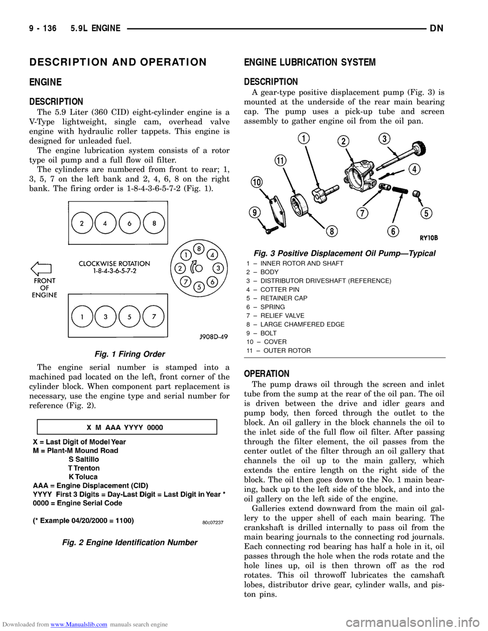
bank. The firing order is 1-8-4-3-6-5-7-2 (Fig. 1).
The engine serial number is stamped into a
machined pad located on the left, front corner of the
cylinder block. When component part replacement is
necessary, use the engine type and serial number for
reference (Fig. 2).
ENGINE LUBRICATION SYSTEM
DESCRIPTION
A gear-type positive displacement pump (Fig. 3) is
mounted at the underside of the rear main bearing
cap. The pump uses a pick-up tube and screen
assembly to gather engine oil from the oil pan.
OPERATION
The pump draws oil through the screen and inlet
tube from the sump at the rear of the oil pan. The oil
is driven between the drive and idler gears and
pump body, then forced through the outlet to the
block. An oil gallery in the block channels the oil to
the inlet side of the full flow oil filter. After passing
through the filter element, the oil passes from the
center outlet of the filter through an oil gallery that
channels the oil up to the main gallery, which
extends the entire length on the right side of the
block. The oil then goes down to the No. 1 main bear-
ing, back up to the left side of the block, and into the
oil gallery on the left side of the engine.
Galleries extend downward from the main oil gal-
lery to the upper shell of each main bearing. The
crankshaft is drilled internally to pass oil from the
main bearing journals to the connecting rod journals.
Each connecting rod bearing has half a hole in it, oil
passes through the hole when the rods rotate and the
hole lines up, oil is then thrown off as the rod
rotates. This oil throwoff lubricates the camshaft
lobes, distributor drive gear, cylinder walls, and pis-
ton pins.
Fig. 1 Firing Order
Fig. 2 Engine Identification Number
Fig. 3 Positive Displacement Oil PumpÐTypical
1 ± INNER ROTOR AND SHAFT
2 ± BODY
3 ± DISTRIBUTOR DRIVESHAFT (REFERENCE)
4 ± COTTER PIN
5 ± RETAINER CAP
6 ± SPRING
7 ± RELIEF VALVE
8 ± LARGE CHAMFERED EDGE
9 ± BOLT
10 ± COVER
11 ± OUTER ROTOR
9 - 136 5.9L ENGINEDN
Page 141 of 193
Downloaded from www.Manualslib.com manuals search engine CYLINDER HEAD COVER GASKET
DESCRIPTION
The cylinder head cover gasket is a steel-backed
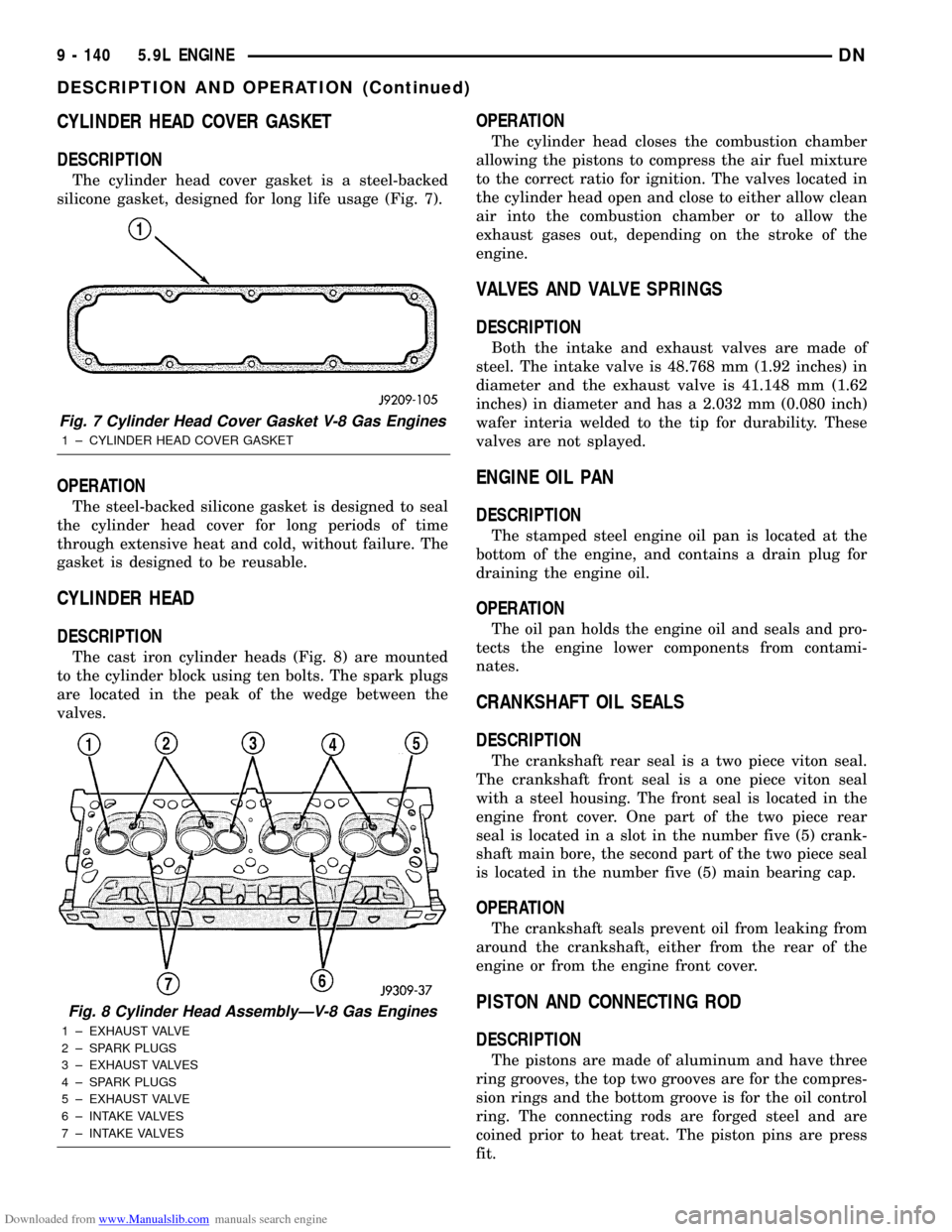
silicone gasket, designed for long life usage (Fig. 7).
OPERATION
The steel-backed silicone gasket is designed to seal
the cylinder head cover for long periods of time
through extensive heat and cold, without failure. The
gasket is designed to be reusable.
CYLINDER HEAD
DESCRIPTION
The cast iron cylinder heads (Fig. 8) are mounted
to the cylinder block using ten bolts. The spark plugs
are located in the peak of the wedge between the
valves.
OPERATION
The cylinder head closes the combustion chamber
allowing the pistons to compress the air fuel mixture
to the correct ratio for ignition. The valves located in
the cylinder head open and close to either allow clean
air into the combustion chamber or to allow the
exhaust gases out, depending on the stroke of the
engine.
VALVES AND VALVE SPRINGS
DESCRIPTION
Both the intake and exhaust valves are made of
steel. The intake valve is 48.768 mm (1.92 inches) in
diameter and the exhaust valve is 41.148 mm (1.62
inches) in diameter and has a 2.032 mm (0.080 inch)
wafer interia welded to the tip for durability. These
valves are not splayed.
ENGINE OIL PAN
DESCRIPTION
The stamped steel engine oil pan is located at the
bottom of the engine, and contains a drain plug for
draining the engine oil.
OPERATION
The oil pan holds the engine oil and seals and pro-
tects the engine lower components from contami-
nates.
CRANKSHAFT OIL SEALS
DESCRIPTION
The crankshaft rear seal is a two piece viton seal.
The crankshaft front seal is a one piece viton seal
with a steel housing. The front seal is located in the
engine front cover. One part of the two piece rear
seal is located in a slot in the number five (5) crank-
shaft main bore, the second part of the two piece seal
is located in the number five (5) main bearing cap.
OPERATION
The crankshaft seals prevent oil from leaking from
around the crankshaft, either from the rear of the
engine or from the engine front cover.
PISTON AND CONNECTING ROD
DESCRIPTION
The pistons are made of aluminum and have three
ring grooves, the top two grooves are for the compres-
sion rings and the bottom groove is for the oil control
ring. The connecting rods are forged steel and are
coined prior to heat treat. The piston pins are press
fit.
Fig. 7 Cylinder Head Cover Gasket V-8 Gas Engines
1 ± CYLINDER HEAD COVER GASKET
Fig. 8 Cylinder Head AssemblyÐV-8 Gas Engines
1 ± EXHAUST VALVE
2 ± SPARK PLUGS
3 ± EXHAUST VALVES
4 ± SPARK PLUGS
5 ± EXHAUST VALVE
6 ± INTAKE VALVES
7 ± INTAKE VALVES
9 - 140 5.9L ENGINEDN
DESCRIPTION AND OPERATION (Continued)
Page 146 of 193
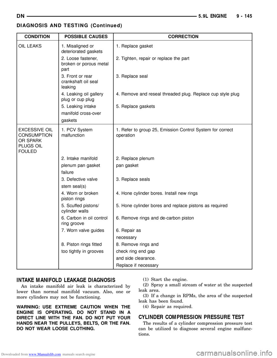
Downloaded from www.Manualslib.com manuals search engine CONDITION POSSIBLE CAUSES CORRECTION
OIL LEAKS 1. Misaligned or
deteriorated gaskets1. Replace gasket
2. Loose fastener,
broken or porous metal
part2. Tighten, repair or replace the part
3. Front or rear
crankshaft oil seal
leaking3. Replace seal
4. Leaking oil gallery
plug or cup plug4. Remove and reseal threaded plug. Replace cup style plug
5. Leaking intake 5. Replace gaskets
manifold cross-over
gaskets
EXCESSIVE OIL
CONSUMPTION
OR SPARK
PLUGS OIL
FOULED1. PCV System
malfunction1. Refer to group 25, Emission Control System for correct
operation
2. Intake manifold 2. Replace plenum
plenum pan gasket pan gasket
failure
3. Defective valve 3. Replace seals
stem seal(s)
4. Worn or broken
piston rings4. Hone cylinder bores. Install new rings
5. Scuffed pistons/
cylinder walls5. Hone cylinder bores and replace pistons as required
6. Carbon in oil control
ring groove6. Remove rings and de-carbon piston
7. Worn valve guides 6. Repair as
necessary
8. Piston rings fitted 8. Remove rings and
too tightly in grooves check ring end gap
and side clearance.
Replace if necessary
INTAKE MANIFOLD LEAKAGE DIAGNOSIS
An intake manifold air leak is characterized by
lower than normal manifold vacuum. Also, one or
more cylinders may not be functioning.
WARNING: USE EXTREME CAUTION WHEN THE
ENGINE IS OPERATING. DO NOT STAND IN A
DIRECT LINE WITH THE FAN. DO NOT PUT YOUR
HANDS NEAR THE PULLEYS, BELTS, OR THE FAN.
DO NOT WEAR LOOSE CLOTHING.(1) Start the engine.
(2) Spray a small stream of water at the suspected
leak area.
(3) If a change in RPMs, the area of the suspected
leak has been found.
(4) Repair as required.
CYLINDER COMPRESSION PRESSURE TEST
The results of a cylinder compression pressure test
can be utilized to diagnose several engine malfunc-
tions.
DN5.9L ENGINE 9 - 145
DIAGNOSIS AND TESTING (Continued)
Page 151 of 193

Downloaded from www.Manualslib.com manuals search engine (2) Check intake manifold bolt torque.
(3) Perform cylinder compression test. Refer to
Cylinder Compression Pressure Test in the Engine
Diagnosis area of this section.
(4) Clean or replace spark plugs as necessary and
adjust gap as specified in Electrical Group 8D.
Tighten to specifications.
(5) Test resistance of spark plug cables. Refer to
Electrical Group 8D, Spark Plug Cables.
(6) Inspect the primary wires. Test coil output volt-
age and primary resistance. Replace parts as neces-
sary. Refer to Electrical Group 8D, for specifications.
(7) Test fuel pump for pressure. Refer to Group 14,
Fuel System Specifications.
(8) The air filter elements should be replaced as
specified in Lubrication and Maintenance, Group 0.
(9) Inspect crankcase ventilation system as out
lined in Group 0, Lubrication and Maintenance. For
emission controls see Group 25, Emission Controls
for service procedures.
(10) Road test vehicle as a final test.
ENGINE OIL
WARNING: NEW OR USED ENGINE OIL CAN BE
IRRITATING TO THE SKIN. AVOID PROLONGED OR
REPEATED SKIN CONTACT WITH ENGINE OIL.
CONTAMINANTS IN USED ENGINE OIL, CAUSED BY
INTERNAL COMBUSTION, CAN BE HAZARDOUS TO
YOUR HEALTH. THOROUGHLY WASH EXPOSED
SKIN WITH SOAP AND WATER. DO NOT WASH
SKIN WITH GASOLINE, DIESEL FUEL, THINNER, OR
SOLVENTS, HEALTH PROBLEMS CAN RESULT. DO
NOT POLLUTE, DISPOSE OF USED ENGINE OIL
PROPERLY.
ENGINE OIL SPECIFICATION
CAUTION: Do not use non-detergent or straight
mineral oil when adding or changing crankcase
lubricant. Engine failure can result.
API SERVICE GRADE CERTIFIED
In gasoline engines, use an engine oil that is API
Service Grade Certified (Fig. 12). Standard engine oil
identification notations have been adopted to aid in
the proper selection of engine oil. The identifying
notations are located on the label of engine oil plastic
bottles and the top of engine oil cans. MOPAR only
provides engine oil that conforms to this certification.
SAE VISCOSITY
An SAE viscosity grade is used to specify the vis-
cosity of engine oil. SAE 10W-30 specifies a multiple
viscosity engine oil. These are specified with a dualSAE viscosity grade which indicates the cold-to-hot
temperature viscosity range. When choosing an
engine oil, consider the range of temperatures the
vehicle will be operated in before the next oil change.
Select an engine oil that is best suited to your area's
particular ambient temperature range and variation
(Fig. 13).
ENERGY CONSERVING OIL
An Energy Conserving type oil is recommended for
gasoline engines. The designation of ENERGY CON-
SERVING is located on the label of an engine oil con-
tainer.
OIL LEVEL INDICATOR (DIPSTICK)
The engine oil level indicator is located at the right
front of the engine, left of the generator on 5.9L
engines (Fig. 14).
CRANKCASE OIL LEVEL INSPECTION
CAUTION: Do not overfill crankcase with engine oil,
oil foaming and oil pressure loss can result.
To ensure proper lubrication of an engine, the
engine oil must be maintained at an acceptable level.
The acceptable levels are indicated between the ADD
and SAFE marks on the engine oil dipstick.
(1) Position vehicle on level surface.
Fig. 12 Engine Oil Container Standard Notations
Fig. 13 Temperature/Engine Oil Viscosity
Recommendation
9 - 150 5.9L ENGINEDN
SERVICE PROCEDURES (Continued)
Page 164 of 193
Downloaded from www.Manualslib.com manuals search engine INTAKE MANIFOLD
REMOVAL
(1) Disconnect the battery negative cable.
(2) Drain the cooling system. Refer to COOLING
SYSTEM.
(3) Remove the A/C compressor. Refer to HEAT-
ING and AIR CONDITIONING.
(4) Remove the generator. Refer to CHARGING
SYSTEM.
(5) Remove the accessory drive bracket.
(6) Remove the air cleaner assembly and air inlet
hose.
(7) Perform the fuel pressure release procedure.
Refer to FUEL SYSTEM.
(8) Disconnect the fuel supply line from the fuel
rail. Refer to FUEL SYSTEM.
(9) Disconnect the accelerator linkage and, if so
equipped, the speed control and transmission kick-
down cables.
(10) Remove the distributor cap and wires.
(11) Disconnect the coil wires.
(12) Disconnect the coolant temperature sending
unit wire.
(13) Disconnect the heater hoses and bypass hose.
(14) Remove the closed crankcase ventilation and
evaporation control systems.
(15) Remove intake manifold bolts.
(16) Lift the intake manifold and throttle body out
of the engine compartment as an assembly.
(17) Remove and discard the flange side gaskets
and the front and rear cross-over gaskets.
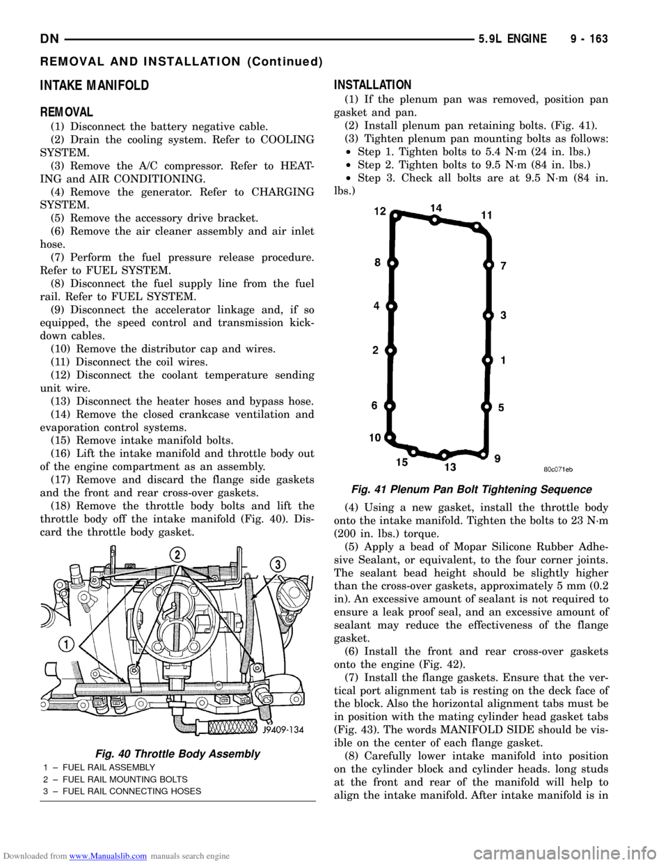
(18) Remove the throttle body bolts and lift the
throttle body off the intake manifold (Fig. 40). Dis-
card the throttle body gasket.
INSTALLATION
(1) If the plenum pan was removed, position pan
gasket and pan.
(2) Install plenum pan retaining bolts. (Fig. 41).
(3) Tighten plenum pan mounting bolts as follows:
²Step 1. Tighten bolts to 5.4 N´m (24 in. lbs.)
²Step 2. Tighten bolts to 9.5 N´m (84 in. lbs.)
²Step 3. Check all bolts are at 9.5 N´m (84 in.
lbs.)
(4) Using a new gasket, install the throttle body
onto the intake manifold. Tighten the bolts to 23 N´m
(200 in. lbs.) torque.
(5) Apply a bead of Mopar Silicone Rubber Adhe-
sive Sealant, or equivalent, to the four corner joints.
The sealant bead height should be slightly higher
than the cross-over gaskets, approximately 5 mm (0.2
in). An excessive amount of sealant is not required to
ensure a leak proof seal, and an excessive amount of
sealant may reduce the effectiveness of the flange
gasket.
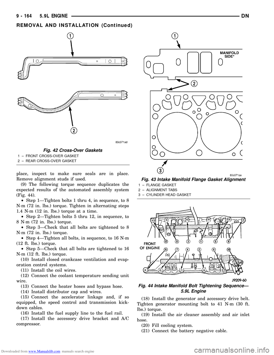
(6) Install the front and rear cross-over gaskets
onto the engine (Fig. 42).
(7) Install the flange gaskets. Ensure that the ver-
tical port alignment tab is resting on the deck face of
the block. Also the horizontal alignment tabs must be
in position with the mating cylinder head gasket tabs
(Fig. 43). The words MANIFOLD SIDE should be vis-
ible on the center of each flange gasket.
(8) Carefully lower intake manifold into position
on the cylinder block and cylinder heads. long studs
at the front and rear of the manifold will help to
align the intake manifold. After intake manifold is in
Fig. 40 Throttle Body Assembly
1 ± FUEL RAIL ASSEMBLY
2 ± FUEL RAIL MOUNTING BOLTS
3 ± FUEL RAIL CONNECTING HOSES
Fig. 41 Plenum Pan Bolt Tightening Sequence
DN5.9L ENGINE 9 - 163
REMOVAL AND INSTALLATION (Continued)
Page 165 of 193
Downloaded from www.Manualslib.com manuals search engine place, inspect to make sure seals are in place.
Remove alignment studs if used.
(9) The following torque sequence duplicates the
expected results of the automated assembly system
(Fig. 44).
²Step 1ÐTighten bolts 1 thru 4, in sequence, to 8
N´m (72 in. lbs.) torque. Tighten in alternating steps
1.4 N´m (12 in. lbs.) torque at a time.
²Step 2ÐTighten bolts 5 thru 12, in sequence, to
8 N´m (72 in. lbs.) torque.
²Step 3ÐCheck that all bolts are tightened to 8
N´m (72 in. lbs.) torque.
²Step 4ÐTighten all bolts, in sequence, to 16 N´m
(12 ft. lbs.) torque.
²Step 5ÐCheck that all bolts are tightened to 16
N´m (12 ft. lbs.) torque.
(10) Install closed crankcase ventilation and evap-
oration control systems.
(11) Install the coil wires.
(12) Connect the coolant temperature sending unit
wire.
(13) Connect the heater hoses and bypass hose.
(14) Install distributor cap and wires.
(15) Connect the accelerator linkage and, if so
equipped, the speed control and transmission kick-
down cables.
(16) Install the fuel supply line to the fuel rail.
(17) Install the accessory drive bracket and A/C
compressor.(18) Install the generator and accessory drive belt.
Tighten generator mounting bolt to 41 N´m (30 ft.
lbs.) torque.
(19) Install the air cleaner assembly and air inlet
hose.
(20) Fill cooling system.
(21) Connect the battery negative cable.
Fig. 42 Cross-Over Gaskets
1 ± FRONT CROSS-OVER GASKET
2 ± REAR CROSS-OVER GASKET
Fig. 43 Intake Manifold Flange Gasket Alignment
1 ± FLANGE GASKET
2 ± ALIGNMENT TABS
3 ± CYLINDER HEAD GASKET
Fig. 44 Intake Manifold Bolt Tightening SequenceÐ
5.9L Engine
9 - 164 5.9L ENGINEDN
REMOVAL AND INSTALLATION (Continued)
Page 168 of 193
Downloaded from www.Manualslib.com manuals search engine CYLINDER HEAD
REMOVAL
(1) Disconnect the battery negative cable.
(2) Drain cooling system Refer to COOLING SYS-
TEM.
(3) Remove the intake manifold-to-generator
bracket support rod. Remove the generator.
(4) Remove closed crankcase ventilation system.
(5) Disconnect the evaporation control system.
(6) Remove the air cleaner assembly and air inlet
hose.
(7) Perform fuel system pressure release proce-
dure. Refer to FUEL SYSTEM.
(8) Disconnect the fuel supply line.
(9) Disconnect accelerator linkage and if so
equipped, the speed control and transmission kick-
down cables.
(10) Remove distributor cap and wires.
(11) Disconnect the coil wires.
(12) Disconnect heat indicator sending unit wire.
(13) Disconnect heater hoses and bypass hose.
(14) Remove cylinder head covers and gaskets.
(15) Remove intake manifold and throttle body as
an assembly. Discard the flange side gaskets and the
front and rear cross-over gaskets.
(16) Remove exhaust manifolds.
(17) Remove rocker arm assemblies and push rods.
Identify to ensure installation in original locations.
(18) Remove the head bolts from each cylinder
head and remove cylinder heads. Discard the cylin-
der head gasket.
(19) Remove spark plugs.
INSTALLATION
(1) Position the new cylinder head gaskets onto
the cylinder block.
(2) Position the cylinder heads onto head gaskets
and cylinder block.
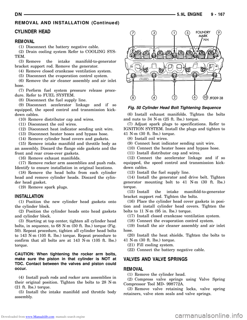
(3) Starting at top center, tighten all cylinder head
bolts, in sequence, to 68 N´m (50 ft. lbs.) torque (Fig.
50). Repeat procedure, tighten all cylinder head bolts
to 143 N´m (105 ft. lbs.) torque. Repeat procedure to
confirm that all bolts are at 143 N´m (105 ft. lbs.)
torque.
CAUTION: When tightening the rocker arm bolts,
make sure the piston in that cylinder is NOT at
TDC. Contact between the valves and piston could
occur.
(4) Install push rods and rocker arm assemblies in
their original position. Tighten the bolts to 28 N´m
(21 ft. lbs.) torque.
(5) Install the intake manifold and throttle body
assembly.(6) Install exhaust manifolds. Tighten the bolts
and nuts to 34 N´m (25 ft. lbs.) torque.
(7) Adjust spark plugs to specifications. Refer to
IGNITION SYSTEM. Install the plugs and tighten to
41 N´m (30 ft. lbs.) torque.
(8) Install coil wires.
(9) Connect heat indicator sending unit wire.
(10) Connect the heater hoses and bypass hose.
(11) Install distributor cap and wires.
(12) Connect the accelerator linkage and if so
equipped, the speed control and transmission kick-
down cables.
(13) Install the fuel supply line.
(14) Install the generator and drive belt. Tighten
generator mounting bolt to 41 N´m (30 ft. lbs.)
torque.
(15) Install the intake manifold-to-generator
bracket support rod. Tighten the bolts.
(16) Place the cylinder head cover gaskets in posi-
tion and install cylinder head covers. Tighten the
bolts to 11 N´m (95 in. lbs.) torque.
(17) Install closed crankcase ventilation system.
(18) Connect the evaporation control system.
(19) Install the air cleaner assembly and air inlet
hose.
(20) Install the heat shields. Tighten the bolts to
41 N´m (30 ft. lbs.) torque.
(21) Fill cooling system.
(22) Connect the battery negative cable.
VALVES AND VALVE SPRINGS
REMOVAL
(1) Remove the cylinder head.
(2) Compress valve springs using Valve Spring
Compressor Tool MD- 998772A.
(3) Remove valve retaining locks, valve spring
retainers, valve stem seals and valve springs.
Fig. 50 Cylinder Head Bolt Tightening Sequence
DN5.9L ENGINE 9 - 167
REMOVAL AND INSTALLATION (Continued)
Page 170 of 193
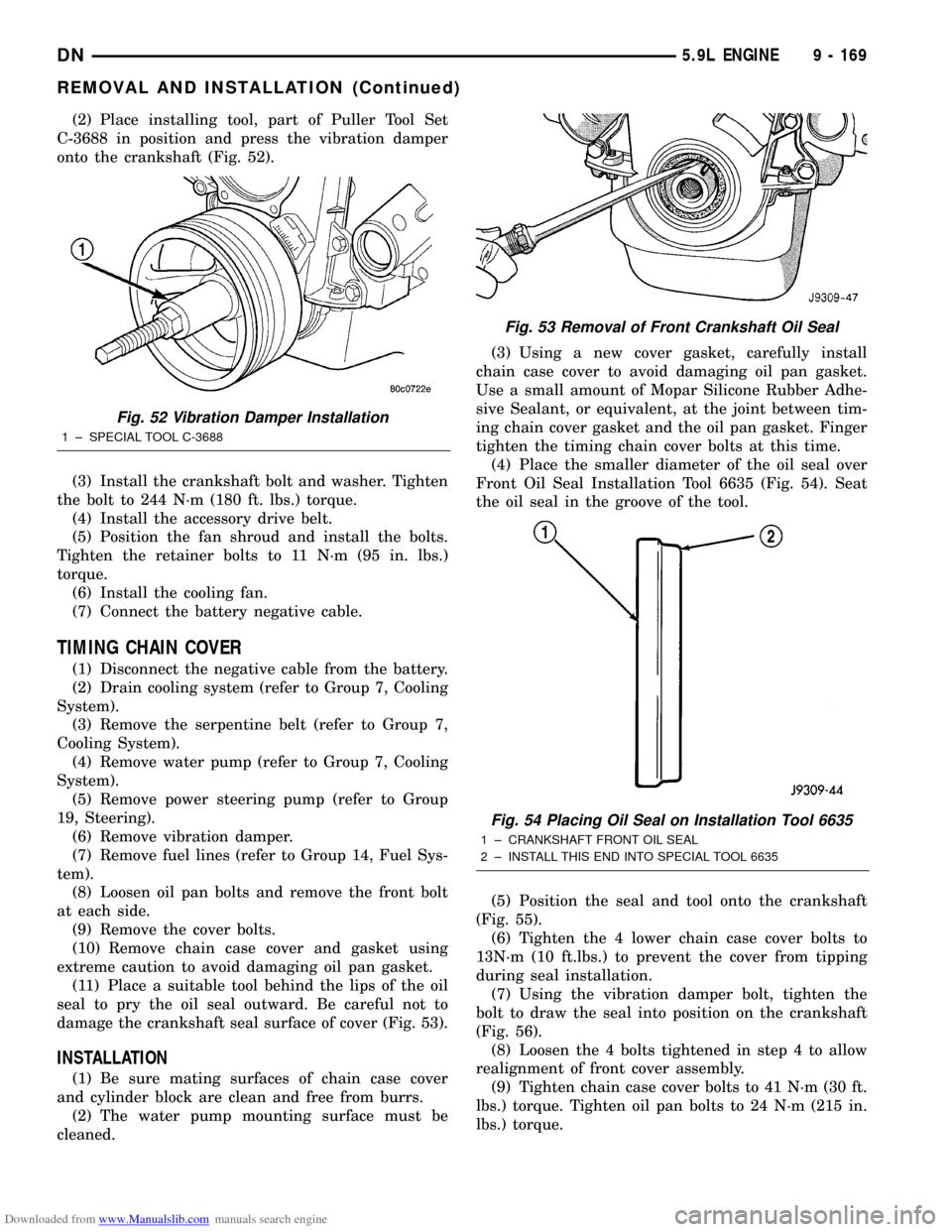
Downloaded from www.Manualslib.com manuals search engine (2) Place installing tool, part of Puller Tool Set
C-3688 in position and press the vibration damper
onto the crankshaft (Fig. 52).
(3) Install the crankshaft bolt and washer. Tighten
the bolt to 244 N´m (180 ft. lbs.) torque.
(4) Install the accessory drive belt.
(5) Position the fan shroud and install the bolts.
Tighten the retainer bolts to 11 N´m (95 in. lbs.)
torque.
(6) Install the cooling fan.
(7) Connect the battery negative cable.
TIMING CHAIN COVER
(1) Disconnect the negative cable from the battery.
(2) Drain cooling system (refer to Group 7, Cooling
System).
(3) Remove the serpentine belt (refer to Group 7,
Cooling System).
(4) Remove water pump (refer to Group 7, Cooling
System).
(5) Remove power steering pump (refer to Group
19, Steering).
(6) Remove vibration damper.
(7) Remove fuel lines (refer to Group 14, Fuel Sys-
tem).
(8) Loosen oil pan bolts and remove the front bolt
at each side.
(9) Remove the cover bolts.
(10) Remove chain case cover and gasket using
extreme caution to avoid damaging oil pan gasket.
(11) Place a suitable tool behind the lips of the oil
seal to pry the oil seal outward. Be careful not to
damage the crankshaft seal surface of cover (Fig. 53).
INSTALLATION
(1) Be sure mating surfaces of chain case cover
and cylinder block are clean and free from burrs.
(2) The water pump mounting surface must be
cleaned.(3) Using a new cover gasket, carefully install
chain case cover to avoid damaging oil pan gasket.
Use a small amount of Mopar Silicone Rubber Adhe-
sive Sealant, or equivalent, at the joint between tim-
ing chain cover gasket and the oil pan gasket. Finger
tighten the timing chain cover bolts at this time.
(4) Place the smaller diameter of the oil seal over
Front Oil Seal Installation Tool 6635 (Fig. 54). Seat
the oil seal in the groove of the tool.
(5) Position the seal and tool onto the crankshaft
(Fig. 55).
(6) Tighten the 4 lower chain case cover bolts to
13N´m (10 ft.lbs.) to prevent the cover from tipping
during seal installation.
(7) Using the vibration damper bolt, tighten the
bolt to draw the seal into position on the crankshaft
(Fig. 56).
(8) Loosen the 4 bolts tightened in step 4 to allow
realignment of front cover assembly.
(9) Tighten chain case cover bolts to 41 N´m (30 ft.
lbs.) torque. Tighten oil pan bolts to 24 N´m (215 in.
lbs.) torque.
Fig. 52 Vibration Damper Installation
1 ± SPECIAL TOOL C-3688
Fig. 53 Removal of Front Crankshaft Oil Seal
Fig. 54 Placing Oil Seal on Installation Tool 6635
1 ± CRANKSHAFT FRONT OIL SEAL
2 ± INSTALL THIS END INTO SPECIAL TOOL 6635
DN5.9L ENGINE 9 - 169
REMOVAL AND INSTALLATION (Continued)
Page 174 of 193
Downloaded from www.Manualslib.com manuals search engine (4) Hold puller screw and tighten puller nut until
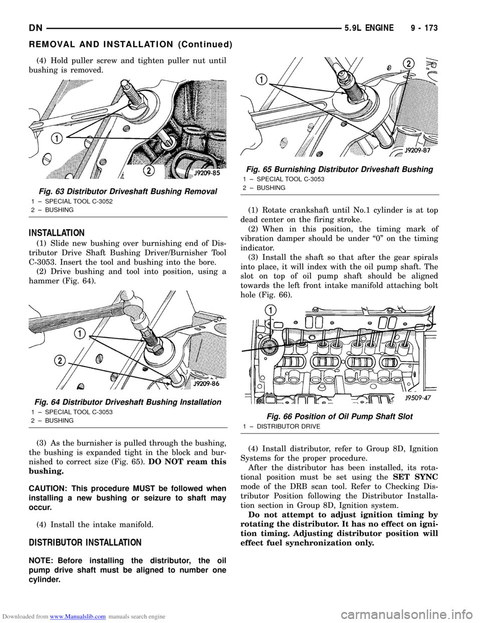
bushing is removed.
INSTALLATION
(1) Slide new bushing over burnishing end of Dis-
tributor Drive Shaft Bushing Driver/Burnisher Tool
C-3053. Insert the tool and bushing into the bore.
(2) Drive bushing and tool into position, using a
hammer (Fig. 64).
(3) As the burnisher is pulled through the bushing,
the bushing is expanded tight in the block and bur-
nished to correct size (Fig. 65).DO NOT ream this
bushing.
CAUTION: This procedure MUST be followed when
installing a new bushing or seizure to shaft may
occur.
(4) Install the intake manifold.
DISTRIBUTOR INSTALLATION
NOTE: Before installing the distributor, the oil
pump drive shaft must be aligned to number one
cylinder.(1) Rotate crankshaft until No.1 cylinder is at top
dead center on the firing stroke.
(2) When in this position, the timing mark of
vibration damper should be under ª0º on the timing
indicator.
(3) Install the shaft so that after the gear spirals
into place, it will index with the oil pump shaft. The
slot on top of oil pump shaft should be aligned
towards the left front intake manifold attaching bolt
hole (Fig. 66).
(4) Install distributor, refer to Group 8D, Ignition
Systems for the proper procedure.
After the distributor has been installed, its rota-
tional position must be set using theSET SYNC
mode of the DRB scan tool. Refer to Checking Dis-
tributor Position following the Distributor Installa-
tion section in Group 8D, Ignition system.
Do not attempt to adjust ignition timing by
rotating the distributor. It has no effect on igni-
tion timing. Adjusting distributor position will
effect fuel synchronization only.
Fig. 63 Distributor Driveshaft Bushing Removal
1 ± SPECIAL TOOL C-3052
2 ± BUSHING
Fig. 64 Distributor Driveshaft Bushing Installation
1 ± SPECIAL TOOL C-3053
2 ± BUSHING
Fig. 65 Burnishing Distributor Driveshaft Bushing
1 ± SPECIAL TOOL C-3053
2 ± BUSHING
Fig. 66 Position of Oil Pump Shaft Slot
1 ± DISTRIBUTOR DRIVE
DN5.9L ENGINE 9 - 173
REMOVAL AND INSTALLATION (Continued)