Ignition system DODGE DURANGO 1999 1.G Workshop Manual
[x] Cancel search | Manufacturer: DODGE, Model Year: 1999, Model line: DURANGO, Model: DODGE DURANGO 1999 1.GPages: 193, PDF Size: 5.65 MB
Page 8 of 193
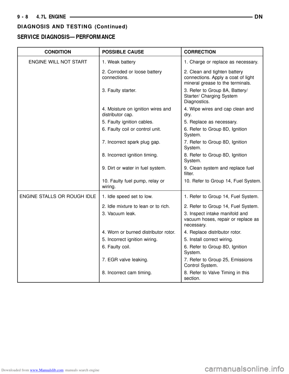
Downloaded from www.Manualslib.com manuals search engine SERVICE DIAGNOSISÐPERFORMANCE
CONDITION POSSIBLE CAUSE CORRECTION
ENGINE WILL NOT START 1. Weak battery 1. Charge or replace as necessary.
2. Corroded or loose battery
connections.2. Clean and tighten battery
connections. Apply a coat of light
mineral grease to the terminals.
3. Faulty starter. 3. Refer to Group 8A, Battery/
Starter/ Charging System
Diagnostics.
4. Moisture on ignition wires and
distributor cap.4. Wipe wires and cap clean and
dry.
5. Faulty ignition cables. 5. Replace as necessary.
6. Faulty coil or control unit. 6. Refer to Group 8D, Ignition
System.
7. Incorrect spark plug gap. 7. Refer to Group 8D, Ignition
System.
8. Incorrect ignition timing. 8. Refer to Group 8D, Ignition
System.
9. Dirt or water in fuel system. 9. Clean system and replace fuel
filter.
10. Faulty fuel pump, relay or
wiring.10. Refer to Group 14, Fuel System.
ENGINE STALLS OR ROUGH IDLE 1. Idle speed set to low. 1. Refer to Group 14, Fuel System.
2. Idle mixture to lean or to rich. 2. Refer to Group 14, Fuel System.
3. Vacuum leak. 3. Inspect intake manifold and
vacuum hoses, repair or replace as
necessary.
4. Worn or burned distributor rotor. 4. Replace distributor rotor.
5. Incorrect ignition wiring. 5. Install correct wiring.
6. Faulty coil. 6. Refer to Group 8D, Ignition
System.
7. EGR valve leaking. 7. Refer to Group 25, Emissions
Control System.
8. Incorrect cam timing. 8. Refer to Valve Timing in this
section.
9 - 8 4.7L ENGINEDN
DIAGNOSIS AND TESTING (Continued)
Page 9 of 193
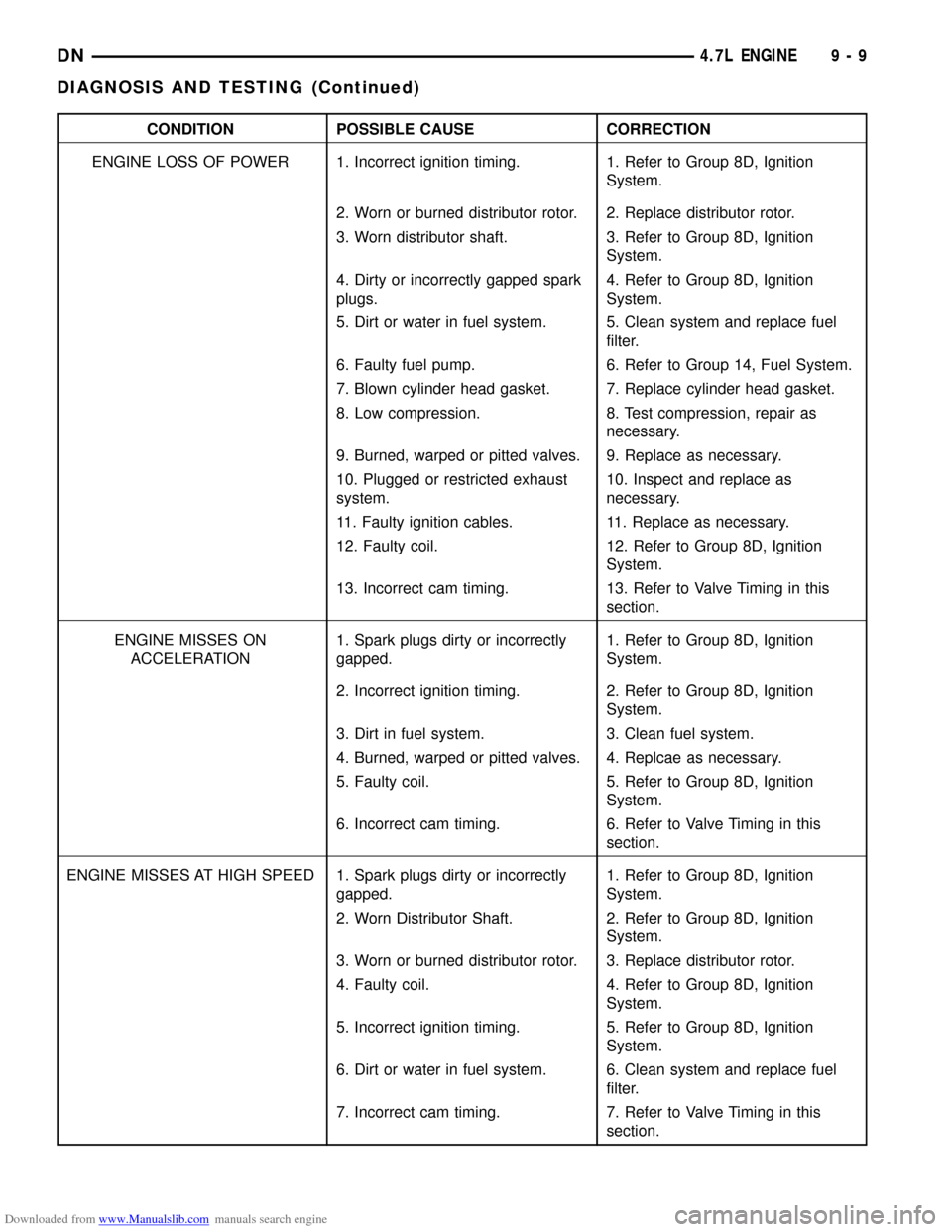
Downloaded from www.Manualslib.com manuals search engine CONDITION POSSIBLE CAUSE CORRECTION
ENGINE LOSS OF POWER 1. Incorrect ignition timing. 1. Refer to Group 8D, Ignition
System.
2. Worn or burned distributor rotor. 2. Replace distributor rotor.
3. Worn distributor shaft. 3. Refer to Group 8D, Ignition
System.
4. Dirty or incorrectly gapped spark
plugs.4. Refer to Group 8D, Ignition
System.
5. Dirt or water in fuel system. 5. Clean system and replace fuel
filter.
6. Faulty fuel pump. 6. Refer to Group 14, Fuel System.
7. Blown cylinder head gasket. 7. Replace cylinder head gasket.
8. Low compression. 8. Test compression, repair as
necessary.
9. Burned, warped or pitted valves. 9. Replace as necessary.
10. Plugged or restricted exhaust
system.10. Inspect and replace as
necessary.
11. Faulty ignition cables. 11. Replace as necessary.
12. Faulty coil. 12. Refer to Group 8D, Ignition
System.
13. Incorrect cam timing. 13. Refer to Valve Timing in this
section.
ENGINE MISSES ON
ACCELERATION1. Spark plugs dirty or incorrectly
gapped.1. Refer to Group 8D, Ignition
System.
2. Incorrect ignition timing. 2. Refer to Group 8D, Ignition
System.
3. Dirt in fuel system. 3. Clean fuel system.
4. Burned, warped or pitted valves. 4. Replcae as necessary.
5. Faulty coil. 5. Refer to Group 8D, Ignition
System.
6. Incorrect cam timing. 6. Refer to Valve Timing in this
section.
ENGINE MISSES AT HIGH SPEED 1. Spark plugs dirty or incorrectly
gapped.1. Refer to Group 8D, Ignition
System.
2. Worn Distributor Shaft. 2. Refer to Group 8D, Ignition
System.
3. Worn or burned distributor rotor. 3. Replace distributor rotor.
4. Faulty coil. 4. Refer to Group 8D, Ignition
System.
5. Incorrect ignition timing. 5. Refer to Group 8D, Ignition
System.
6. Dirt or water in fuel system. 6. Clean system and replace fuel
filter.
7. Incorrect cam timing. 7. Refer to Valve Timing in this
section.
DN4.7L ENGINE 9 - 9
DIAGNOSIS AND TESTING (Continued)
Page 12 of 193
Downloaded from www.Manualslib.com manuals search engine Otherwise the indicated compression pressures may
not be valid for diagnosis purposes.
(1) Clean the spark plug recesses with compressed
air.
(2) Remove the spark plugs.
(3) Secure the throttle in the wide-open position.
(4) Disable the fuel system. (Refer to Group 14,
Fuel System for the correct procedure)
(5) Disconnect the ignition coil.
(6) Insert a compression pressure gauge and rotate
the engine with the engine starter motor for three
revolutions.
(7) Record the compression pressure on the 3rd
revolution. Continue the test for the remaining cylin-
ders.
Refer to Engine Specifications for the correct
engine compression pressures.
CYLINDER HEAD GASKET FAILURE DIAGNOSIS
A cylinder head gasket leak can be located between
adjacent cylinders or between a cylinder and the
adjacent water jacket.
²Possible indications of the cylinder head gasket
leaking between adjacent cylinders are:
²Loss of engine power
²Engine misfiring
²Poor fuel economy
²Possible indications of the cylinder head gasket
leaking between a cylinder and an adjacent water
jacket are:
²Engine overheating
²Loss of coolant
²Excessive steam (white smoke) emitting from
exhaust
²Coolant foaming
CYLINDER-TO-CYLINDER LEAKAGE TEST
To determine if an engine cylinder head gasket is
leaking between adjacent cylinders, follow the proce-
dures in Cylinder Compression Pressure Test in this
section. An engine cylinder head gasket leaking
between adjacent cylinders will result in approxi-
mately a 50±70% reduction in compression pressure.
CYLINDER-TO-WATER JACKET LEAKAGE TEST
WARNING: USE EXTREME CAUTION WHEN THE
ENGINE IS OPERATING WITH COOLANT PRES-
SURE CAP REMOVED.
VISUAL TEST METHOD
With the engine cool, remove the coolant pressure
cap. Start the engine and allow it to warm up until
thermostat opens.
If a large combustion/compression pressure leak
exists, bubbles will be visible in the coolant.COOLING SYSTEM TESTER METHOD
WARNING: WITH COOLING SYSTEM TESTER IN
PLACE, PRESSURE WILL BUILD UP FAST. EXCES-
SIVE PRESSURE BUILT UP, BY CONTINUOUS
ENGINE OPERATION, MUST BE RELEASED TO A
SAFE PRESSURE POINT. NEVER PERMIT PRES-
SURE TO EXCEED 138 kPa (20 psi).
Install Cooling System Tester 7700 or equivalent to
pressure cap neck. Start the engine and observe the
tester's pressure gauge. If gauge pulsates with every
power stroke of a cylinder a combustion pressure
leak is evident.
CHEMICAL TEST METHOD
Combustion leaks into the cooling system can also
be checked by using Bloc-Chek Kit C-3685-A or
equivalent. Perform test following the procedures
supplied with the tool kit.
CYLINDER COMBUSTION PRESSURE LEAKAGE
TEST
The combustion pressure leakage test provides an
accurate means for determining engine condition.
Combustion pressure leakage testing will detect:
²Exhaust and intake valve leaks (improper seat-
ing).
²Leaks between adjacent cylinders or into water
jacket.
²Any causes for combustion/compression pressure
loss.
(1) Check the coolant level and fill as required. DO
NOT install the radiator cap.
(2) Start and operate the engine until it attains
normal operating temperature, then turn the engine
OFF.
(3) Remove the spark plugs.
(4) Remove the oil filler cap.
(5) Remove the air cleaner.
(6)
Calibrate the tester according to the manufacturer's
instructions. The shop air source for testing should main-
tain 483 kPa (70 psi) minimum, 1,379 kPa (200 psi) maxi-
mum and 552 kPa (80 psi) recommended.
(7) Perform the test procedures on each cylinder
according to the tester manufacturer's instructions.
While testing, listen for pressurized air escaping
through the throttle body, tailpipe and oil filler cap
opening. Check for bubbles in the radiator coolant.
All gauge pressure indications should be equal,
with no more than 25% leakage.
FOR EXAMPLE:At 552 kPa (80 psi) input pres-
sure, a minimum of 414 kPa (60 psi) should be main-
tained in the cylinder.
Refer to the Cylinder Combustion Pressure Leak-
age Test Diagnosis chart.
9 - 12 4.7L ENGINEDN
DIAGNOSIS AND TESTING (Continued)
Page 35 of 193
Downloaded from www.Manualslib.com manuals search engine INTAKE MANIFOLD
REMOVAL
(1) Disconnect negative cable from battery.
(2) Remove resonator assembly and air inlet hose.
(3) Disconnect throttle and speed control cables.
(4) Disconnect electrical connectors for the follow-
ing components: Refer to FUEL SYSTEM for compo-
nent locations.
²Manifold Absolute Pressure (MAP) Sensor
²Intake Air Temperature (IAT) Sensor
²Throttle Position (TPS) Sensor
²Coolant Temperature (CTS) Sensor
²Idle Air Control (IAC) Motor
(5) Disconnect vapor purge hose, brake booster
hose, speed control servo hose, positive crankcase
ventilation (PCV) hose.
(6) Disconnect generator electrical connections.
(7) Disconnect air conditioning compressor electri-
cal connections.
(8) Disconnect left and right radio suppressor
straps.
(9) Disconnect and remove ignition coil towers.
(10) Remove top oil dipstick tube retaining bolt
and ground strap.
(11) Bleed fuel system. Refer to FUEL SYSTEM.
(12) Remove fuel rail.
(13) Remove throttle body assembly and mounting
bracket.
(14) Drain cooling system below coolant tempera-
ture level. Refer to COOLING SYSTEM.
(15) Remove the heater hoses from the engine
front cover and the heater core.
(16) Unclip and remove heater hoses and tubes
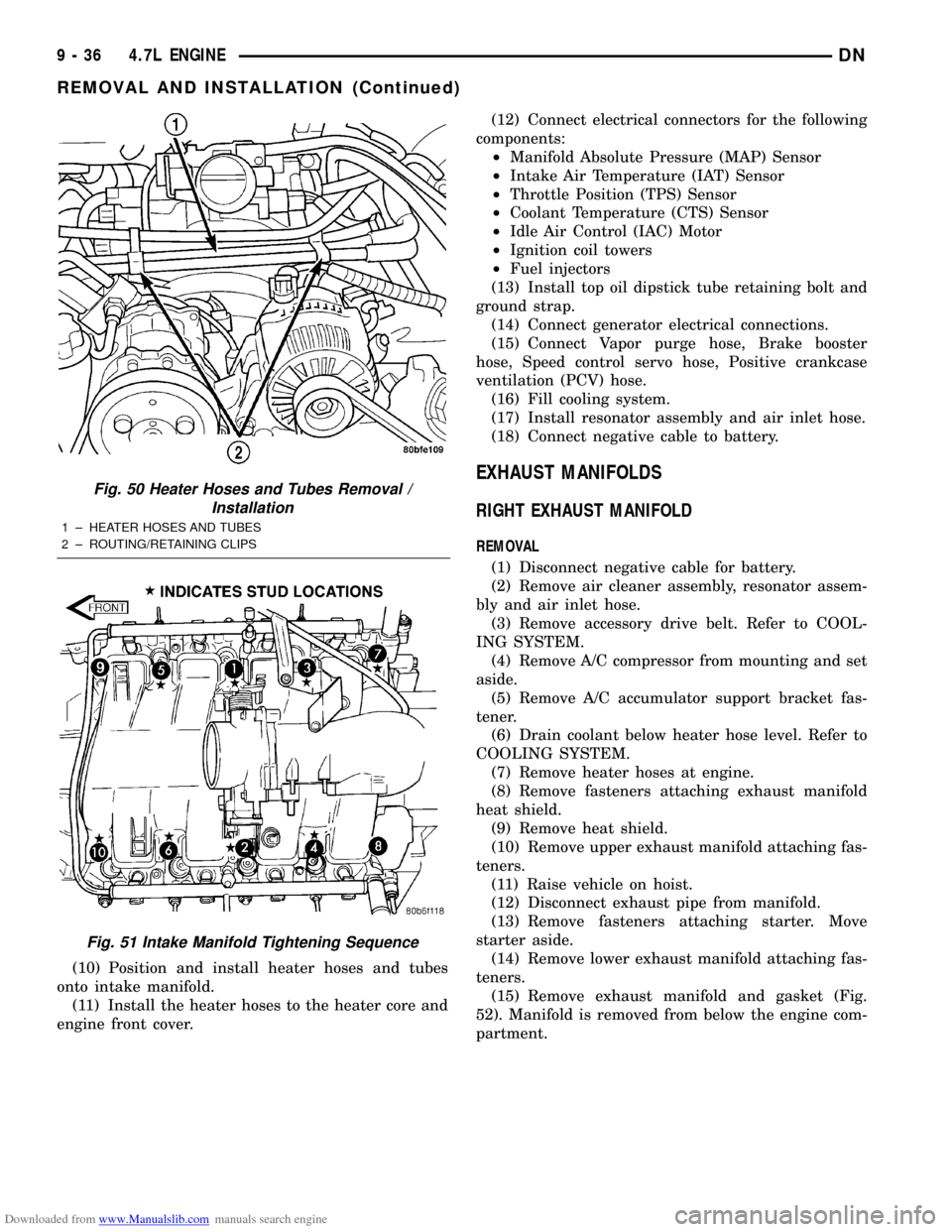
from intake manifold (Fig. 50).
(17) Remove coolant temperature sensor. Refer to
FUEL SYSTEM.
(18) Remove intake manifold retaining fasteners in
reverse order of tightening sequence (Fig. 51).
(19) Remove intake manifold.
INSTALLATION
(1) Install intake manifold gaskets.
(2) Install intake manifold.
(3) Install intake manifold retaining bolts and
tighten in sequence shown in (Fig. 51) to 12 N´m
(105 in. lbs.).
(4) Install left and right radio suppressor straps.
(5) Install throttle body assembly.
(6) Install throttle cable bracket.
(7) Connect throttle cable and speed control cable
to throttle body.
(8) Install fuel rail.
(9) Install ignition coil towers.
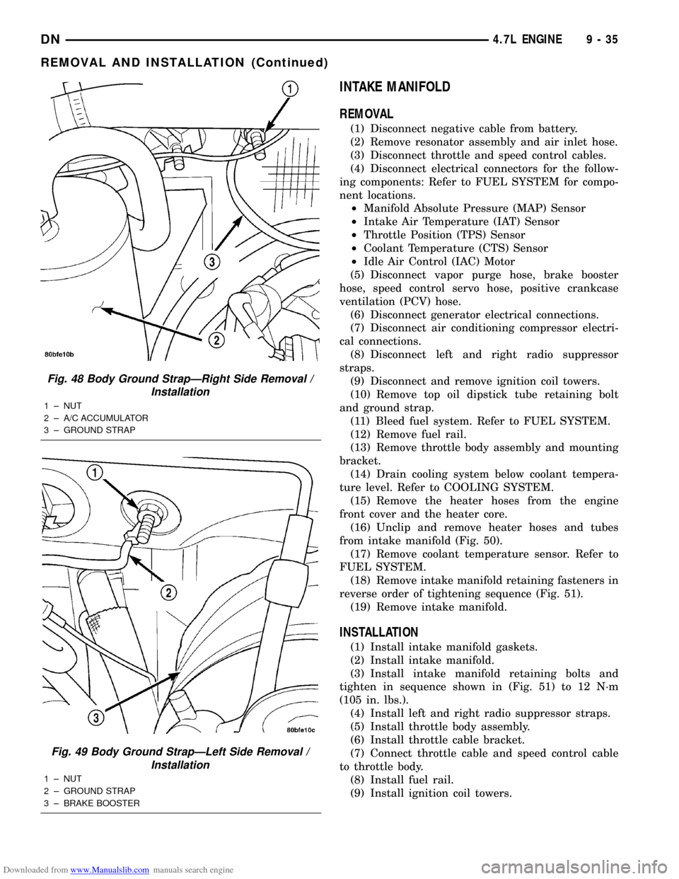
Fig. 48 Body Ground StrapÐRight Side Removal /
Installation
1 ± NUT
2 ± A/C ACCUMULATOR
3 ± GROUND STRAP
Fig. 49 Body Ground StrapÐLeft Side Removal /
Installation
1 ± NUT
2 ± GROUND STRAP
3 ± BRAKE BOOSTER
DN4.7L ENGINE 9 - 35
REMOVAL AND INSTALLATION (Continued)
Page 36 of 193
Downloaded from www.Manualslib.com manuals search engine (10) Position and install heater hoses and tubes
onto intake manifold.
(11) Install the heater hoses to the heater core and
engine front cover.(12) Connect electrical connectors for the following
components:
²Manifold Absolute Pressure (MAP) Sensor
²Intake Air Temperature (IAT) Sensor
²Throttle Position (TPS) Sensor
²Coolant Temperature (CTS) Sensor
²Idle Air Control (IAC) Motor
²Ignition coil towers
²Fuel injectors
(13) Install top oil dipstick tube retaining bolt and
ground strap.
(14) Connect generator electrical connections.
(15) Connect Vapor purge hose, Brake booster
hose, Speed control servo hose, Positive crankcase
ventilation (PCV) hose.
(16) Fill cooling system.
(17) Install resonator assembly and air inlet hose.
(18) Connect negative cable to battery.
EXHAUST MANIFOLDS
RIGHT EXHAUST MANIFOLD
REMOVAL
(1) Disconnect negative cable for battery.
(2) Remove air cleaner assembly, resonator assem-
bly and air inlet hose.
(3) Remove accessory drive belt. Refer to COOL-
ING SYSTEM.
(4) Remove A/C compressor from mounting and set
aside.
(5) Remove A/C accumulator support bracket fas-
tener.
(6) Drain coolant below heater hose level. Refer to
COOLING SYSTEM.
(7) Remove heater hoses at engine.
(8) Remove fasteners attaching exhaust manifold
heat shield.
(9) Remove heat shield.
(10) Remove upper exhaust manifold attaching fas-
teners.
(11) Raise vehicle on hoist.
(12) Disconnect exhaust pipe from manifold.
(13) Remove fasteners attaching starter. Move
starter aside.
(14) Remove lower exhaust manifold attaching fas-
teners.
(15) Remove exhaust manifold and gasket (Fig.
52). Manifold is removed from below the engine com-
partment.
Fig. 50 Heater Hoses and Tubes Removal /
Installation
1 ± HEATER HOSES AND TUBES
2 ± ROUTING/RETAINING CLIPS
Fig. 51 Intake Manifold Tightening Sequence
9 - 36 4.7L ENGINEDN
REMOVAL AND INSTALLATION (Continued)
Page 38 of 193
Downloaded from www.Manualslib.com manuals search engine (9) Install A/C compressor and fasteners.
(10) Install accessory drive belt.
(11) Install air cleaner assembly, resonator assem-
bly and air inlet hose.
(12) Install battery and connect cables.
(13) Fill cooling system.
LEFT EXHAUST MANIFOLD
REMOVAL
(1) Disconnect negative cable for battery.
(2) Hoist vehicle.
(3) Disconnect exhaust pipe at manifold.
(4) Lower vehicle.
(5) Remove the front two exhaust heat shield
retaining fasteners. Raise vehicle and remove the
fasteners at rear of heat shield.
(6) Remove heat shield (Fig. 53).
(7) Lower vehicle and remove the upper exhaust
manifold retaining bolts (Fig. 53).
(8) Raise vehicle and remove the lower exhaust
manifold retaining bolts (Fig. 53).
(9) Remove exhaust manifold and gasket (Fig. 53).
Manifold is removed from below the engine compart-
ment.
INSTALLATION
(1) Install exhaust manifold and gasket from below
engine compartment.
(2) Install lower exhaust manifold fasteners (Fig.
53). DO NOT tighten until all fasteners are in place.
(3) Lower vehicle and install upper exhaust mani-
fold fasteners (Fig. 53). Tighten all manifold bolts
starting at center and working outward to 25 N´m
(18 ft. lbs.).
CAUTION: Over tightening heat shield fasteners,
may cause shield to distort and/or crack.
(4) Install exhaust manifold heat shield (Fig. 53).
Tighten fasteners to 8 N´m (72 in. lbs.), then loosen
45 degrees.
(5) Connect exhaust pipe to manifold.
(6) Connect negative cable to battery.
CYLINDER HEAD COVER
REMOVAL
LEFT SIDE COVER
(1) Disconnect negative cable from battery.
(2) Remove the resonator assemble and air inlet
hose.
(3) Disconnect injector connectors and un-clip the
injector harness.
(4) Route injector harness in front of cylinder head
cover.(5) Disconnect the left side breather tube and
remove the breather tube.
(6) Remove the cylinder head cover mounting
bolts.
(7) Remove cylinder head cover and gasket.
NOTE: The gasket may be used again, provided no
cuts, tears, or deformation has occurred.
INSTALLATION
CAUTION: Do not use harsh cleaners to clean the
cylinder head covers. Severe damage to covers
may occur.
CAUTION: DO NOT allow other components includ-
ing the wire harness to rest on or against the cylin-
der head cover. Prolonged contact with other
objects may wear a hole in the engine cylinder head
cover.
(1) Clean cylinder head cover and both sealing sur-
faces. Inspect and replace gasket as necessary.
(2) Install cylinder head cover and hand start all
fasteners. Verify that all studs are in the correct loca-
tion shown in (Fig. 54).
(3) Tighten cylinder head cover bolts and double
ended studs to 12 N´m (105 in. lbs.).
(4) Install left side breather and connect breather
tube.
(5) Connect injector electrical connectors and injec-
tor harness retaining clips.
(6) Install the resonator and air inlet hose.
(7) Connect negative cable to battery.
REMOVAL
RIGHT SIDE COVER
(1) Disconnect battery negative cable.
(2) Remove air cleaner assembly, resonator assem-
bly and air inlet hose.
(3) Drain cooling system, below the level of the
heater hoses. Refer to COOLING SYSTEM.
(4) Remove accessory drive belt.
(5) Remove air conditioning compressor retaining
bolts and move compressor to the left.
(6) Remove heater hoses.
(7) Disconnect injector and ignition coil connectors.
(8) Disconnect and remove positive crankcase ven-
tilation (PCV) hose.
(9) Remove oil fill tube.
(10) Un-clip injector and ignition coil harness and
move away from cylinder head cover.
(11) Remove right rear breather tube and filter
assembly.
9 - 38 4.7L ENGINEDN
REMOVAL AND INSTALLATION (Continued)
Page 40 of 193
Downloaded from www.Manualslib.com manuals search engine CAUTION: DO NOT allow other components includ-
ing the wire harness to rest on or against the
engine cylinder head cover. Prolonged contact with
other objects may wear a hole in the cylinder head
cover.
(1) Clean cylinder head cover and both sealing sur-
faces. Inspect and replace gasket as necessary.
(2) Install cylinder head cover and hand start all
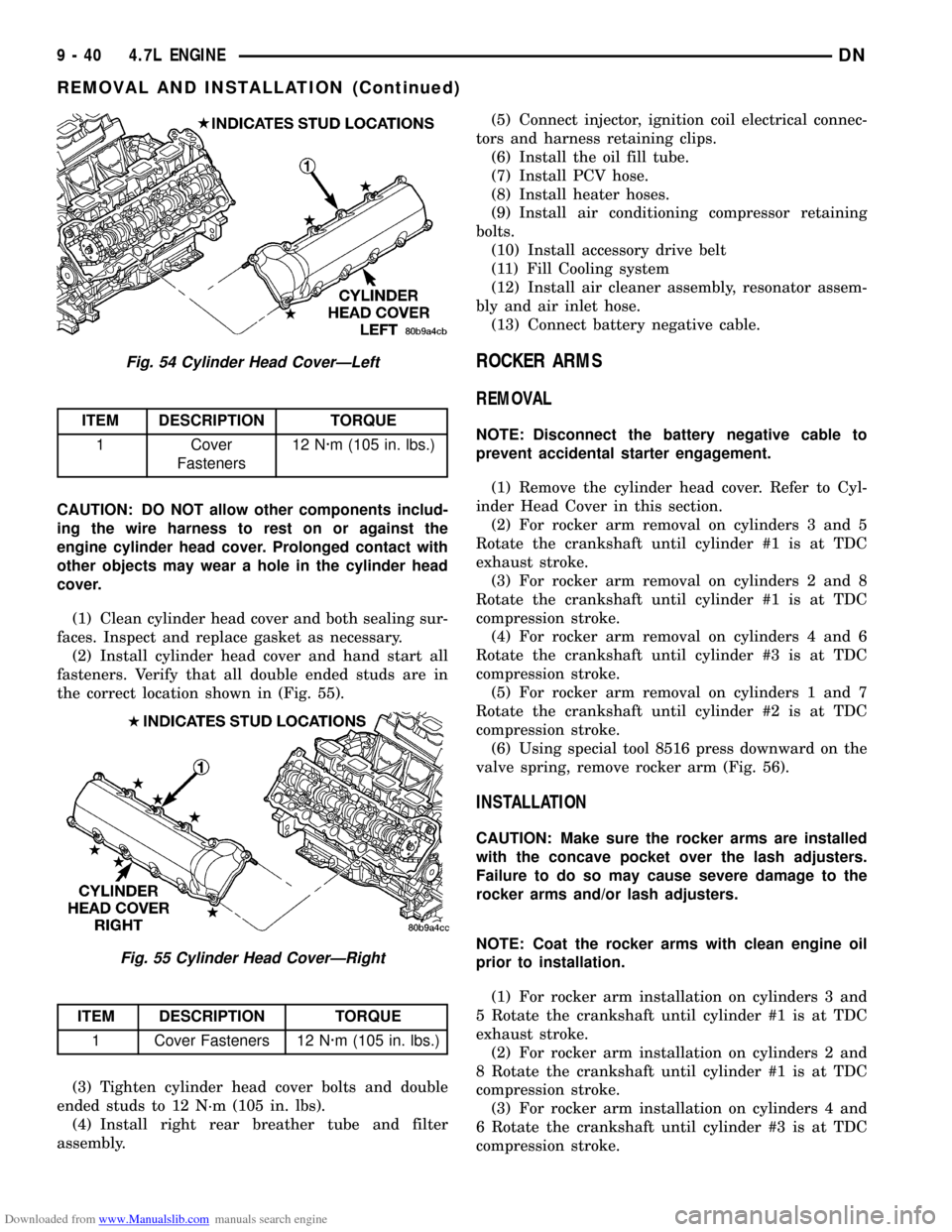
fasteners. Verify that all double ended studs are in
the correct location shown in (Fig. 55).
(3) Tighten cylinder head cover bolts and double
ended studs to 12 N´m (105 in. lbs).
(4) Install right rear breather tube and filter
assembly.(5) Connect injector, ignition coil electrical connec-
tors and harness retaining clips.
(6) Install the oil fill tube.
(7) Install PCV hose.
(8) Install heater hoses.
(9) Install air conditioning compressor retaining
bolts.
(10) Install accessory drive belt
(11) Fill Cooling system
(12) Install air cleaner assembly, resonator assem-
bly and air inlet hose.
(13) Connect battery negative cable.
ROCKER ARMS
REMOVAL
NOTE: Disconnect the battery negative cable to
prevent accidental starter engagement.
(1) Remove the cylinder head cover. Refer to Cyl-
inder Head Cover in this section.
(2) For rocker arm removal on cylinders 3 and 5
Rotate the crankshaft until cylinder #1 is at TDC
exhaust stroke.
(3) For rocker arm removal on cylinders 2 and 8
Rotate the crankshaft until cylinder #1 is at TDC
compression stroke.
(4) For rocker arm removal on cylinders 4 and 6
Rotate the crankshaft until cylinder #3 is at TDC
compression stroke.
(5) For rocker arm removal on cylinders 1 and 7
Rotate the crankshaft until cylinder #2 is at TDC
compression stroke.
(6) Using special tool 8516 press downward on the
valve spring, remove rocker arm (Fig. 56).
INSTALLATION
CAUTION: Make sure the rocker arms are installed
with the concave pocket over the lash adjusters.
Failure to do so may cause severe damage to the
rocker arms and/or lash adjusters.
NOTE: Coat the rocker arms with clean engine oil
prior to installation.
(1) For rocker arm installation on cylinders 3 and
5 Rotate the crankshaft until cylinder #1 is at TDC
exhaust stroke.
(2) For rocker arm installation on cylinders 2 and
8 Rotate the crankshaft until cylinder #1 is at TDC
compression stroke.
(3) For rocker arm installation on cylinders 4 and
6 Rotate the crankshaft until cylinder #3 is at TDC
compression stroke.
Fig. 54 Cylinder Head CoverÐLeft
ITEM DESCRIPTION TORQUE
1 Cover
Fasteners12 N´m (105 in. lbs.)
Fig. 55 Cylinder Head CoverÐRight
ITEM DESCRIPTION TORQUE
1 Cover Fasteners 12 N´m (105 in. lbs.)
9 - 40 4.7L ENGINEDN
REMOVAL AND INSTALLATION (Continued)
Page 108 of 193
Downloaded from www.Manualslib.com manuals search engine (15) Remove intake manifold and throttle body as
an assembly. Discard the flange side gaskets and the
front and rear cross-over gaskets.
(16) Remove exhaust manifolds.
(17) Remove rocker arm assemblies and push rods.
Identify to ensure installation in original locations.
(18) Remove the head bolts from each cylinder
head and remove cylinder heads. Discard the cylin-
der head gasket.
(19) Remove spark plugs.
INSTALLATION
(1) Position the new cylinder head gaskets onto
the cylinder block.
(2) Position the cylinder heads onto head gaskets
and cylinder block.
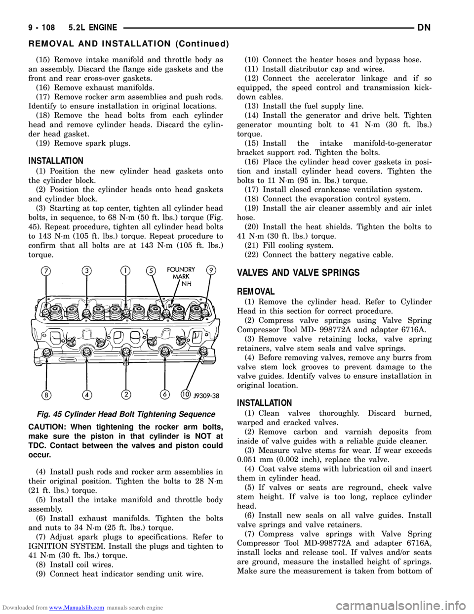
(3) Starting at top center, tighten all cylinder head
bolts, in sequence, to 68 N´m (50 ft. lbs.) torque (Fig.
45). Repeat procedure, tighten all cylinder head bolts
to 143 N´m (105 ft. lbs.) torque. Repeat procedure to
confirm that all bolts are at 143 N´m (105 ft. lbs.)
torque.
CAUTION: When tightening the rocker arm bolts,
make sure the piston in that cylinder is NOT at
TDC. Contact between the valves and piston could
occur.
(4) Install push rods and rocker arm assemblies in
their original position. Tighten the bolts to 28 N´m
(21 ft. lbs.) torque.
(5) Install the intake manifold and throttle body
assembly.
(6) Install exhaust manifolds. Tighten the bolts
and nuts to 34 N´m (25 ft. lbs.) torque.
(7) Adjust spark plugs to specifications. Refer to
IGNITION SYSTEM. Install the plugs and tighten to
41 N´m (30 ft. lbs.) torque.
(8) Install coil wires.
(9) Connect heat indicator sending unit wire.(10) Connect the heater hoses and bypass hose.
(11) Install distributor cap and wires.
(12) Connect the accelerator linkage and if so
equipped, the speed control and transmission kick-
down cables.
(13) Install the fuel supply line.
(14) Install the generator and drive belt. Tighten
generator mounting bolt to 41 N´m (30 ft. lbs.)
torque.
(15) Install the intake manifold-to-generator
bracket support rod. Tighten the bolts.
(16) Place the cylinder head cover gaskets in posi-
tion and install cylinder head covers. Tighten the
bolts to 11 N´m (95 in. lbs.) torque.
(17) Install closed crankcase ventilation system.
(18) Connect the evaporation control system.
(19) Install the air cleaner assembly and air inlet
hose.
(20) Install the heat shields. Tighten the bolts to
41 N´m (30 ft. lbs.) torque.
(21) Fill cooling system.
(22) Connect the battery negative cable.
VALVES AND VALVE SPRINGS
REMOVAL
(1) Remove the cylinder head. Refer to Cylinder
Head in this section for correct procedure.
(2) Compress valve springs using Valve Spring
Compressor Tool MD- 998772A and adapter 6716A.
(3) Remove valve retaining locks, valve spring
retainers, valve stem seals and valve springs.
(4) Before removing valves, remove any burrs from
valve stem lock grooves to prevent damage to the
valve guides. Identify valves to ensure installation in
original location.
INSTALLATION
(1) Clean valves thoroughly. Discard burned,
warped and cracked valves.
(2) Remove carbon and varnish deposits from
inside of valve guides with a reliable guide cleaner.
(3) Measure valve stems for wear. If wear exceeds
0.051 mm (0.002 inch), replace the valve.
(4) Coat valve stems with lubrication oil and insert
them in cylinder head.
(5) If valves or seats are reground, check valve
stem height. If valve is too long, replace cylinder
head.
(6) Install new seals on all valve guides. Install
valve springs and valve retainers.
(7) Compress valve springs with Valve Spring
Compressor Tool MD-998772A and adapter 6716A,
install locks and release tool. If valves and/or seats
are ground, measure the installed height of springs.
Make sure the measurement is taken from bottom ofFig. 45 Cylinder Head Bolt Tightening Sequence
9 - 108 5.2L ENGINEDN
REMOVAL AND INSTALLATION (Continued)
Page 114 of 193
Downloaded from www.Manualslib.com manuals search engine INSTALLATION
Only one main bearing should be selectively fitted
while all other main bearing caps are properly tight-
ened. All bearing capbolts removed during service pro-
cedures are to be cleaned and oiled before installation.
When installing a new upper bearing shell, slightly
chamfer the sharp edges from the plain side.
(1) Start bearing in place, and insert Crankshaft
Main Bearing Remover/Installer Tool C-3059 into oil
hole of crankshaft (Fig. 58).
(2) Slowly rotate crankshaft counterclockwise slid-
ing the bearing into position. Remove Tool C-3059.
(3)
Install the bearing caps. Clean and oil the bolts.
Tighten the capbolts to 115 N´m (85 ft. lbs.) torque.
(4) Install the oil pump.
(5) Install the oil pan.
(6) Start engine check for leaks.
DISTRIBUTOR DRIVE SHAFT BUSHING
REMOVAL
(1) Remove distributor, refer to Group 8D, Ignition
Systems for the proper procedure.
(2) Remove the intake manifold. Refer to Intake
Manifold in this section for correct procedure.
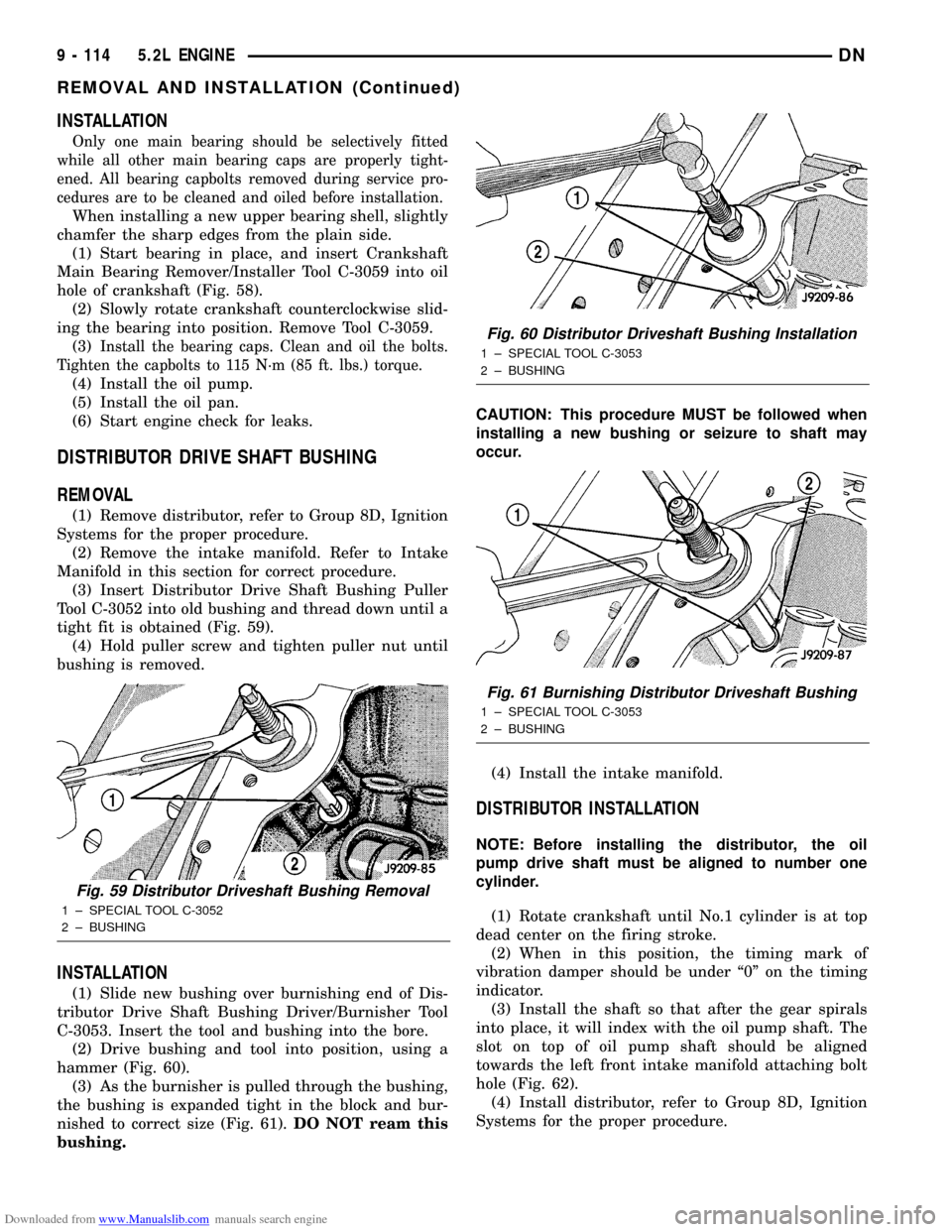
(3) Insert Distributor Drive Shaft Bushing Puller
Tool C-3052 into old bushing and thread down until a
tight fit is obtained (Fig. 59).
(4) Hold puller screw and tighten puller nut until
bushing is removed.
INSTALLATION
(1) Slide new bushing over burnishing end of Dis-
tributor Drive Shaft Bushing Driver/Burnisher Tool
C-3053. Insert the tool and bushing into the bore.
(2) Drive bushing and tool into position, using a
hammer (Fig. 60).
(3) As the burnisher is pulled through the bushing,
the bushing is expanded tight in the block and bur-
nished to correct size (Fig. 61).DO NOT ream this
bushing.CAUTION: This procedure MUST be followed when
installing a new bushing or seizure to shaft may
occur.
(4) Install the intake manifold.
DISTRIBUTOR INSTALLATION
NOTE: Before installing the distributor, the oil
pump drive shaft must be aligned to number one
cylinder.
(1) Rotate crankshaft until No.1 cylinder is at top
dead center on the firing stroke.
(2) When in this position, the timing mark of
vibration damper should be under ª0º on the timing
indicator.
(3) Install the shaft so that after the gear spirals
into place, it will index with the oil pump shaft. The
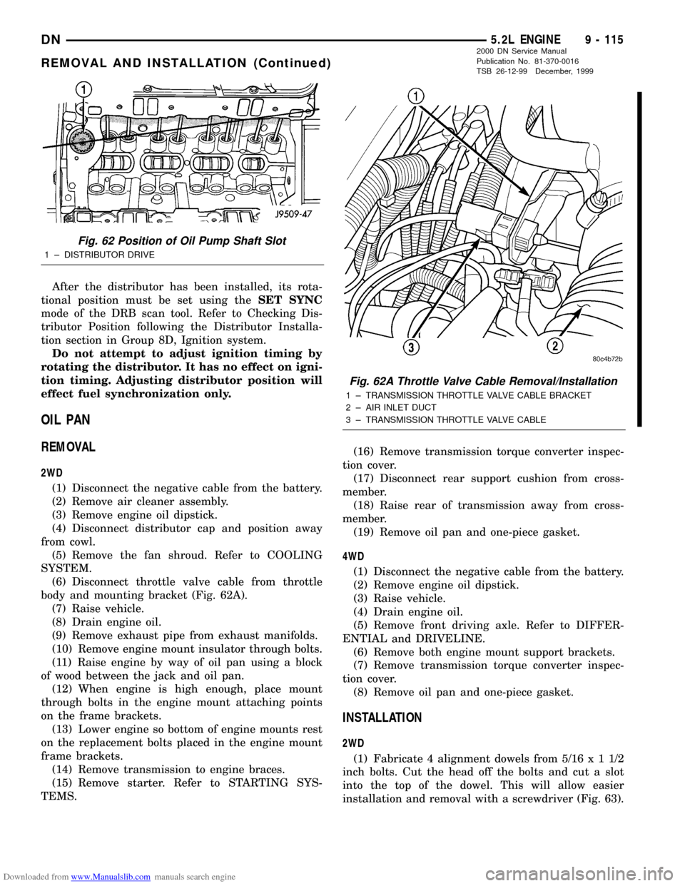
slot on top of oil pump shaft should be aligned
towards the left front intake manifold attaching bolt
hole (Fig. 62).
(4) Install distributor, refer to Group 8D, Ignition
Systems for the proper procedure.
Fig. 59 Distributor Driveshaft Bushing Removal
1 ± SPECIAL TOOL C-3052
2 ± BUSHING
Fig. 60 Distributor Driveshaft Bushing Installation
1 ± SPECIAL TOOL C-3053
2 ± BUSHING
Fig. 61 Burnishing Distributor Driveshaft Bushing
1 ± SPECIAL TOOL C-3053
2 ± BUSHING
9 - 114 5.2L ENGINEDN
REMOVAL AND INSTALLATION (Continued)
Page 115 of 193
Downloaded from www.Manualslib.com manuals search engine After the distributor has been installed, its rota-
tional position must be set using theSET SYNC
mode of the DRB scan tool. Refer to Checking Dis-
tributor Position following the Distributor Installa-
tion section in Group 8D, Ignition system.
Do not attempt to adjust ignition timing by
rotating the distributor. It has no effect on igni-
tion timing. Adjusting distributor position will
effect fuel synchronization only.
OIL PAN
REMOVAL
2WD
(1) Disconnect the negative cable from the battery.
(2) Remove air cleaner assembly.
(3) Remove engine oil dipstick.
(4) Disconnect distributor cap and position away
from cowl.
(5) Remove the fan shroud. Refer to COOLING
SYSTEM.
(6) Disconnect throttle valve cable from throttle
body and mounting bracket (Fig. 62A).
(7) Raise vehicle.
(8) Drain engine oil.
(9) Remove exhaust pipe from exhaust manifolds.
(10) Remove engine mount insulator through bolts.
(11) Raise engine by way of oil pan using a block
of wood between the jack and oil pan.
(12) When engine is high enough, place mount
through bolts in the engine mount attaching points
on the frame brackets.
(13) Lower engine so bottom of engine mounts rest
on the replacement bolts placed in the engine mount
frame brackets.
(14) Remove transmission to engine braces.
(15) Remove starter. Refer to STARTING SYS-
TEMS.(16) Remove transmission torque converter inspec-
tion cover.
(17) Disconnect rear support cushion from cross-
member.
(18) Raise rear of transmission away from cross-
member.
(19) Remove oil pan and one-piece gasket.
4WD
(1) Disconnect the negative cable from the battery.
(2) Remove engine oil dipstick.
(3) Raise vehicle.
(4) Drain engine oil.
(5) Remove front driving axle. Refer to DIFFER-
ENTIAL and DRIVELINE.
(6) Remove both engine mount support brackets.
(7) Remove transmission torque converter inspec-
tion cover.
(8) Remove oil pan and one-piece gasket.
INSTALLATION
2WD
(1) Fabricate 4 alignment dowels from 5/16x11/2
inch bolts. Cut the head off the bolts and cut a slot
into the top of the dowel. This will allow easier
installation and removal with a screwdriver (Fig. 63).
Fig. 62 Position of Oil Pump Shaft Slot
1 ± DISTRIBUTOR DRIVE
Fig. 62A Throttle Valve Cable Removal/Installation
1 ± TRANSMISSION THROTTLE VALVE CABLE BRACKET
2 ± AIR INLET DUCT
3 ± TRANSMISSION THROTTLE VALVE CABLE
DN5.2L ENGINE 9 - 115
REMOVAL AND INSTALLATION (Continued)
2000 DN Service Manual
Publication No. 81-370-0016
TSB 26-12-99 December, 1999