Mode DODGE DURANGO 1999 1.G Workshop Manual
[x] Cancel search | Manufacturer: DODGE, Model Year: 1999, Model line: DURANGO, Model: DODGE DURANGO 1999 1.GPages: 193, PDF Size: 5.65 MB
Page 115 of 193

Downloaded from www.Manualslib.com manuals search engine After the distributor has been installed, its rota-
tional position must be set using theSET SYNC
mode of the DRB scan tool. Refer to Checking Dis-
tributor Position following the Distributor Installa-
tion section in Group 8D, Ignition system.
Do not attempt to adjust ignition timing by
rotating the distributor. It has no effect on igni-
tion timing. Adjusting distributor position will
effect fuel synchronization only.
OIL PAN
REMOVAL
2WD
(1) Disconnect the negative cable from the battery.
(2) Remove air cleaner assembly.
(3) Remove engine oil dipstick.
(4) Disconnect distributor cap and position away
from cowl.
(5) Remove the fan shroud. Refer to COOLING
SYSTEM.
(6) Disconnect throttle valve cable from throttle
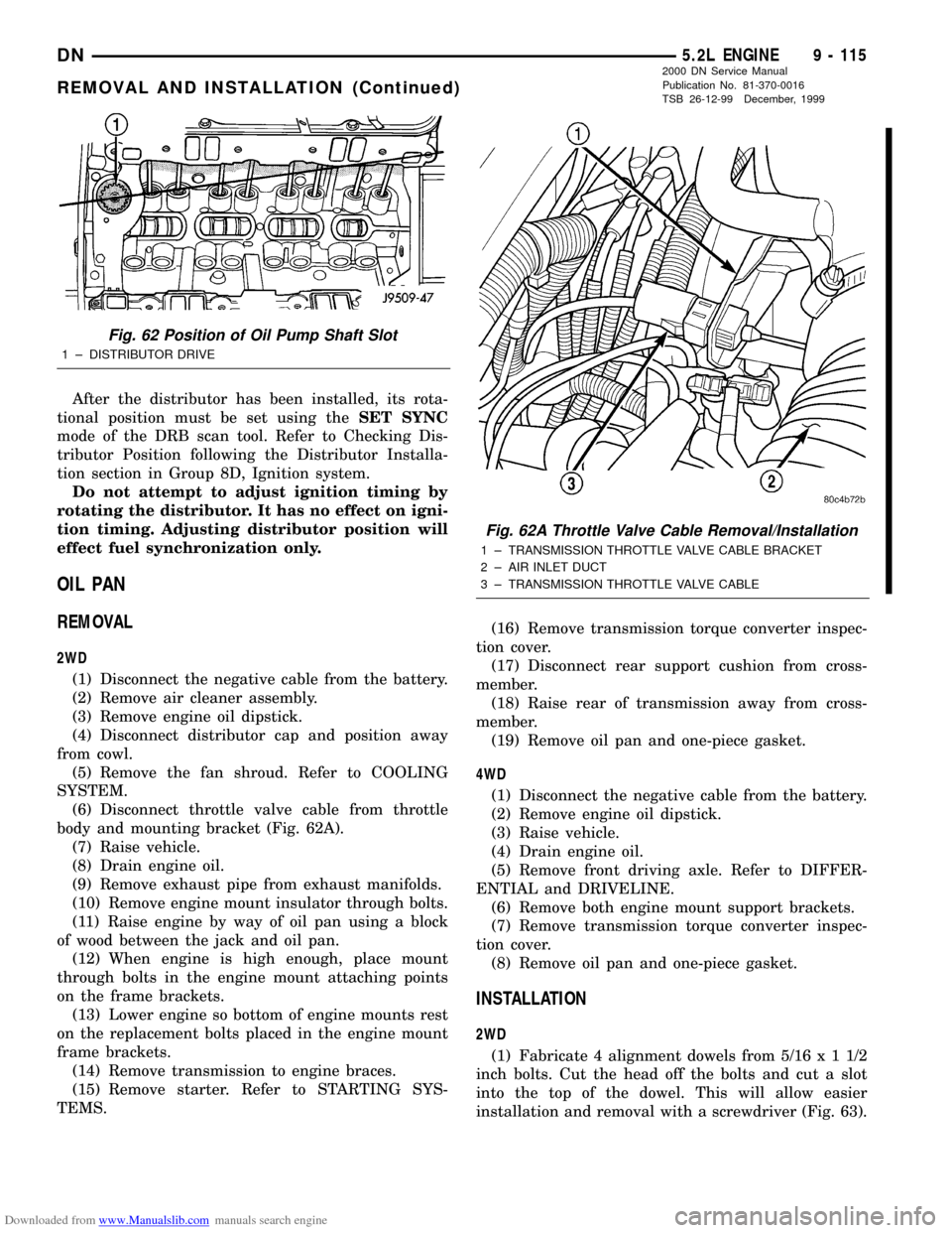
body and mounting bracket (Fig. 62A).
(7) Raise vehicle.
(8) Drain engine oil.
(9) Remove exhaust pipe from exhaust manifolds.
(10) Remove engine mount insulator through bolts.
(11) Raise engine by way of oil pan using a block
of wood between the jack and oil pan.
(12) When engine is high enough, place mount
through bolts in the engine mount attaching points
on the frame brackets.
(13) Lower engine so bottom of engine mounts rest
on the replacement bolts placed in the engine mount
frame brackets.
(14) Remove transmission to engine braces.
(15) Remove starter. Refer to STARTING SYS-
TEMS.(16) Remove transmission torque converter inspec-
tion cover.
(17) Disconnect rear support cushion from cross-
member.
(18) Raise rear of transmission away from cross-
member.
(19) Remove oil pan and one-piece gasket.
4WD
(1) Disconnect the negative cable from the battery.
(2) Remove engine oil dipstick.
(3) Raise vehicle.
(4) Drain engine oil.
(5) Remove front driving axle. Refer to DIFFER-
ENTIAL and DRIVELINE.
(6) Remove both engine mount support brackets.
(7) Remove transmission torque converter inspec-
tion cover.
(8) Remove oil pan and one-piece gasket.
INSTALLATION
2WD
(1) Fabricate 4 alignment dowels from 5/16x11/2
inch bolts. Cut the head off the bolts and cut a slot
into the top of the dowel. This will allow easier
installation and removal with a screwdriver (Fig. 63).
Fig. 62 Position of Oil Pump Shaft Slot
1 ± DISTRIBUTOR DRIVE
Fig. 62A Throttle Valve Cable Removal/Installation
1 ± TRANSMISSION THROTTLE VALVE CABLE BRACKET
2 ± AIR INLET DUCT
3 ± TRANSMISSION THROTTLE VALVE CABLE
DN5.2L ENGINE 9 - 115
REMOVAL AND INSTALLATION (Continued)
2000 DN Service Manual
Publication No. 81-370-0016
TSB 26-12-99 December, 1999
Page 174 of 193

Downloaded from www.Manualslib.com manuals search engine (4) Hold puller screw and tighten puller nut until
bushing is removed.
INSTALLATION
(1) Slide new bushing over burnishing end of Dis-
tributor Drive Shaft Bushing Driver/Burnisher Tool
C-3053. Insert the tool and bushing into the bore.
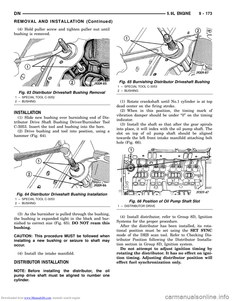
(2) Drive bushing and tool into position, using a
hammer (Fig. 64).
(3) As the burnisher is pulled through the bushing,
the bushing is expanded tight in the block and bur-
nished to correct size (Fig. 65).DO NOT ream this
bushing.
CAUTION: This procedure MUST be followed when
installing a new bushing or seizure to shaft may
occur.
(4) Install the intake manifold.
DISTRIBUTOR INSTALLATION
NOTE: Before installing the distributor, the oil
pump drive shaft must be aligned to number one
cylinder.(1) Rotate crankshaft until No.1 cylinder is at top
dead center on the firing stroke.
(2) When in this position, the timing mark of
vibration damper should be under ª0º on the timing
indicator.
(3) Install the shaft so that after the gear spirals
into place, it will index with the oil pump shaft. The
slot on top of oil pump shaft should be aligned
towards the left front intake manifold attaching bolt
hole (Fig. 66).
(4) Install distributor, refer to Group 8D, Ignition
Systems for the proper procedure.
After the distributor has been installed, its rota-
tional position must be set using theSET SYNC
mode of the DRB scan tool. Refer to Checking Dis-
tributor Position following the Distributor Installa-
tion section in Group 8D, Ignition system.
Do not attempt to adjust ignition timing by
rotating the distributor. It has no effect on igni-
tion timing. Adjusting distributor position will
effect fuel synchronization only.
Fig. 63 Distributor Driveshaft Bushing Removal
1 ± SPECIAL TOOL C-3052
2 ± BUSHING
Fig. 64 Distributor Driveshaft Bushing Installation
1 ± SPECIAL TOOL C-3053
2 ± BUSHING
Fig. 65 Burnishing Distributor Driveshaft Bushing
1 ± SPECIAL TOOL C-3053
2 ± BUSHING
Fig. 66 Position of Oil Pump Shaft Slot
1 ± DISTRIBUTOR DRIVE
DN5.9L ENGINE 9 - 173
REMOVAL AND INSTALLATION (Continued)