cylinder DODGE DURANGO 1999 1.G Workshop Manual
[x] Cancel search | Manufacturer: DODGE, Model Year: 1999, Model line: DURANGO, Model: DODGE DURANGO 1999 1.GPages: 193, PDF Size: 5.65 MB
Page 1 of 193
Downloaded from www.Manualslib.com manuals search engine ENGINE
TABLE OF CONTENTS
page page
4.7L ENGINE.............................. 1
5.2L ENGINE............................. 865.9L ENGINE............................ 135
4.7L ENGINE
TABLE OF CONTENTS
page page
DESCRIPTION AND OPERATION
ENGINE.................................2
ENGINE LUBRICATION SYSTEM..............3
CYLINDER BLOCK.........................5
CRANKSHAFT............................5
PISTON AND CONNECTING ROD.............5
CYLINDER HEAD..........................5
VALVE GUIDES...........................5
VALVES.................................5
VALVE STEM SEAL........................5
VALVE SPRING...........................6
HYDRAULIC LASH ADJUSTER...............6
TIMING DRIVE SYSTEM....................6
CAMSHAFT..............................6
ROCKER ARM............................6
CYLINDER HEAD COVER...................6
OILPAN.................................7
STRUCTURAL DUST COVER................7
INTAKE MANIFOLD........................7
EXHAUST MANIFOLD......................7
DIAGNOSIS AND TESTING
ENGINE DIAGNOSISÐINTRODUCTION.........7
SERVICE DIAGNOSISÐPERFORMANCE.......8
SERVICE DIAGNOSISÐMECHANICAL.........10
SERVICE DIAGNOSISÐLUBRICATION.........11
INTAKE MANIFOLD LEAKAGE DIAGNOSIS.....11
CYLINDER COMPRESSION PRESSURE TEST . . 11
CYLINDER HEAD GASKET FAILURE
DIAGNOSIS...........................12
CYLINDER COMBUSTION PRESSURE
LEAKAGE TEST........................12
ENGINE OIL LEAK INSPECTION.............13
REAR SEAL AREA LEAKSÐINSPECTION......14
HYDRAULIC LASH ADJUSTER NOISE
DIAGNOSIS...........................14
CHECKING ENGINE OIL PRESSURE..........15SERVICE PROCEDURES
FORM-IN-PLACE GASKETS.................15
ENGINE OIL.............................16
REPAIR DAMAGED OR WORN THREADS......17
CYLINDER BOREÐHONING................18
HYDROSTATIC LOCK.....................18
VALVE SERVICE.........................19
ENGINE TIMINGÐVERIFICATION............19
TIMING CHAINÐMEASURING WEAR.........22
PISTONSÐFITTING.......................22
PISTON RINGSÐFITTING..................24
CONNECTING ROD BEARINGSÐFITTING.....25
CRANKSHAFT MAIN BEARINGS.............27
REMOVAL AND INSTALLATION
ENGINE MOUNTSÐLEFT AND RIGHT.........28
ENGINE MOUNTÐREAR...................29
STRUCTURAL COVER.....................30
ENGINE ASSEMBLY.......................31
INTAKE MANIFOLD.......................35
EXHAUST MANIFOLDS....................36
CYLINDER HEAD COVER..................38
ROCKER ARMS..........................40
CYLINDER HEADS........................41
VALVE SPRINGS AND SEALS...............46
HYDRAULIC LASH ADJUSTER..............46
CRANKSHAFT DAMPER...................47
TIMING CHAIN COVER....................48
TIMING CHAIN AND SPROCKETS............49
IDLER SHAFTÐTIMING DRIVE..............55
CAMSHAFTSÐIN VEHICLE.................56
CRANKSHAFT MAIN BEARINGS.............61
OIL PAN 4X2 VEHICLE.....................61
OIL PAN 4X4 VEHICLE.....................64
PISTON AND CONNECTING ROD............65
CRANKSHAFT...........................67
FLEXPLATE.............................69
DNENGINE 9 - 1
Page 2 of 193
Downloaded from www.Manualslib.com manuals search engine OIL PUMP..............................69
ENGINE OIL PRESSURE SENDING UNIT......70
CRANKSHAFT OIL SEALÐFRONT............70
CRANKSHAFT OIL SEALÐREAR.............73
ENGINE CORE PLUGS....................74
DISASSEMBLY AND ASSEMBLY
OIL PUMP..............................74
CLEANING AND INSPECTION
INTAKE MANIFOLD.......................75
EXHAUST MANIFOLD.....................75CYLINDER HEADS........................75
PISTON AND CONNECTING ROD............76
OILPAN................................76
OIL PUMP..............................76
CYLINDER BLOCK........................76
SPECIFICATIONS
4.7L ENGINE............................78
TORQUE...............................81
SPECIAL TOOLS
4.7L ENGINE............................82
DESCRIPTION AND OPERATION
ENGINE
DESCRIPTION
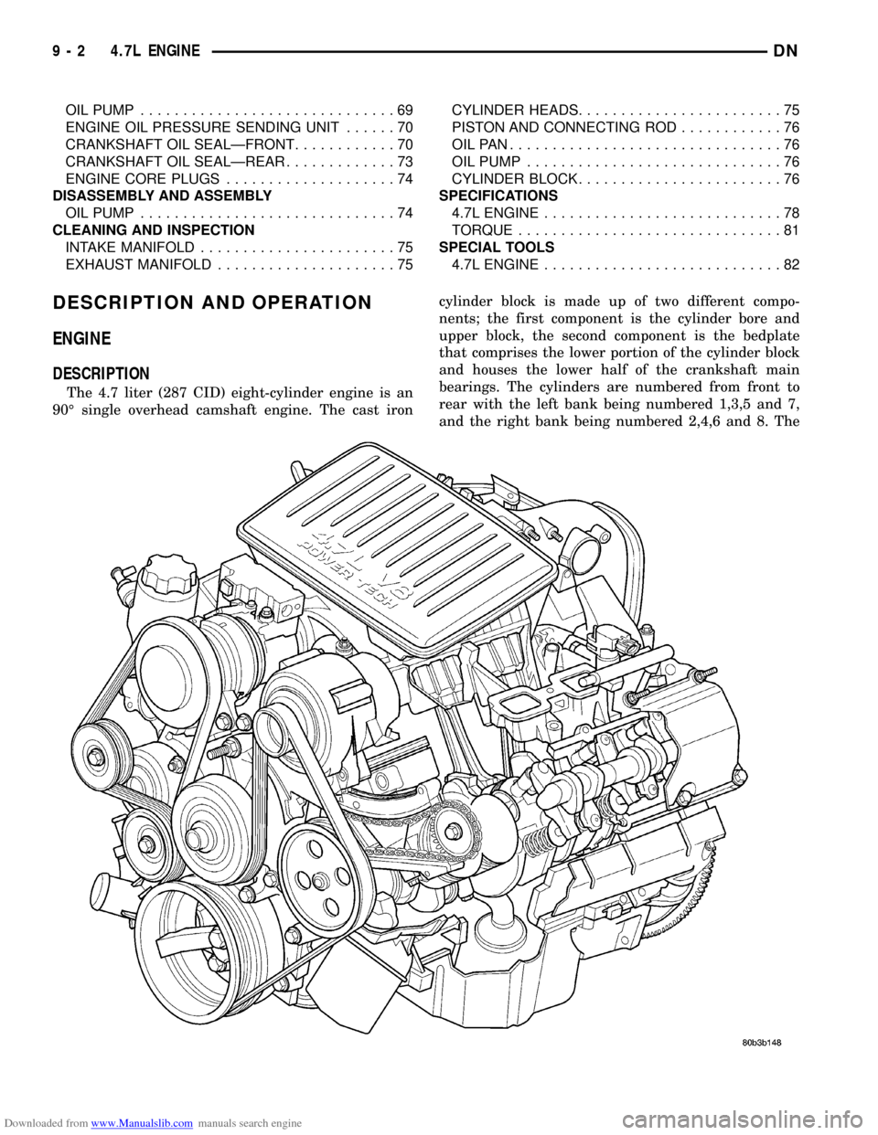
The 4.7 liter (287 CID) eight-cylinder engine is an
90É single overhead camshaft engine. The cast ironcylinder block is made up of two different compo-
nents; the first component is the cylinder bore and
upper block, the second component is the bedplate
that comprises the lower portion of the cylinder block
and houses the lower half of the crankshaft main
bearings. The cylinders are numbered from front to
rear with the left bank being numbered 1,3,5 and 7,
and the right bank being numbered 2,4,6 and 8. The
9 - 2 4.7L ENGINEDN
Page 3 of 193
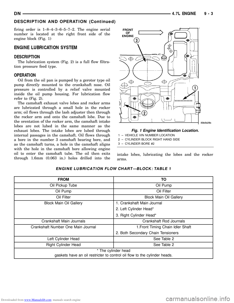
Downloaded from www.Manualslib.com manuals search engine firing order is 1±8±4±3±6±5±7±2. The engine serial
number is located at the right front side of the
engine block (Fig. 1)
ENGINE LUBRICATION SYSTEM
DESCRIPTION
The lubrication system (Fig. 2) is a full flow filtra-
tion pressure feed type.
OPERATION
Oil from the oil pan is pumped by a gerotor type oil
pump directly mounted to the crankshaft nose. Oil
pressure is controlled by a relief valve mounted
inside the oil pump housing. For lubrication flow
refer to (Fig. 2).
The camshaft exhaust valve lobes and rocker arms
are lubricated through a small hole in the rocker
arm; oil flows through the lash adjuster then through
the rocker arm and onto the camshaft lobe. Due to
the orentation of the rocker arm, the camshaft intake
lobes are not lubed in the same manner as the
exhaust lobes. The intake lobes are lubed through
internal passages in the camshaft. Oil flows through
a bore in the number 3 camshaft bearing bore, and
as the camshaft turns, a hole in the camshaft aligns
with the hole in the camshaft bore allowing engine
oil to enter the camshaft tube. The oil then exits
through 1.6mm (0.063 in.) holes drilled into theintake lobes, lubricating the lobes and the rocker
arms.
ENGINE LUBRICATION FLOW CHARTÐBLOCK: TABLE 1
FROM TO
Oil Pickup Tube Oil Pump
Oil Pump Oil Filter
Oil Filter Block Main Oil Gallery
Block Main Oil Gallery 1. Crankshaft Main Journal
2. Left Cylinder Head*
3. Right Cylinder Head*
Crankshaft Main Journals Crankshaft Rod Journals
Crankshaft Number One Main Journal 1.Front Timing Chain Idler Shaft
2. Both Secondary Chain Tensioners
Left Cylinder Head See Table 2
Right Cylinder Head See Table 2
* The cylinder head
gaskets have an oil restricter to control oil flow to the cylinder heads.
Fig. 1 Engine Identification Location.
1 ± VEHICLE VIN NUMBER LOCATION
2 ± CYLINDER BLOCK RIGHT HAND SIDE
3 ± CYLINDER BORE #2
DN4.7L ENGINE 9 - 3
DESCRIPTION AND OPERATION (Continued)
Page 4 of 193
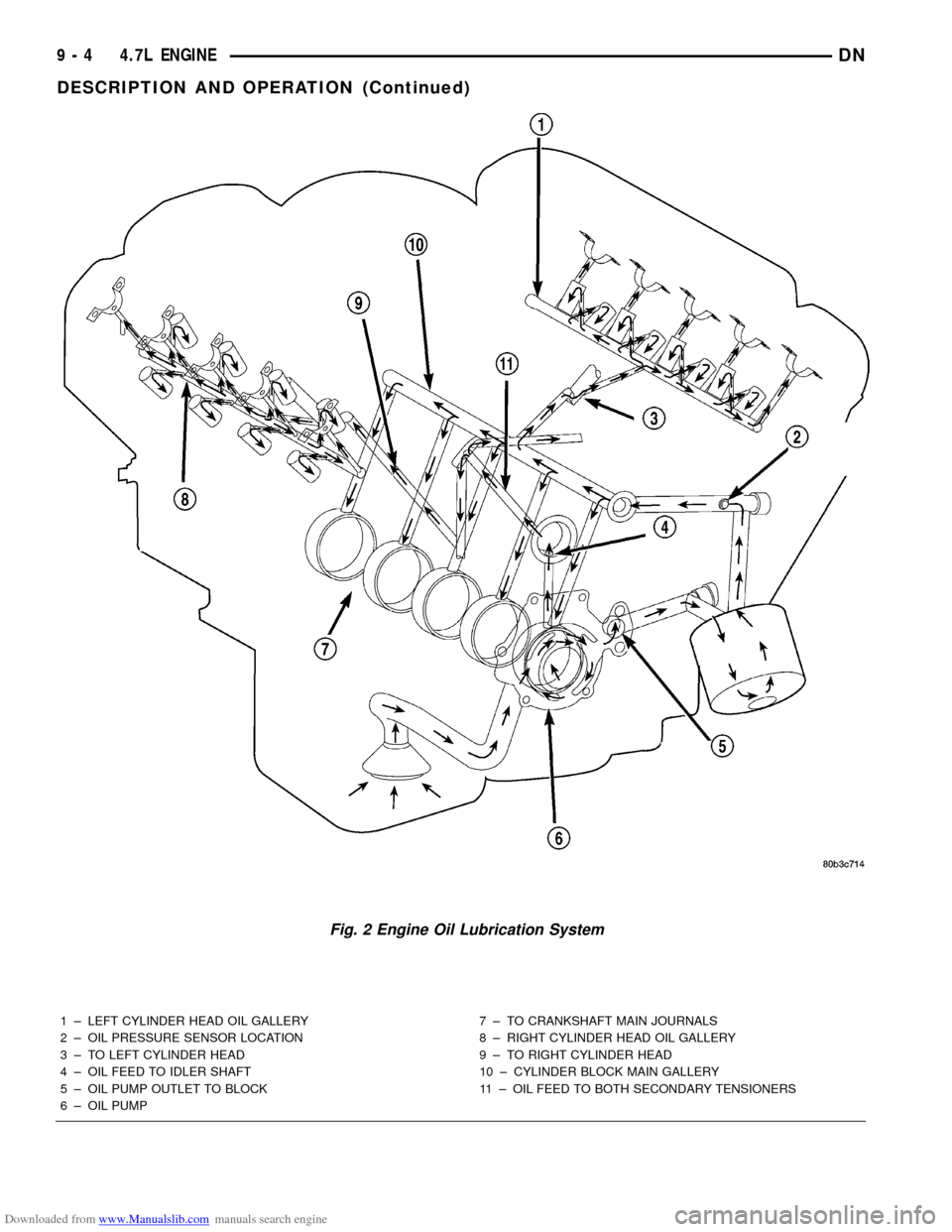
Downloaded from www.Manualslib.com manuals search engine 1 ± LEFT CYLINDER HEAD OIL GALLERY
2 ± OIL PRESSURE SENSOR LOCATION
3 ± TO LEFT CYLINDER HEAD
4 ± OIL FEED TO IDLER SHAFT
5 ± OIL PUMP OUTLET TO BLOCK
6 ± OIL PUMP7 ± TO CRANKSHAFT MAIN JOURNALS
8 ± RIGHT CYLINDER HEAD OIL GALLERY
9 ± TO RIGHT CYLINDER HEAD
10 ± CYLINDER BLOCK MAIN GALLERY
11 ± OIL FEED TO BOTH SECONDARY TENSIONERS
Fig. 2 Engine Oil Lubrication System
9 - 4 4.7L ENGINEDN
DESCRIPTION AND OPERATION (Continued)
Page 5 of 193
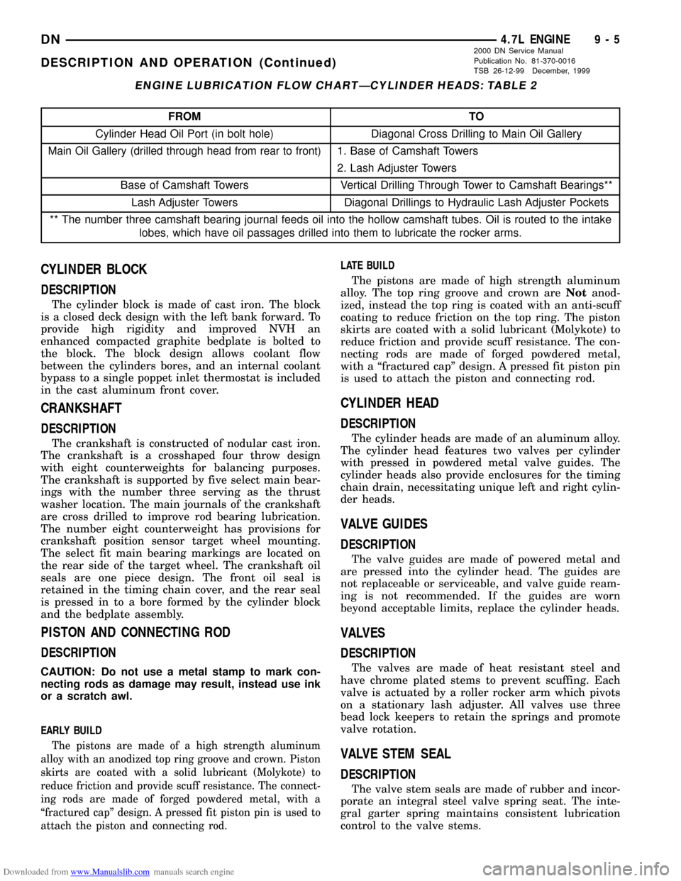
Downloaded from www.Manualslib.com manuals search engine ENGINE LUBRICATION FLOW CHARTÐCYLINDER HEADS: TABLE 2
FROM TO
Cylinder Head Oil Port (in bolt hole) Diagonal Cross Drilling to Main Oil Gallery
Main Oil Gallery (drilled through head from rear to front)1. Base of Camshaft Towers
2. Lash Adjuster Towers
Base of Camshaft Towers Vertical Drilling Through Tower to Camshaft Bearings**
Lash Adjuster Towers Diagonal Drillings to Hydraulic Lash Adjuster Pockets
** The number three camshaft bearing journal feeds oil into the hollow camshaft tubes. Oil is routed to the intake
lobes, which have oil passages drilled into them to lubricate the rocker arms.
CYLINDER BLOCK
DESCRIPTION
The cylinder block is made of cast iron. The block
is a closed deck design with the left bank forward. To
provide high rigidity and improved NVH an
enhanced compacted graphite bedplate is bolted to
the block. The block design allows coolant flow
between the cylinders bores, and an internal coolant
bypass to a single poppet inlet thermostat is included
in the cast aluminum front cover.
CRANKSHAFT
DESCRIPTION
The crankshaft is constructed of nodular cast iron.
The crankshaft is a crosshaped four throw design
with eight counterweights for balancing purposes.
The crankshaft is supported by five select main bear-
ings with the number three serving as the thrust
washer location. The main journals of the crankshaft
are cross drilled to improve rod bearing lubrication.
The number eight counterweight has provisions for
crankshaft position sensor target wheel mounting.
The select fit main bearing markings are located on
the rear side of the target wheel. The crankshaft oil
seals are one piece design. The front oil seal is
retained in the timing chain cover, and the rear seal
is pressed in to a bore formed by the cylinder block
and the bedplate assembly.
PISTON AND CONNECTING ROD
DESCRIPTION
CAUTION: Do not use a metal stamp to mark con-
necting rods as damage may result, instead use ink
or a scratch awl.
EARLY BUILD
The pistons are made of a high strength aluminum
alloy with an anodized top ring groove and crown. Piston
skirts are coated with a solid lubricant (Molykote) to
reduce friction and provide scuff resistance. The connect-
ing rods are made of forged powdered metal, with a
ªfractured capº design. A pressed fit piston pin is used to
attach the piston and connecting rod.
LATE BUILD
The pistons are made of high strength aluminum
alloy. The top ring groove and crown areNotanod-
ized, instead the top ring is coated with an anti-scuff
coating to reduce friction on the top ring. The piston
skirts are coated with a solid lubricant (Molykote) to
reduce friction and provide scuff resistance. The con-
necting rods are made of forged powdered metal,
with a ªfractured capº design. A pressed fit piston pin
is used to attach the piston and connecting rod.
CYLINDER HEAD
DESCRIPTION
The cylinder heads are made of an aluminum alloy.
The cylinder head features two valves per cylinder
with pressed in powdered metal valve guides. The
cylinder heads also provide enclosures for the timing
chain drain, necessitating unique left and right cylin-
der heads.
VALVE GUIDES
DESCRIPTION
The valve guides are made of powered metal and
are pressed into the cylinder head. The guides are
not replaceable or serviceable, and valve guide ream-
ing is not recommended. If the guides are worn
beyond acceptable limits, replace the cylinder heads.
VALVES
DESCRIPTION
The valves are made of heat resistant steel and
have chrome plated stems to prevent scuffing. Each
valve is actuated by a roller rocker arm which pivots
on a stationary lash adjuster. All valves use three
bead lock keepers to retain the springs and promote
valve rotation.
VALVE STEM SEAL
DESCRIPTION
The valve stem seals are made of rubber and incor-
porate an integral steel valve spring seat. The inte-
gral garter spring maintains consistent lubrication
control to the valve stems.
DN4.7L ENGINE 9 - 5
DESCRIPTION AND OPERATION (Continued)
2000 DN Service Manual
Publication No. 81-370-0016
TSB 26-12-99 December, 1999
Page 6 of 193
Downloaded from www.Manualslib.com manuals search engine VALVE SPRING
DESCRIPTION
The valve springs are made from high strength
chrome silicon steel. The springs are common for
intake and exhaust applications. The valve spring
seat is integral with the valve stem seal, which is a
positive type seal to control lubrication.
HYDRAULIC LASH ADJUSTER
DESCRIPTION
Valve lash is controlled by hydraulic lash adjusters
that are stationary mounted in the cylinder heads.
The lash adjusters have a hole in the ball plunger
that feeds oil through the rocker arm squirt holes for
rocker arm roller and camshaft lobe lubrication.
TIMING DRIVE SYSTEM
DESCRIPTION
The timing drive system has been designed to pro-
vide quiet performance and reliability to support a
non-free wheelingengine. Specifically the intake
valves are non-free wheeling and can be easily dam-
aged with forceful engine rotation if camshaft-to-
crankshaft timing is incorrect. The timing drive
system consists of a primary chain and two second-
ary timing chain drives.
OPERATION
The primary timing chain is a single inverted tooth
type. The primary chain drives the large fifty tooth
idler sprocket directly from a 25 tooth crankshaft
sprocket. Primary chain motion is controlled by a
pivoting leaf spring tensioner arm and a fixed guide.
The arm and the guide both use nylon plastic wear
faces for low friction and long wear. The primary
chain receives oil splash lubrication from the second-
ary chain drive and oil pump leakage. The idler
sprocket assembly connects the primary and second-
ary chain drives. The idler sprocket assembly con-
sists of two integral thirty tooth sprockets and a fifty
tooth sprocket that is splined to the assembly. The
spline joint is a non ± serviceable press fit anti rattle
type. A spiral ring is installed on the outboard side of
the fifty tooth sprocket to prevent spline disengage-
ment. The idler sprocket assembly spins on a station-
ary idler shaft. The idler shaft is press-fit into the
cylinder block. A large washer on the idler shaft bolt
and the rear flange of the idler shaft are used to con-
trol sprocket thrust movement. Pressurized oil is
routed through the center of the idler shaft to pro-
vide lubrication for the two bushings used in the
idler sprocket assembly.There are two secondary drive chains, both are
inverted tooth type, one to drive the camshaft in each
SOHC cylinder head. There are no shaft speed
changes in the secondary chain drive system. Each
secondary chain drives a thirty tooth cam sprocket
directly from the thirty tooth sprocket on the idler
sprocket assembly. A fixed chain guide and a hydrau-
lic oil damped tensioner are used to maintain tension
in each secondary chain system. The hydraulic ten-
sioners for the secondary chain systems are fed pres-
surized oil from oil reservoir pockets in the block.
Each tensioner also has a mechanical ratchet system
that limits chain slack if the tensioner piston bleeds
down after engine shut down. The tensioner arms
and guides also utilize nylon wear faces for low fric-
tion and long wear. The secondary timing chains
receive lubrication from a small orifice in the ten-
sioners. This orifice is protected from clogging by a
fine mesh screen which is located on the back of the
hydraulic tensioners.
CAMSHAFT
DESCRIPTION
The camshafts consist of powdered metal steel
lobes which are sinter-bonded to a steel tube. A steel
post or nose piece is friction-welded to the steel cam-
shaft tube. Five bearing journals are machined into
the camshaft, four on the steel tube and one on the
steel nose piece. Camshaft end play is controlled by
two thrust walls that border the nose piece journal.
Engine oil enters the hollow camshafts at the third
journal and lubricates every intake lobe rocker
through a drilled passage in the intake lobe.
ROCKER ARM
DESCRIPTION
The rocker arms are steel stampings with an inte-
gral roller bearing. The rocker arms incorporate a 2.8
mm (0.11 inch) oil hole in the lash adjuster socket for
roller and camshaft lubrication.
CYLINDER HEAD COVER
DESCRIPTION
The cylinder head covers are made of die cast mag-
nesium, and are not interchangeable from side-to-
side. It is imperative that nothing rest on the
cylinder head covers. Prolonged contact with other
items may wear a hole in the cylinder head cover.
9 - 6 4.7L ENGINEDN
DESCRIPTION AND OPERATION (Continued)
Page 7 of 193
Downloaded from www.Manualslib.com manuals search engine OIL PAN
DESCRIPTION
The engine oil pan is made of laminated steel and
has a single plane sealing surface. The sandwich
style oil pan gasket has an integrated windage tray
and steel carrier. The sealing area of the gasket is
molded with rubber and is designed to be reused as
long as the gasket is not cut, torn or ripped.
STRUCTURAL DUST COVER
DESCRIPTION
The structural dust cover is made of die cast alu-
minum and joins the lower half of the transmission
bell housing to the engine bedplate.
OPERATION
The structural cover provides additional power-
train stiffness and reduces noise and vibration.
INTAKE MANIFOLD
DESCRIPTION
The intake manifold is made of a composite mate-
rial and features long runners which maximizes low
end torque. The intake manifold uses single plane
sealing which consist of eight individual press in
place port gaskets to prevent leaks. Eight studs and
two bolts are used to fasten the intake to the head.
EXHAUST MANIFOLD
DESCRIPTION
The exhaust manifolds are log style with a pat-
ented flow enhancing design to maximize perfor-mance. The exhaust manifolds are made of high
silicon molybdenum cast iron. A perforated core
graphite exhaust manifold gasket is used to improve
sealing to the cylinder head. The exhaust manifolds
are covered by a three layer laminated heat shield
for thermal protection and noise reduction. The heat
shields are fastened with a torque prevailing nut
that is backed off slightly to allow for the thermal
expansion of the exhaust manifold.
DIAGNOSIS AND TESTING
ENGINE DIAGNOSISÐINTRODUCTION
Engine diagnosis is helpful in determining the
causes of malfunctions not detected and remedied by
routine maintenance.
These malfunctions may be classified as either per-
formance (e.g., engine idles rough and stalls) or
mechanical (e.g., a strange noise).
Refer to the Service DiagnosisÐPerformance chart
and the Service DiagnosisÐMechanical chart for pos-
sible causes and corrections of malfunctions. Refer to
Group 14, Fuel System for the fuel system diagnosis.
Additional tests and diagnostic procedures may be
necessary for specific engine malfunctions that can
not be isolated with the Service Diagnosis charts.
Information concerning additional tests and diagno-
sis is provided within the following diagnosis:
²Cylinder Compression Pressure Test.
²Cylinder Combustion Pressure Leakage Test.
²Engine Cylinder Head Gasket Failure Diagnosis.
²Intake Manifold Leakage Diagnosis.
DN4.7L ENGINE 9 - 7
DESCRIPTION AND OPERATION (Continued)
Page 9 of 193
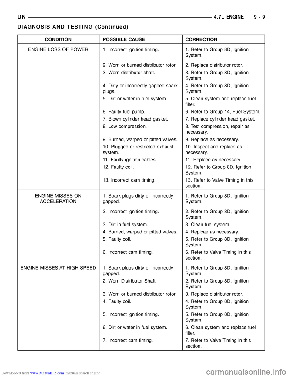
Downloaded from www.Manualslib.com manuals search engine CONDITION POSSIBLE CAUSE CORRECTION
ENGINE LOSS OF POWER 1. Incorrect ignition timing. 1. Refer to Group 8D, Ignition
System.
2. Worn or burned distributor rotor. 2. Replace distributor rotor.
3. Worn distributor shaft. 3. Refer to Group 8D, Ignition
System.
4. Dirty or incorrectly gapped spark
plugs.4. Refer to Group 8D, Ignition
System.
5. Dirt or water in fuel system. 5. Clean system and replace fuel
filter.
6. Faulty fuel pump. 6. Refer to Group 14, Fuel System.
7. Blown cylinder head gasket. 7. Replace cylinder head gasket.
8. Low compression. 8. Test compression, repair as
necessary.
9. Burned, warped or pitted valves. 9. Replace as necessary.
10. Plugged or restricted exhaust
system.10. Inspect and replace as
necessary.
11. Faulty ignition cables. 11. Replace as necessary.
12. Faulty coil. 12. Refer to Group 8D, Ignition
System.
13. Incorrect cam timing. 13. Refer to Valve Timing in this
section.
ENGINE MISSES ON
ACCELERATION1. Spark plugs dirty or incorrectly
gapped.1. Refer to Group 8D, Ignition
System.
2. Incorrect ignition timing. 2. Refer to Group 8D, Ignition
System.
3. Dirt in fuel system. 3. Clean fuel system.
4. Burned, warped or pitted valves. 4. Replcae as necessary.
5. Faulty coil. 5. Refer to Group 8D, Ignition
System.
6. Incorrect cam timing. 6. Refer to Valve Timing in this
section.
ENGINE MISSES AT HIGH SPEED 1. Spark plugs dirty or incorrectly
gapped.1. Refer to Group 8D, Ignition
System.
2. Worn Distributor Shaft. 2. Refer to Group 8D, Ignition
System.
3. Worn or burned distributor rotor. 3. Replace distributor rotor.
4. Faulty coil. 4. Refer to Group 8D, Ignition
System.
5. Incorrect ignition timing. 5. Refer to Group 8D, Ignition
System.
6. Dirt or water in fuel system. 6. Clean system and replace fuel
filter.
7. Incorrect cam timing. 7. Refer to Valve Timing in this
section.
DN4.7L ENGINE 9 - 9
DIAGNOSIS AND TESTING (Continued)
Page 11 of 193
Downloaded from www.Manualslib.com manuals search engine SERVICE DIAGNOSISÐLUBRICATION
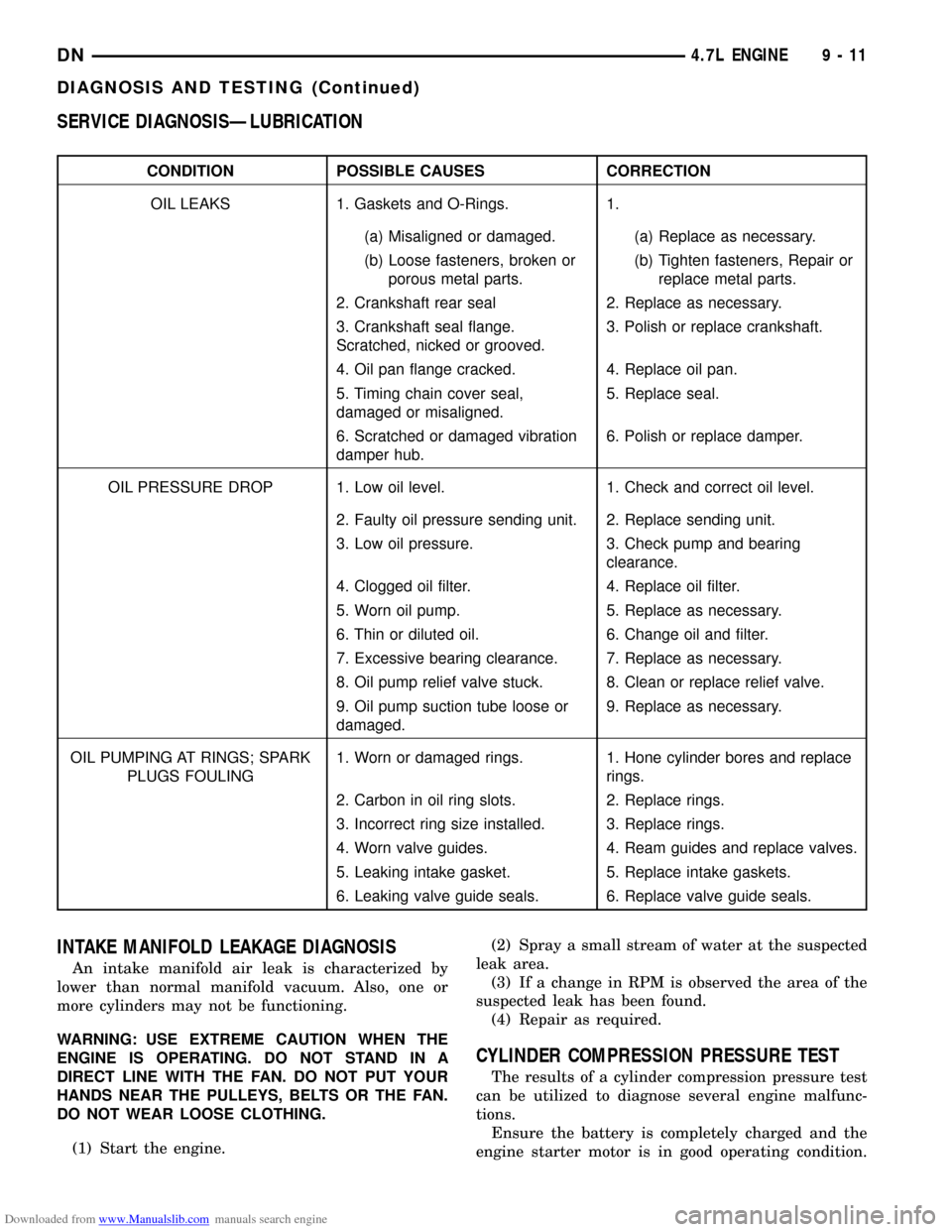
CONDITION POSSIBLE CAUSES CORRECTION
OIL LEAKS 1. Gaskets and O-Rings. 1.
(a) Misaligned or damaged. (a) Replace as necessary.
(b) Loose fasteners, broken or
porous metal parts.(b) Tighten fasteners, Repair or
replace metal parts.
2. Crankshaft rear seal 2. Replace as necessary.
3. Crankshaft seal flange.
Scratched, nicked or grooved.3. Polish or replace crankshaft.
4. Oil pan flange cracked. 4. Replace oil pan.
5. Timing chain cover seal,
damaged or misaligned.5. Replace seal.
6. Scratched or damaged vibration
damper hub.6. Polish or replace damper.
OIL PRESSURE DROP 1. Low oil level. 1. Check and correct oil level.
2. Faulty oil pressure sending unit. 2. Replace sending unit.
3. Low oil pressure. 3. Check pump and bearing
clearance.
4. Clogged oil filter. 4. Replace oil filter.
5. Worn oil pump. 5. Replace as necessary.
6. Thin or diluted oil. 6. Change oil and filter.
7. Excessive bearing clearance. 7. Replace as necessary.
8. Oil pump relief valve stuck. 8. Clean or replace relief valve.
9. Oil pump suction tube loose or
damaged.9. Replace as necessary.
OIL PUMPING AT RINGS; SPARK
PLUGS FOULING1. Worn or damaged rings. 1. Hone cylinder bores and replace
rings.
2. Carbon in oil ring slots. 2. Replace rings.
3. Incorrect ring size installed. 3. Replace rings.
4. Worn valve guides. 4. Ream guides and replace valves.
5. Leaking intake gasket. 5. Replace intake gaskets.
6. Leaking valve guide seals. 6. Replace valve guide seals.
INTAKE MANIFOLD LEAKAGE DIAGNOSIS
An intake manifold air leak is characterized by
lower than normal manifold vacuum. Also, one or
more cylinders may not be functioning.
WARNING: USE EXTREME CAUTION WHEN THE
ENGINE IS OPERATING. DO NOT STAND IN A
DIRECT LINE WITH THE FAN. DO NOT PUT YOUR
HANDS NEAR THE PULLEYS, BELTS OR THE FAN.
DO NOT WEAR LOOSE CLOTHING.
(1) Start the engine.(2) Spray a small stream of water at the suspected
leak area.
(3) If a change in RPM is observed the area of the
suspected leak has been found.
(4) Repair as required.
CYLINDER COMPRESSION PRESSURE TEST
The results of a cylinder compression pressure test
can be utilized to diagnose several engine malfunc-
tions.
Ensure the battery is completely charged and the
engine starter motor is in good operating condition.
DN4.7L ENGINE 9 - 11
DIAGNOSIS AND TESTING (Continued)
Page 12 of 193
Downloaded from www.Manualslib.com manuals search engine Otherwise the indicated compression pressures may
not be valid for diagnosis purposes.
(1) Clean the spark plug recesses with compressed
air.
(2) Remove the spark plugs.
(3) Secure the throttle in the wide-open position.
(4) Disable the fuel system. (Refer to Group 14,
Fuel System for the correct procedure)
(5) Disconnect the ignition coil.
(6) Insert a compression pressure gauge and rotate
the engine with the engine starter motor for three
revolutions.
(7) Record the compression pressure on the 3rd
revolution. Continue the test for the remaining cylin-
ders.
Refer to Engine Specifications for the correct
engine compression pressures.
CYLINDER HEAD GASKET FAILURE DIAGNOSIS
A cylinder head gasket leak can be located between
adjacent cylinders or between a cylinder and the
adjacent water jacket.
²Possible indications of the cylinder head gasket
leaking between adjacent cylinders are:
²Loss of engine power
²Engine misfiring
²Poor fuel economy
²Possible indications of the cylinder head gasket
leaking between a cylinder and an adjacent water
jacket are:
²Engine overheating
²Loss of coolant
²Excessive steam (white smoke) emitting from
exhaust
²Coolant foaming
CYLINDER-TO-CYLINDER LEAKAGE TEST
To determine if an engine cylinder head gasket is
leaking between adjacent cylinders, follow the proce-
dures in Cylinder Compression Pressure Test in this
section. An engine cylinder head gasket leaking
between adjacent cylinders will result in approxi-
mately a 50±70% reduction in compression pressure.
CYLINDER-TO-WATER JACKET LEAKAGE TEST
WARNING: USE EXTREME CAUTION WHEN THE
ENGINE IS OPERATING WITH COOLANT PRES-
SURE CAP REMOVED.
VISUAL TEST METHOD
With the engine cool, remove the coolant pressure
cap. Start the engine and allow it to warm up until
thermostat opens.
If a large combustion/compression pressure leak
exists, bubbles will be visible in the coolant.COOLING SYSTEM TESTER METHOD
WARNING: WITH COOLING SYSTEM TESTER IN
PLACE, PRESSURE WILL BUILD UP FAST. EXCES-
SIVE PRESSURE BUILT UP, BY CONTINUOUS
ENGINE OPERATION, MUST BE RELEASED TO A
SAFE PRESSURE POINT. NEVER PERMIT PRES-
SURE TO EXCEED 138 kPa (20 psi).
Install Cooling System Tester 7700 or equivalent to
pressure cap neck. Start the engine and observe the
tester's pressure gauge. If gauge pulsates with every
power stroke of a cylinder a combustion pressure
leak is evident.
CHEMICAL TEST METHOD
Combustion leaks into the cooling system can also
be checked by using Bloc-Chek Kit C-3685-A or
equivalent. Perform test following the procedures
supplied with the tool kit.
CYLINDER COMBUSTION PRESSURE LEAKAGE
TEST
The combustion pressure leakage test provides an
accurate means for determining engine condition.
Combustion pressure leakage testing will detect:
²Exhaust and intake valve leaks (improper seat-
ing).
²Leaks between adjacent cylinders or into water
jacket.
²Any causes for combustion/compression pressure
loss.
(1) Check the coolant level and fill as required. DO
NOT install the radiator cap.
(2) Start and operate the engine until it attains
normal operating temperature, then turn the engine
OFF.
(3) Remove the spark plugs.
(4) Remove the oil filler cap.
(5) Remove the air cleaner.
(6)
Calibrate the tester according to the manufacturer's
instructions. The shop air source for testing should main-
tain 483 kPa (70 psi) minimum, 1,379 kPa (200 psi) maxi-
mum and 552 kPa (80 psi) recommended.
(7) Perform the test procedures on each cylinder
according to the tester manufacturer's instructions.
While testing, listen for pressurized air escaping
through the throttle body, tailpipe and oil filler cap
opening. Check for bubbles in the radiator coolant.
All gauge pressure indications should be equal,
with no more than 25% leakage.
FOR EXAMPLE:At 552 kPa (80 psi) input pres-
sure, a minimum of 414 kPa (60 psi) should be main-
tained in the cylinder.
Refer to the Cylinder Combustion Pressure Leak-
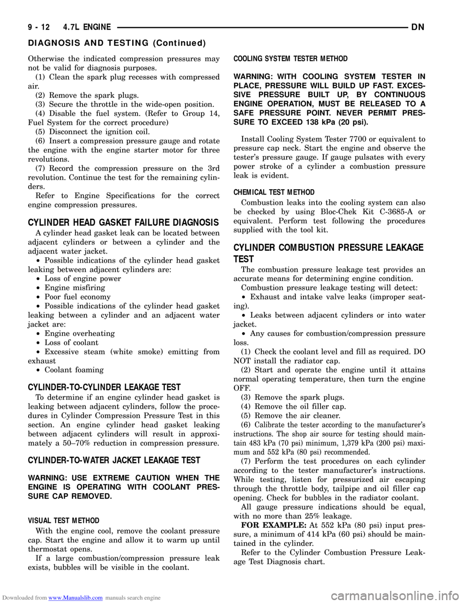
age Test Diagnosis chart.
9 - 12 4.7L ENGINEDN
DIAGNOSIS AND TESTING (Continued)