Diff DODGE DURANGO 2000 1.G User Guide
[x] Cancel search | Manufacturer: DODGE, Model Year: 2000, Model line: DURANGO, Model: DODGE DURANGO 2000 1.GPages: 193, PDF Size: 5.65 MB
Page 115 of 193
Downloaded from www.Manualslib.com manuals search engine After the distributor has been installed, its rota-
tional position must be set using theSET SYNC
mode of the DRB scan tool. Refer to Checking Dis-
tributor Position following the Distributor Installa-
tion section in Group 8D, Ignition system.
Do not attempt to adjust ignition timing by
rotating the distributor. It has no effect on igni-
tion timing. Adjusting distributor position will
effect fuel synchronization only.
OIL PAN
REMOVAL
2WD
(1) Disconnect the negative cable from the battery.
(2) Remove air cleaner assembly.
(3) Remove engine oil dipstick.
(4) Disconnect distributor cap and position away
from cowl.
(5) Remove the fan shroud. Refer to COOLING
SYSTEM.
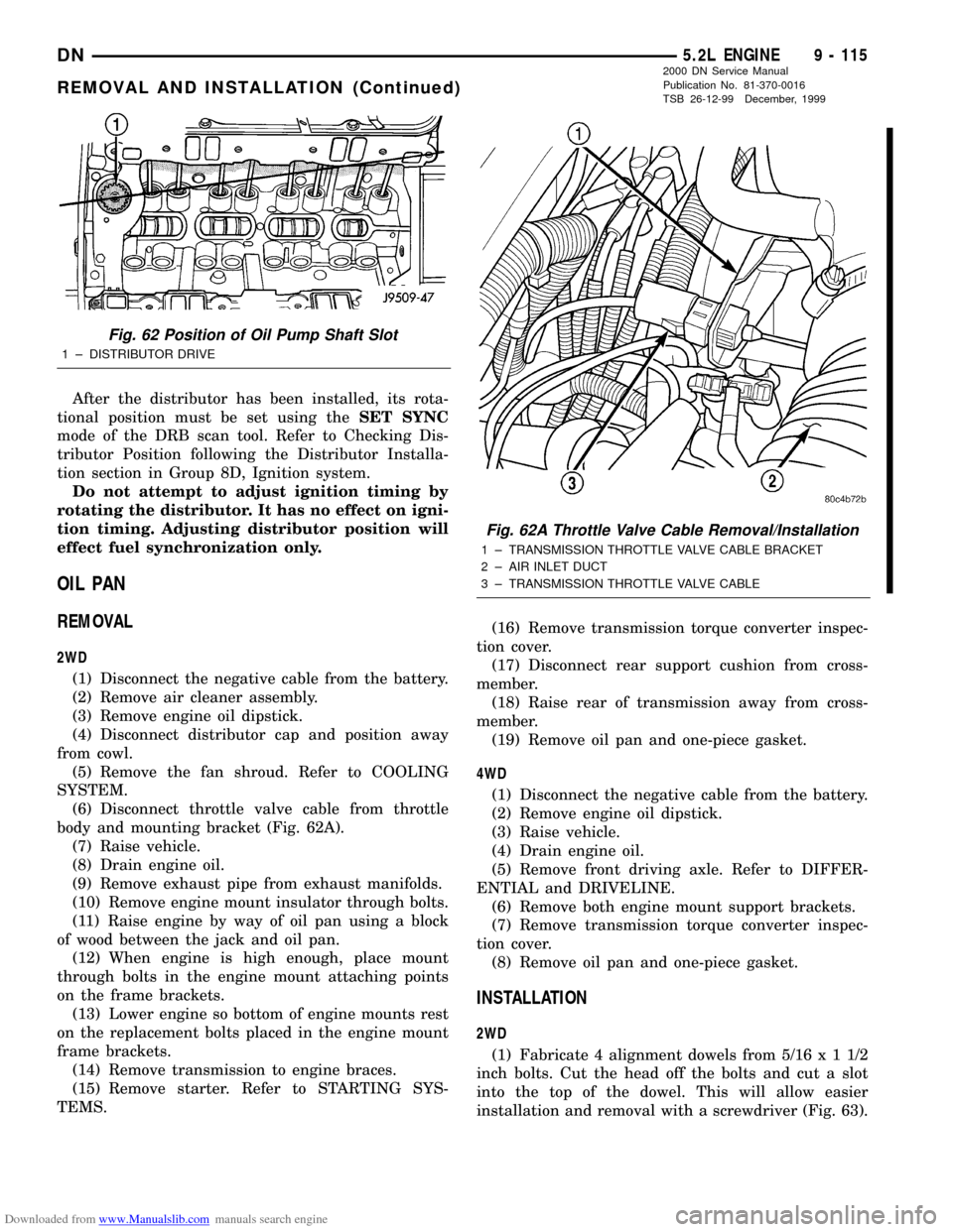
(6) Disconnect throttle valve cable from throttle
body and mounting bracket (Fig. 62A).
(7) Raise vehicle.
(8) Drain engine oil.
(9) Remove exhaust pipe from exhaust manifolds.
(10) Remove engine mount insulator through bolts.
(11) Raise engine by way of oil pan using a block
of wood between the jack and oil pan.
(12) When engine is high enough, place mount
through bolts in the engine mount attaching points
on the frame brackets.
(13) Lower engine so bottom of engine mounts rest
on the replacement bolts placed in the engine mount
frame brackets.
(14) Remove transmission to engine braces.
(15) Remove starter. Refer to STARTING SYS-
TEMS.(16) Remove transmission torque converter inspec-
tion cover.
(17) Disconnect rear support cushion from cross-
member.
(18) Raise rear of transmission away from cross-
member.
(19) Remove oil pan and one-piece gasket.
4WD
(1) Disconnect the negative cable from the battery.
(2) Remove engine oil dipstick.
(3) Raise vehicle.
(4) Drain engine oil.
(5) Remove front driving axle. Refer to DIFFER-
ENTIAL and DRIVELINE.
(6) Remove both engine mount support brackets.
(7) Remove transmission torque converter inspec-
tion cover.
(8) Remove oil pan and one-piece gasket.
INSTALLATION
2WD
(1) Fabricate 4 alignment dowels from 5/16x11/2
inch bolts. Cut the head off the bolts and cut a slot
into the top of the dowel. This will allow easier
installation and removal with a screwdriver (Fig. 63).
Fig. 62 Position of Oil Pump Shaft Slot
1 ± DISTRIBUTOR DRIVE
Fig. 62A Throttle Valve Cable Removal/Installation
1 ± TRANSMISSION THROTTLE VALVE CABLE BRACKET
2 ± AIR INLET DUCT
3 ± TRANSMISSION THROTTLE VALVE CABLE
DN5.2L ENGINE 9 - 115
REMOVAL AND INSTALLATION (Continued)
2000 DN Service Manual
Publication No. 81-370-0016
TSB 26-12-99 December, 1999
Page 116 of 193
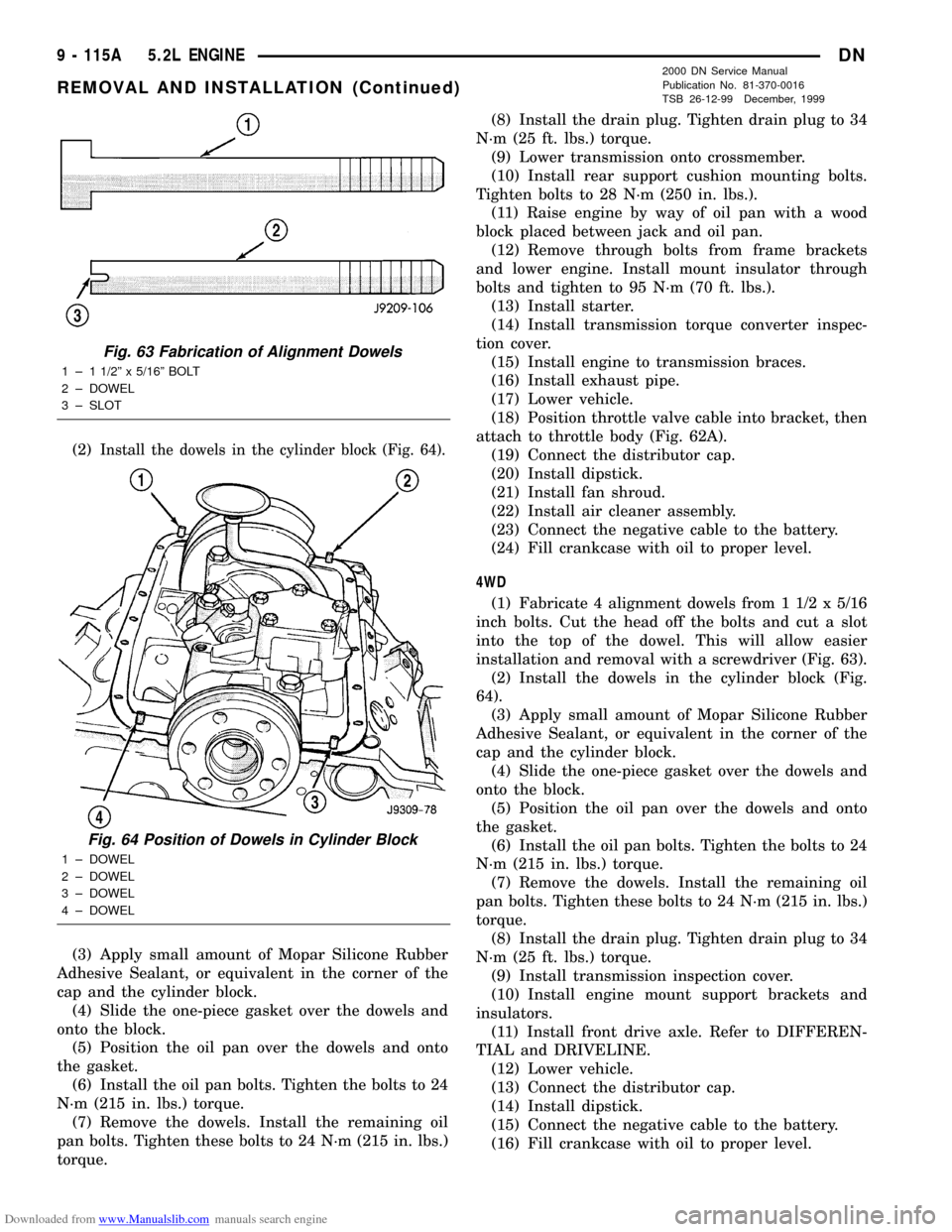
Downloaded from www.Manualslib.com manuals search engine (2)Install the dowels in the cylinder block (Fig. 64).
(3) Apply small amount of Mopar Silicone Rubber
Adhesive Sealant, or equivalent in the corner of the
cap and the cylinder block.
(4) Slide the one-piece gasket over the dowels and
onto the block.
(5) Position the oil pan over the dowels and onto
the gasket.
(6) Install the oil pan bolts. Tighten the bolts to 24
N´m (215 in. lbs.) torque.
(7) Remove the dowels. Install the remaining oil
pan bolts. Tighten these bolts to 24 N´m (215 in. lbs.)
torque.(8) Install the drain plug. Tighten drain plug to 34
N´m (25 ft. lbs.) torque.
(9) Lower transmission onto crossmember.
(10) Install rear support cushion mounting bolts.
Tighten bolts to 28 N´m (250 in. lbs.).
(11) Raise engine by way of oil pan with a wood
block placed between jack and oil pan.
(12) Remove through bolts from frame brackets
and lower engine. Install mount insulator through
bolts and tighten to 95 N´m (70 ft. lbs.).
(13) Install starter.
(14) Install transmission torque converter inspec-
tion cover.
(15) Install engine to transmission braces.
(16) Install exhaust pipe.
(17) Lower vehicle.
(18) Position throttle valve cable into bracket, then
attach to throttle body (Fig. 62A).
(19) Connect the distributor cap.
(20) Install dipstick.
(21) Install fan shroud.
(22) Install air cleaner assembly.
(23) Connect the negative cable to the battery.
(24) Fill crankcase with oil to proper level.
4WD
(1) Fabricate 4 alignment dowels from 1 1/2 x 5/16
inch bolts. Cut the head off the bolts and cut a slot
into the top of the dowel. This will allow easier
installation and removal with a screwdriver (Fig. 63).
(2) Install the dowels in the cylinder block (Fig.
64).
(3) Apply small amount of Mopar Silicone Rubber
Adhesive Sealant, or equivalent in the corner of the
cap and the cylinder block.
(4) Slide the one-piece gasket over the dowels and
onto the block.
(5) Position the oil pan over the dowels and onto
the gasket.
(6) Install the oil pan bolts. Tighten the bolts to 24
N´m (215 in. lbs.) torque.
(7) Remove the dowels. Install the remaining oil
pan bolts. Tighten these bolts to 24 N´m (215 in. lbs.)
torque.
(8) Install the drain plug. Tighten drain plug to 34
N´m (25 ft. lbs.) torque.
(9) Install transmission inspection cover.
(10) Install engine mount support brackets and
insulators.
(11) Install front drive axle. Refer to DIFFEREN-
TIAL and DRIVELINE.
(12) Lower vehicle.
(13) Connect the distributor cap.
(14) Install dipstick.
(15) Connect the negative cable to the battery.
(16) Fill crankcase with oil to proper level.
Fig. 63 Fabrication of Alignment Dowels
1 ± 1 1/2º x 5/16º BOLT
2 ± DOWEL
3 ± SLOT
Fig. 64 Position of Dowels in Cylinder Block
1 ± DOWEL
2 ± DOWEL
3 ± DOWEL
4 ± DOWEL
9 - 115A 5.2L ENGINEDN
REMOVAL AND INSTALLATION (Continued)
2000 DN Service Manual
Publication No. 81-370-0016
TSB 26-12-99 December, 1999
Page 148 of 193
Downloaded from www.Manualslib.com manuals search engine All gauge pressure indications should be equal,
with no more than 25% leakage.
FOR EXAMPLE:At 552 kPa (80 psi) input pres-
sure, a minimum of 414 kPa (60 psi) should be main-
tained in the cylinder.
Refer to the Cylinder Combustion Pressure Leak-
age Test Diagnosis chart.
INSPECTION (ENGINE OIL LEAKS IN GENERAL)
Begin with a through visual inspection of the
engine, particularly at the area of the suspected leak.
If an oil leak source is not readily identifiable, the
following steps should be followed:
(1) Do not clean or degrease the engine at this
time because some solvents may cause rubber to
swell, temporarily stopping the leak.
(2) Add an oil-soluble dye (use as recommended by
manufacturer). Start the engine and let idle for
approximately 15 minutes. Check the oil dipstick to
be sure the dye is thoroughly mixed as indicated
with a bright yellow color under a black light source.
(3) Using a black light, inspect the entire engine
for fluorescent dye, particularly at the suspected area
of oil leak. If the oil leak is found and identified,
repair per service manual instructions.
(4) If dye is not observed, drive the vehicle at var-
ious speeds for approximately 24km (15 miles), and
repeat previous step.
(5) If the oil leak source is not positively identified
at this time, proceed with the air leak detection test
method as follows:
(6) Disconnect the breather cap to air cleaner hose
at the breather cap end. Cap or plug breather cap
nipple.
(7) Remove the PCV valve from the cylinder head
cover. Cap or plug the PCV valve grommet.
(8) Attach an air hose with pressure gauge and
regulator to the dipstick tube.
CAUTION: Do not subject the engine assembly to
more than 20.6 kpa (3 PSI) of test pressure.
(9) Gradually apply air pressure from 1 psi to 2.5
psi maximum while applying soapy water at the sus-
pected source. Adjust the regulator to the suitable
test pressure that provide the best bubbles which
will pinpoint the leak source. If the oil leak is
detected and identified, repair per service manual
procedures.
(10) If the leakage occurs at the rear oil seal area,
refer to the section, Inspection for Rear Seal Area
Leak.
(11) If no leaks are detected, turn off the air sup-
ply and remove the air hose and all plugs and caps.
Install the PCV valve and breather cap hose. Proceed
to next step.(12) Clean the oil off the suspect oil leak area
using a suitable solvent. Drive the vehicle at various
speeds approximately 24 km (15 miles). Inspect the
engine for signs of an oil leak by using a black light.
REAR SEAL AREA LEAKSÐINSPECTION
Since it is sometimes difficult to determine the
source of an oil leak in the rear seal area of the
engine, a more involved inspection is necessary. The
following steps should be followed to help pinpoint
the source of the leak.
If the leakage occurs at the crankshaft rear oil seal
area:
(1) Disconnect the battery.
(2) Raise the vehicle.
(3) Remove torque converter or clutch housing
cover and inspect rear of block for evidence of oil.
Use a black light to check for the oil leak:
(a) Circular spray pattern generally indicates
seal leakage or crankshaft damage.
(b) Where leakage tends to run straight down,
possible causes are a porous block, distributor seal,
camshaft bore cup plugs, oil galley pipe plugs, oil
filter runoff, and main bearing cap to cylinder
block mating surfaces. See Group 9, Engines, for
proper repair procedures of these items.
(4) If no leaks are detected, pressurized the crank-
case as outlined in the section, Inspection (Engine oil
Leaks in general)
CAUTION: Do not exceed 20.6 kPa (3 psi).
(5) If the leak is not detected, very slowly turn the
crankshaft and watch for leakage. If a leak is
detected between the crankshaft and seal while
slowly turning the crankshaft, it is possible the
crankshaft seal surface is damaged. The seal area on
the crankshaft could have minor nicks or scratches
that can be polished out with emery cloth.
CAUTION: Use extreme caution when crankshaft
polishing is necessary to remove minor nicks or
scratches. The crankshaft seal flange is specially
machined to complement the function of the rear oil
seal.
(6) For bubbles that remain steady with shaft
rotation, no further inspection can be done until dis-
assembled. Refer to the service DiagnosisÐMechani-
cal, under the Oil Leak row, for components
inspections on possible causes and corrections.
(7) After the oil leak root cause and appropriate
corrective action have been identified, Refer to Group
9, EnginesÐCrankshaft Rear Oil Seals, for proper
replacement procedures.
DN5.9L ENGINE 9 - 147
DIAGNOSIS AND TESTING (Continued)
Page 150 of 193
Downloaded from www.Manualslib.com manuals search engine (2) Install Oil Pressure Line and Gauge Tool
C-3292. Start engine and record pressure. Refer to
Oil Pressure in Engine Specifications for the proper
pressures.
SERVICE PROCEDURES
FORM-IN-PLACE GASKETS
There are several places where form-in-place gas-
kets are used on the engine.DO NOT use form-in-
place gasket material unless specified.Care
must be taken when applying form-in-place gaskets.
Bead size, continuity and location are of great impor-
tance. Too thin a bead can result in leakage while too
much can result in spill-over. A continuous bead of
the proper width is essential to obtain a leak-free
joint.
Two types of form-in-place gasket materials are
used in the engine area (Mopar Silicone Rubber
Adhesive Sealant and Mopar Gasket Maker). Each
have different properties and cannot be used inter-
changeably.
MOPAR SILICONE RUBBER ADHESIVE SEALANT
Mopar Silicone Rubber Adhesive Sealant, normally
black in color, is available in 3 ounce tubes. Moisture
in the air causes the sealant material to cure. This
material is normally used on flexible metal flanges.
It has a shelf life of a year and will not properly cure
if over aged. Always inspect the package for the expi-
ration date before use.
MOPAR GASKET MAKER
Mopar Gasket Maker, normally red in color, is
available in 6 cc tubes. This anaerobic type gasket
material cures in the absence of air when squeezed
between smooth machined metallic surfaces. It will
not cure if left in the uncovered tube. DO NOT use
on flexible metal flanges.
SURFACE PREPARATION
Parts assembled with form-in-place gaskets may be
disassembled without unusual effort. In some
instances, it may be necessary to lightly tap the part
with a mallet or other suitable tool to break the seal
between the mating surfaces. A flat gasket scraper
may also be lightly tapped into the joint but care
must be taken not to damage the mating surfaces.
Scrape or wire brush all gasket surfaces to remove
all loose material. Inspect stamped parts to ensure
gasket rails are flat. Flatten rails with a hammer on
a flat plate, if required. Gasket surfaces must be free
of oil and dirt. Make sure the old gasket material is
removed from blind attaching holes.
GASKET APPLICATION
Assembling parts using a form-in-place gasket
requires care.
Mopar Silicone Rubber Adhesive Sealant should be
applied in a continuous bead approximately 3 mm
(0.12 inch) in diameter. All mounting holes must be
circled. For corner sealing,a3or6mm(1/8 or 1/4
inch) drop is placed in the center of the gasket con-
tact area. Uncured sealant may be removed with a
shop towel. Components should be torqued in place
while the sealant is still wet to the touch (within 10
minutes). The use of a locating dowel is recom-
mended during assembly to prevent smearing the
material off location.
Mopar Gasket Maker should be applied sparingly
to one gasket surface. The sealant diameter should
be 1.00 mm (0.04 inch) or less. Be certain the mate-
rial surrounds each mounting hole. Excess material
can easily be wiped off. Components should be
torqued in place within 15 minutes. The use of a
locating dowel is recommended during assembly to
prevent smearing the material off location.
ENGINE PERFORMANCE
It is important that the vehicle is operating to its
optimum performance level to maintain fuel economy
and the lowest emission levels. If vehicle is not oper-
ating to these standards, refer to Engine Diagnosis
outlined in this section. The following procedures can
assist in achieving the proper engine diagnosis.
(1) Test cranking amperage draw. Refer to Electri-
cal Group 8B, Cold Cranking Test.
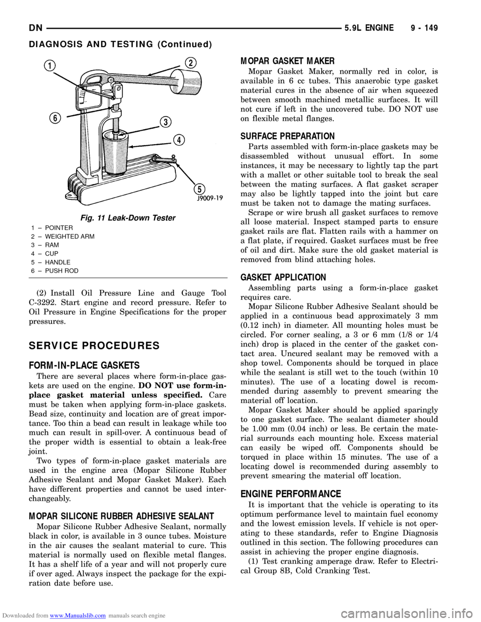
Fig. 11 Leak-Down Tester
1 ± POINTER
2 ± WEIGHTED ARM
3 ± RAM
4 ± CUP
5 ± HANDLE
6 ± PUSH ROD
DN5.9L ENGINE 9 - 149
DIAGNOSIS AND TESTING (Continued)
Page 160 of 193
Downloaded from www.Manualslib.com manuals search engine REMOVALÐ4WD
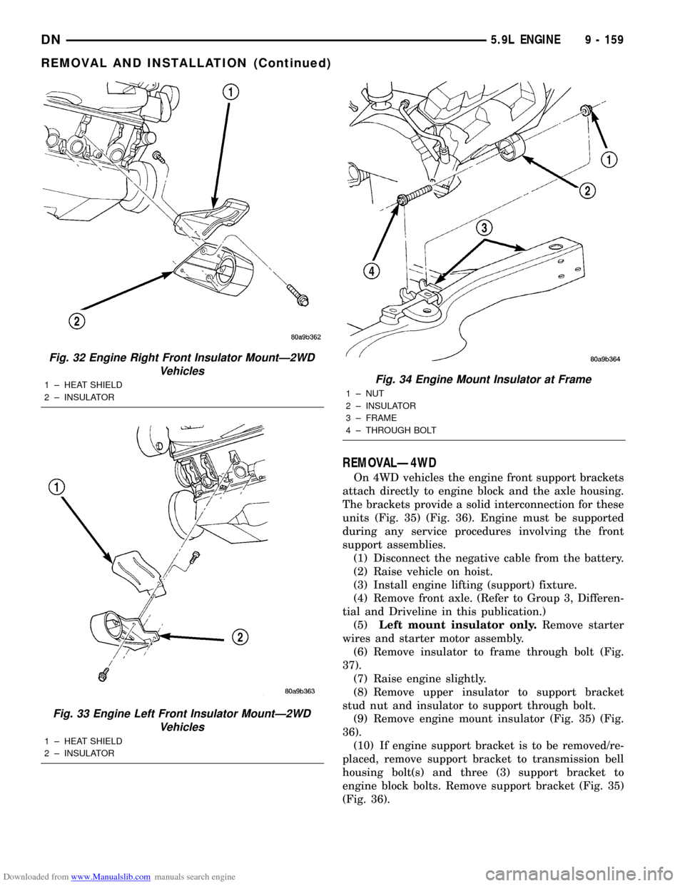
On 4WD vehicles the engine front support brackets
attach directly to engine block and the axle housing.
The brackets provide a solid interconnection for these
units (Fig. 35) (Fig. 36). Engine must be supported
during any service procedures involving the front
support assemblies.
(1) Disconnect the negative cable from the battery.
(2) Raise vehicle on hoist.
(3) Install engine lifting (support) fixture.
(4) Remove front axle. (Refer to Group 3, Differen-
tial and Driveline in this publication.)
(5)Left mount insulator only.Remove starter
wires and starter motor assembly.
(6) Remove insulator to frame through bolt (Fig.
37).
(7) Raise engine slightly.
(8) Remove upper insulator to support bracket
stud nut and insulator to support through bolt.
(9) Remove engine mount insulator (Fig. 35) (Fig.
36).
(10) If engine support bracket is to be removed/re-
placed, remove support bracket to transmission bell
housing bolt(s) and three (3) support bracket to
engine block bolts. Remove support bracket (Fig. 35)
(Fig. 36).
Fig. 32 Engine Right Front Insulator MountÐ2WD
Vehicles
1 ± HEAT SHIELD
2 ± INSULATOR
Fig. 33 Engine Left Front Insulator MountÐ2WD
Vehicles
1 ± HEAT SHIELD
2 ± INSULATOR
Fig. 34 Engine Mount Insulator at Frame
1 ± NUT
2 ± INSULATOR
3 ± FRAME
4 ± THROUGH BOLT
DN5.9L ENGINE 9 - 159
REMOVAL AND INSTALLATION (Continued)
Page 161 of 193
Downloaded from www.Manualslib.com manuals search engine INSTALLATIONÐ4WD
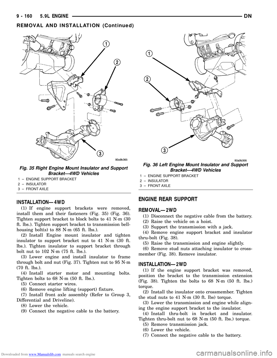
(1) If engine support brackets were removed,
install them and their fasteners (Fig. 35) (Fig. 36).
Tighten support bracket to block bolts to 41 N´m (30
ft. lbs.). Tighten support bracket to transmission bell-
housing bolt(s) to 88 N´m (65 ft. lbs.).
(2) Install Engine mount insulator and tighten
insulator to support bracket nut to 41 N´m (30 ft.
lbs.). Tighten insulator to support bracket through
bolt nut to 102 N´m (75 ft. lbs.).
(3) Lower engine and install insulator to frame
through bolt and nut (Fig. 37). Tighten nut to 95 N´m
(70 ft. lbs.).
(4) Install starter motor and mounting bolts.
Tighten bolts to 68 N´m (50 ft. lbs.).
(5) Connect starter wires.
(6) Remove engine lifting (support) fixture.
(7) Install front axle assembly (Refer to Group 3,
Differential and Driveline).
(8) Lower the vehicle.
(9) Connect the negative cable to the battery.
ENGINE REAR SUPPORT
REMOVALÐ2WD
(1) Disconnect the negative cable from the battery.
(2) Raise the vehicle on a hoist.
(3) Support the transmission with a jack.
(4) Remove engine support bracket and insulator
thru-bolt (Fig. 38).
(5) Raise the transmission and engine slightly.
(6) Remove stud nuts attaching insulator to cross-
member (Fig. 38). Remove insulator.
INSTALLATIONÐ2WD
(1) If the engine support bracket was removed,
position the bracket to the transmission extension
(Fig. 38). Tighten the bolts to 68 N´m (50 ft. lbs.)
torque.
(2) Install the insulator onto crossmember. Tighten
the stud nuts to 41 N´m (30 ft. lbs) torque.
(3) Lower the transmission and engine while align-
ing the engine support bracket to the insulator.
(4) Install thru-bolt in bracket and insulator.
Tighten thru-bolt nut to 68 N´m (50 ft. lbs.) torque.
(5) Remove transmission jack.
(6) Lower the vehicle.
(7) Connect the negative cable to the battery.
Fig. 35 Right Engine Mount Insulator and Support
BracketÐ4WD Vehicles
1 ± ENGINE SUPPORT BRACKET
2 ± INSULATOR
3 ± FRONT AXLE
Fig. 36 Left Engine Mount Insulator and Support
BracketÐ4WD Vehicles
1 ± ENGINE SUPPORT BRACKET
2 ± INSULATOR
3 ± FRONT AXLE
9 - 160 5.9L ENGINEDN
REMOVAL AND INSTALLATION (Continued)
Page 175 of 193
Downloaded from www.Manualslib.com manuals search engine CRANKSHAFT MAIN BEARINGS
REMOVAL
(1) Remove the oil pan.
(2) Remove the oil pump from the rear main bear-
ing cap.
(3) Identify bearing caps before removal. Remove
bearing caps one at a time.
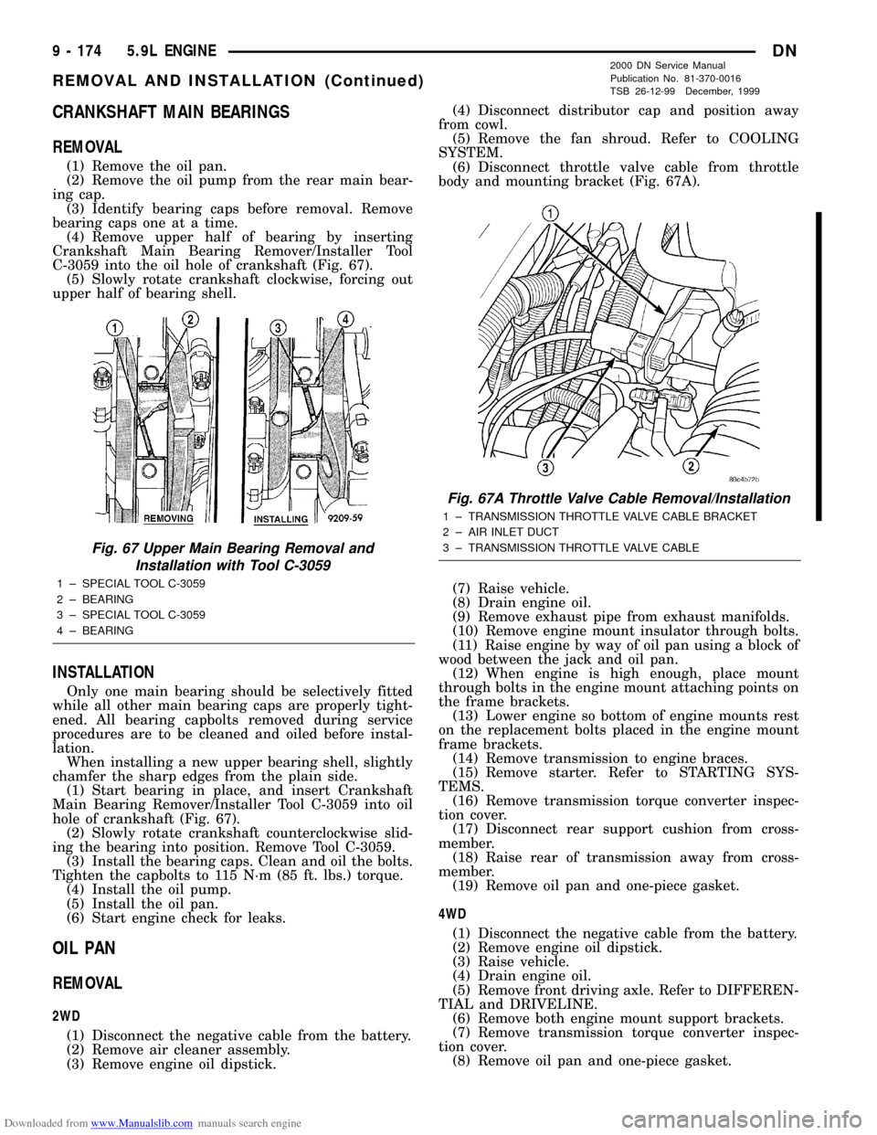
(4) Remove upper half of bearing by inserting
Crankshaft Main Bearing Remover/Installer Tool
C-3059 into the oil hole of crankshaft (Fig. 67).
(5) Slowly rotate crankshaft clockwise, forcing out
upper half of bearing shell.
INSTALLATION
Only one main bearing should be selectively fitted
while all other main bearing caps are properly tight-
ened. All bearing capbolts removed during service
procedures are to be cleaned and oiled before instal-
lation.
When installing a new upper bearing shell, slightly
chamfer the sharp edges from the plain side.
(1) Start bearing in place, and insert Crankshaft
Main Bearing Remover/Installer Tool C-3059 into oil
hole of crankshaft (Fig. 67).
(2) Slowly rotate crankshaft counterclockwise slid-
ing the bearing into position. Remove Tool C-3059.
(3) Install the bearing caps. Clean and oil the bolts.
Tighten the capbolts to 115 N´m (85 ft. lbs.) torque.
(4) Install the oil pump.
(5) Install the oil pan.
(6) Start engine check for leaks.
OIL PAN
REMOVAL
2WD
(1) Disconnect the negative cable from the battery.
(2) Remove air cleaner assembly.
(3) Remove engine oil dipstick.(4) Disconnect distributor cap and position away
from cowl.
(5) Remove the fan shroud. Refer to COOLING
SYSTEM.
(6) Disconnect throttle valve cable from throttle
body and mounting bracket (Fig. 67A).
(7) Raise vehicle.
(8) Drain engine oil.
(9) Remove exhaust pipe from exhaust manifolds.
(10) Remove engine mount insulator through bolts.
(11) Raise engine by way of oil pan using a block of
wood between the jack and oil pan.
(12) When engine is high enough, place mount
through bolts in the engine mount attaching points on
the frame brackets.
(13) Lower engine so bottom of engine mounts rest
on the replacement bolts placed in the engine mount
frame brackets.
(14) Remove transmission to engine braces.
(15) Remove starter. Refer to STARTING SYS-
TEMS.
(16) Remove transmission torque converter inspec-
tion cover.
(17) Disconnect rear support cushion from cross-
member.
(18) Raise rear of transmission away from cross-
member.
(19) Remove oil pan and one-piece gasket.
4WD
(1) Disconnect the negative cable from the battery.
(2) Remove engine oil dipstick.
(3) Raise vehicle.
(4) Drain engine oil.
(5) Remove front driving axle. Refer to DIFFEREN-
TIAL and DRIVELINE.
(6) Remove both engine mount support brackets.
(7) Remove transmission torque converter inspec-
tion cover.
(8) Remove oil pan and one-piece gasket.
Fig. 67 Upper Main Bearing Removal and
Installation with Tool C-3059
1 ± SPECIAL TOOL C-3059
2 ± BEARING
3 ± SPECIAL TOOL C-3059
4 ± BEARING
Fig. 67A Throttle Valve Cable Removal/Installation
1 ± TRANSMISSION THROTTLE VALVE CABLE BRACKET
2 ± AIR INLET DUCT
3 ± TRANSMISSION THROTTLE VALVE CABLE
9 - 174 5.9L ENGINEDN
REMOVAL AND INSTALLATION (Continued)
2000 DN Service Manual
Publication No. 81-370-0016
TSB 26-12-99 December, 1999
Page 176 of 193
Downloaded from www.Manualslib.com manuals search engine INSTALLATION
2WD
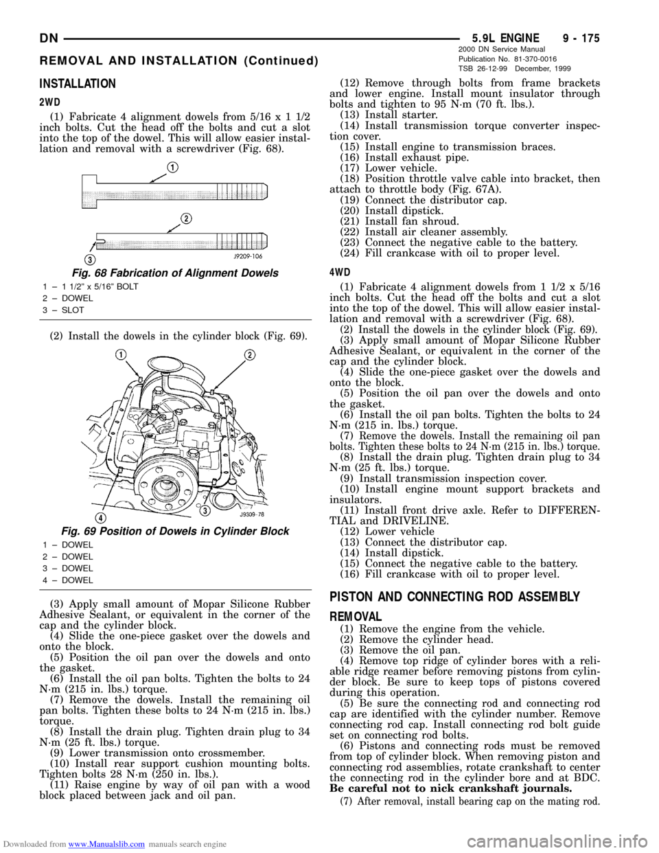
(1) Fabricate 4 alignment dowels from 5/16x11/2
inch bolts. Cut the head off the bolts and cut a slot
into the top of the dowel. This will allow easier instal-
lation and removal with a screwdriver (Fig. 68).
(2) Install the dowels in the cylinder block (Fig. 69).
(3) Apply small amount of Mopar Silicone Rubber
Adhesive Sealant, or equivalent in the corner of the
cap and the cylinder block.
(4) Slide the one-piece gasket over the dowels and
onto the block.
(5) Position the oil pan over the dowels and onto
the gasket.
(6) Install the oil pan bolts. Tighten the bolts to 24
N´m (215 in. lbs.) torque.
(7) Remove the dowels. Install the remaining oil
pan bolts. Tighten these bolts to 24 N´m (215 in. lbs.)
torque.
(8) Install the drain plug. Tighten drain plug to 34
N´m (25 ft. lbs.) torque.
(9) Lower transmission onto crossmember.
(10) Install rear support cushion mounting bolts.
Tighten bolts 28 N´m (250 in. lbs.).
(11) Raise engine by way of oil pan with a wood
block placed between jack and oil pan.(12) Remove through bolts from frame brackets
and lower engine. Install mount insulator through
bolts and tighten to 95 N´m (70 ft. lbs.).
(13) Install starter.
(14) Install transmission torque converter inspec-
tion cover.
(15) Install engine to transmission braces.
(16) Install exhaust pipe.
(17) Lower vehicle.
(18) Position throttle valve cable into bracket, then
attach to throttle body (Fig. 67A).
(19) Connect the distributor cap.
(20) Install dipstick.
(21) Install fan shroud.
(22) Install air cleaner assembly.
(23) Connect the negative cable to the battery.
(24) Fill crankcase with oil to proper level.
4WD
(1) Fabricate 4 alignment dowels from 1 1/2 x 5/16
inch bolts. Cut the head off the bolts and cut a slot
into the top of the dowel. This will allow easier instal-
lation and removal with a screwdriver (Fig. 68).
(2) Install the dowels in the cylinder block (Fig. 69).(3) Apply small amount of Mopar Silicone Rubber
Adhesive Sealant, or equivalent in the corner of the
cap and the cylinder block.
(4) Slide the one-piece gasket over the dowels and
onto the block.
(5) Position the oil pan over the dowels and onto
the gasket.
(6) Install the oil pan bolts. Tighten the bolts to 24
N´m (215 in. lbs.) torque.
(7)
Remove the dowels. Install the remaining oil pan
bolts. Tighten these bolts to 24 N´m (215 in. lbs.) torque.
(8) Install the drain plug. Tighten drain plug to 34
N´m (25 ft. lbs.) torque.
(9) Install transmission inspection cover.
(10) Install engine mount support brackets and
insulators.
(11) Install front drive axle. Refer to DIFFEREN-
TIAL and DRIVELINE.
(12) Lower vehicle
(13) Connect the distributor cap.
(14) Install dipstick.
(15) Connect the negative cable to the battery.
(16) Fill crankcase with oil to proper level.
PISTON AND CONNECTING ROD ASSEMBLY
REMOVAL
(1) Remove the engine from the vehicle.
(2) Remove the cylinder head.
(3) Remove the oil pan.
(4) Remove top ridge of cylinder bores with a reli-
able ridge reamer before removing pistons from cylin-
der block. Be sure to keep tops of pistons covered
during this operation.
(5) Be sure the connecting rod and connecting rod
cap are identified with the cylinder number. Remove
connecting rod cap. Install connecting rod bolt guide
set on connecting rod bolts.
(6) Pistons and connecting rods must be removed
from top of cylinder block. When removing piston and
connecting rod assemblies, rotate crankshaft to center
the connecting rod in the cylinder bore and at BDC.
Be careful not to nick crankshaft journals.
(7) After removal, install bearing cap on the mating rod.
Fig. 68 Fabrication of Alignment Dowels
1 ± 1 1/2º x 5/16º BOLT
2 ± DOWEL
3 ± SLOT
Fig. 69 Position of Dowels in Cylinder Block
1 ± DOWEL
2 ± DOWEL
3 ± DOWEL
4 ± DOWEL
DN5.9L ENGINE 9 - 175
REMOVAL AND INSTALLATION (Continued)
2000 DN Service Manual
Publication No. 81-370-0016
TSB 26-12-99 December, 1999