Diff DODGE DURANGO 2000 1.G Workshop Manual
[x] Cancel search | Manufacturer: DODGE, Model Year: 2000, Model line: DURANGO, Model: DODGE DURANGO 2000 1.GPages: 193, PDF Size: 5.65 MB
Page 2 of 193
Downloaded from www.Manualslib.com manuals search engine OIL PUMP..............................69
ENGINE OIL PRESSURE SENDING UNIT......70
CRANKSHAFT OIL SEALÐFRONT............70
CRANKSHAFT OIL SEALÐREAR.............73
ENGINE CORE PLUGS....................74
DISASSEMBLY AND ASSEMBLY
OIL PUMP..............................74
CLEANING AND INSPECTION
INTAKE MANIFOLD.......................75
EXHAUST MANIFOLD.....................75CYLINDER HEADS........................75
PISTON AND CONNECTING ROD............76
OILPAN................................76
OIL PUMP..............................76
CYLINDER BLOCK........................76
SPECIFICATIONS
4.7L ENGINE............................78
TORQUE...............................81
SPECIAL TOOLS
4.7L ENGINE............................82
DESCRIPTION AND OPERATION
ENGINE
DESCRIPTION
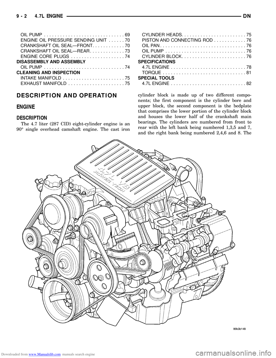
The 4.7 liter (287 CID) eight-cylinder engine is an
90É single overhead camshaft engine. The cast ironcylinder block is made up of two different compo-
nents; the first component is the cylinder bore and
upper block, the second component is the bedplate
that comprises the lower portion of the cylinder block
and houses the lower half of the crankshaft main
bearings. The cylinders are numbered from front to
rear with the left bank being numbered 1,3,5 and 7,
and the right bank being numbered 2,4,6 and 8. The
9 - 2 4.7L ENGINEDN
Page 13 of 193
Downloaded from www.Manualslib.com manuals search engine CYLINDER COMBUSTION PRESSURE LEAKAGE DIAGNOSIS CHART
CONDITION POSSIBLE CAUSE CORRECTION
AIR ESCAPES THROUGH
THROTTLE BODYIntake valve bent, burnt, or not
seated properlyInspect valve and valve seat.
Reface or replace, as necessary
AIR ESCAPES THROUGH
TAILPIPEExhaust valve bent, burnt, or not
seated properlyInspect valve and valve seat.
Reface or replace, as necessary
AIR ESCAPES THROUGH
RADIATORHead gasket leaking or cracked
cylinder head or blockRemove cylinder head and inspect.
Replace defective part
MORE THAN 50% LEAKAGE
FROM ADJACENT CYLINDERSHead gasket leaking or crack in
cylinder head or block between
adjacent cylindersRemove cylinder head and inspect.
Replace gasket, head, or block as
necessary
MORE THAN 25% LEAKAGE AND
AIR ESCAPES THROUGH OIL
FILLER CAP OPENING ONLYStuck or broken piston rings;
cracked piston; worn rings and/or
cylinder wallInspect for broken rings or piston.
Measure ring gap and cylinder
diameter, taper and out-of-round.
Replace defective part as necessary
ENGINE OIL LEAK INSPECTION
Begin with a thorough visual inspection of the
engine, particularly at the area of the suspected leak.
If an oil leak source is not readily identifiable, the
following steps should be followed:
(1) Do not clean or degrease the engine at this
time because some solvents may cause rubber to
swell, temporarily stopping the leak.
(2) Add an oil soluble dye (use as recommended by
manufacturer). Start the engine and let idle for
approximately 15 minutes. Check the oil dipstick to
make sure the dye is thoroughly mixed as indicated
with a bright yellow color under a black light.
(3) Using a black light, inspect the entire engine
for fluorescent dye, particularly at the suspected area
of oil leak. If the oil leak is found and identified,
repair per service manual instructions.
(4) If dye is not observed, drive the vehicle at var-
ious speeds for approximately 24km (15 miles), and
repeat inspection.
(4)If the oil leak source is not positively
identified at this time, proceed with the air leak
detection test method.
Air Leak Detection Test Method
(1) Disconnect the breather cap to air cleaner hose
at the breather cap end. Cap or plug breather cap
nipple.
(2) Remove the PCV valve from the cylinder head
cover. Cap or plug the PCV valve grommet.
(3) Attach an air hose with pressure gauge and
regulator to the dipstick tube.
CAUTION: Do not subject the engine assembly to
more than 20.6 kpa (3 PSI) of test pressure.(4) Gradually apply air pressure from 1 psi to 2.5
psi maximum while applying soapy water at the sus-
pected source. Adjust the regulator to the suitable
test pressure that provide the best bubbles which
will pinpoint the leak source. If the oil leak is
detected and identified, repair per service manual
procedures.
(5) If the leakage occurs at the rear oil seal area,
refer to the section, Inspection for Rear Seal Area
Leak.
(6) If no leaks are detected, turn off the air supply
and remove the air hose and all plugs and caps.
Install the PCV valve and breather cap hose.
(7) Clean the oil off the suspect oil leak area using
a suitable solvent. Drive the vehicle at various
speeds approximately 24 km (15 miles). Inspect the
engine for signs of an oil leak by using a black light.
INSPECTION FOR REAR SEAL AREA LEAKS
Since it is sometimes difficult to determine the
source of an oil leak in the rear seal area of the
engine, a more involved inspection is necessary. The
following steps should be followed to help pinpoint
the source of the leak.
If the leakage occurs at the crankshaft rear oil seal
area:
(1) Disconnect the battery.
(2) Raise the vehicle.
(3) Remove torque converter or clutch housing
cover and inspect rear of block for evidence of oil.
Use a black light to check for the oil leak:
(a) Circular spray pattern generally indicates
seal leakage or crankshaft damage.
(b) Where leakage tends to run straight down,
possible causes are a porous block, distributor seal,
camshaft bore cup plugs oil galley pipe plugs, oil
DN4.7L ENGINE 9 - 13
DIAGNOSIS AND TESTING (Continued)
Page 14 of 193
Downloaded from www.Manualslib.com manuals search engine filter runoff, and main bearing cap to cylinder
block mating surfaces.
(4) If no leaks are detected, pressurize the crank-
case as outlined in the, Inspection (Engine oil Leaks
in general)
CAUTION: Do not exceed 20.6 kPa (3 psi).
(5) If the leak is not detected, very slowly turn the
crankshaft and watch for leakage. If a leak is
detected between the crankshaft and seal while
slowly turning the crankshaft, it is possible the
crankshaft seal surface is damaged. The seal area on
the crankshaft could have minor nicks or scratches
that can be polished out with emery cloth.
CAUTION: Use extreme caution when crankshaft
polishing is necessary to remove minor nicks and
scratches. The crankshaft seal flange is especially
machined to complement the function of the rear oil
seal.
(6) For bubbles that remain steady with shaft
rotation, no further inspection can be done until dis-
assembled.
REAR SEAL AREA LEAKSÐINSPECTION
Since it is sometimes difficult to determine the
source of an oil leak in the rear seal area of the
engine, a more involved inspection is necessary. The
following steps should be followed to help pinpoint
the source of the leak.
If the leakage occurs at the crankshaft rear oil seal
area:
(1) Disconnect the battery.
(2) Raise the vehicle.
(3) Remove torque converter or clutch housing
cover and inspect rear of block for evidence of oil.
Use a black light to check for the oil leak:
(a) Circular spray pattern generally indicates
seal leakage or crankshaft damage.
(b) Where leakage tends to run straight down,
possible causes are a porous block, distributor seal,
camshaft bore cup plugs, oil galley pipe plugs, oil
filter runoff, and main bearing cap to cylinder
block mating surfaces. See Group 9, Engines, for
proper repair procedures of these items.
(4) If no leaks are detected, pressurized the crank-
case as outlined in the section, Inspection (Engine oil
Leaks in general)
CAUTION: Do not exceed 20.6 kPa (3 psi).
(5) If the leak is not detected, very slowly turn the
crankshaft and watch for leakage. If a leak is
detected between the crankshaft and seal while
slowly turning the crankshaft, it is possible thecrankshaft seal surface is damaged. The seal area on
the crankshaft could have minor nicks or scratches
that can be polished out with emery cloth.
CAUTION: Use extreme caution when crankshaft
polishing is necessary to remove minor nicks or
scratches. The crankshaft seal flange is specially
machined to complement the function of the rear oil
seal.
(6) For bubbles that remain steady with shaft
rotation, no further inspection can be done until dis-
assembled. Refer to the service DiagnosisÐMechani-
cal, under the Oil Leak row, for components
inspections on possible causes and corrections.
(7) After the oil leak root cause and appropriate
corrective action have been identified, Refer to Group
9, EnginesÐCrankshaft Rear Oil Seals, for proper
replacement procedures.
HYDRAULIC LASH ADJUSTER NOISE
DIAGNOSIS
A tappet-like noise may be produced from several
items. Check the following items.
(1) Engine oil level too high or too low. This may
cause aerated oil to enter the adjusters and cause
them to be spongy.
(2) Insufficient running time after rebuilding cylin-
der head. Low speed running up to 1 hour may be
required.
(3) Turn engine off and let set for a few minutes
before restarting. Repeat this several times after
engine has reached normal operating temperature.
(4) Low oil pressure.
(5) The oil restrictor in cylinder head gasket or the
oil passage to the cylinder head is plugged with
debris.
(6) Air ingested into oil due to broken or cracked
oil pump pick up.
(7) Worn valve guides.
(8) Rocker arm ears contacting valve spring
retainer.
(9) Rocker arm loose, adjuster stuck or at maxi-
mum extension and still leaves lash in the system.
(10) Faulty lash adjuster.
a. Check lash adjusters for sponginess while
installed in cylinder head and cam on camshaft at
base circle. Depress part of rocker arm over adjuster.
Normal adjusters should feel very firm. Spongy
adjusters can be bottomed out easily.
b. Remove suspected lash adjusters, and replace.
c. Before installation, make sure adjusters are at
least partially full of oil. This can be verified by little
or no plunger travel when lash adjuster is depressed.
9 - 14 4.7L ENGINEDN
DIAGNOSIS AND TESTING (Continued)
Page 15 of 193
Downloaded from www.Manualslib.com manuals search engine CHECKING ENGINE OIL PRESSURE
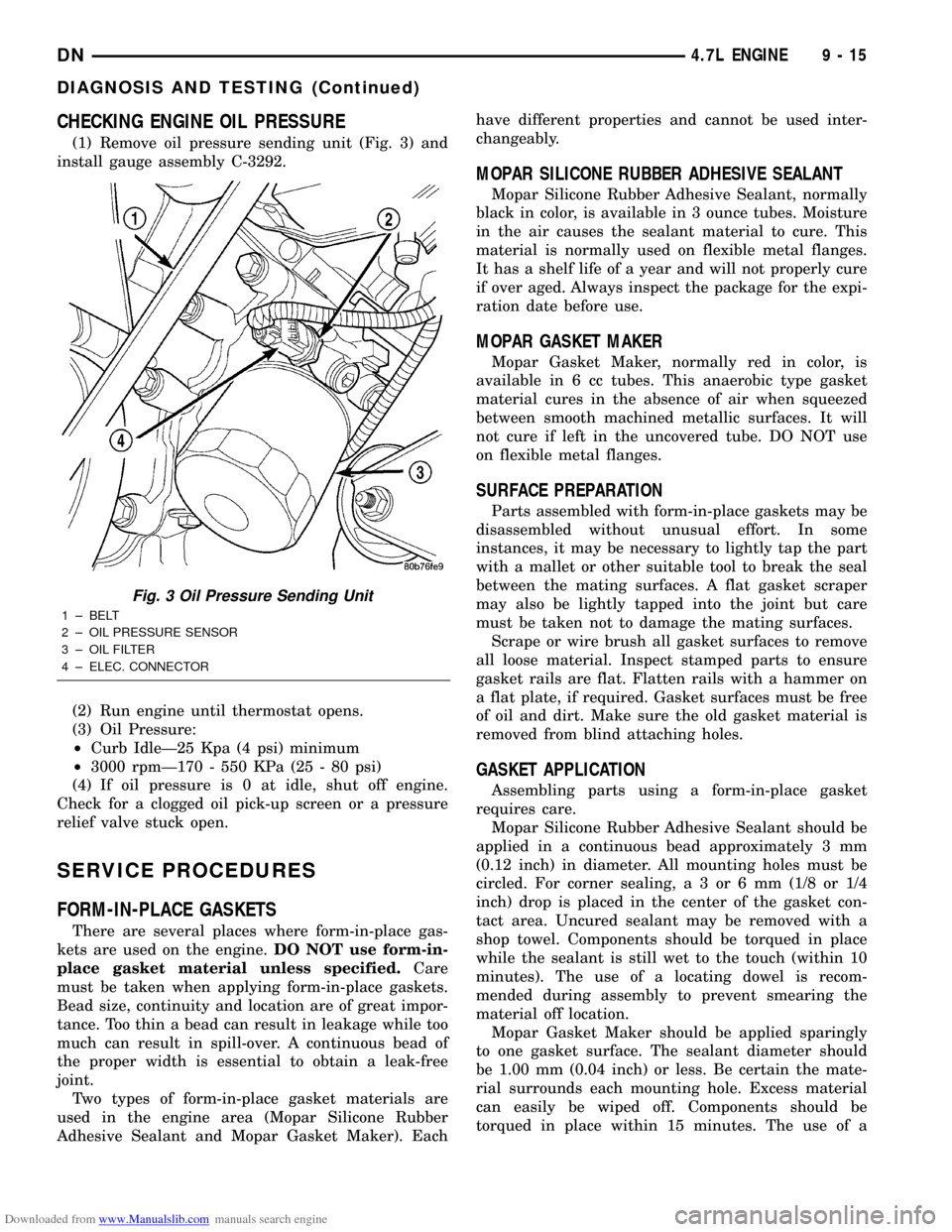
(1) Remove oil pressure sending unit (Fig. 3) and
install gauge assembly C-3292.
(2) Run engine until thermostat opens.
(3) Oil Pressure:
²Curb IdleÐ25 Kpa (4 psi) minimum
²3000 rpmÐ170 - 550 KPa (25 - 80 psi)
(4) If oil pressure is 0 at idle, shut off engine.
Check for a clogged oil pick-up screen or a pressure
relief valve stuck open.
SERVICE PROCEDURES
FORM-IN-PLACE GASKETS
There are several places where form-in-place gas-
kets are used on the engine.DO NOT use form-in-
place gasket material unless specified.Care
must be taken when applying form-in-place gaskets.
Bead size, continuity and location are of great impor-
tance. Too thin a bead can result in leakage while too
much can result in spill-over. A continuous bead of
the proper width is essential to obtain a leak-free
joint.
Two types of form-in-place gasket materials are
used in the engine area (Mopar Silicone Rubber
Adhesive Sealant and Mopar Gasket Maker). Eachhave different properties and cannot be used inter-
changeably.
MOPAR SILICONE RUBBER ADHESIVE SEALANT
Mopar Silicone Rubber Adhesive Sealant, normally
black in color, is available in 3 ounce tubes. Moisture
in the air causes the sealant material to cure. This
material is normally used on flexible metal flanges.
It has a shelf life of a year and will not properly cure
if over aged. Always inspect the package for the expi-
ration date before use.
MOPAR GASKET MAKER
Mopar Gasket Maker, normally red in color, is
available in 6 cc tubes. This anaerobic type gasket
material cures in the absence of air when squeezed
between smooth machined metallic surfaces. It will
not cure if left in the uncovered tube. DO NOT use
on flexible metal flanges.
SURFACE PREPARATION
Parts assembled with form-in-place gaskets may be
disassembled without unusual effort. In some
instances, it may be necessary to lightly tap the part
with a mallet or other suitable tool to break the seal
between the mating surfaces. A flat gasket scraper
may also be lightly tapped into the joint but care
must be taken not to damage the mating surfaces.
Scrape or wire brush all gasket surfaces to remove
all loose material. Inspect stamped parts to ensure
gasket rails are flat. Flatten rails with a hammer on
a flat plate, if required. Gasket surfaces must be free
of oil and dirt. Make sure the old gasket material is
removed from blind attaching holes.
GASKET APPLICATION
Assembling parts using a form-in-place gasket
requires care.
Mopar Silicone Rubber Adhesive Sealant should be
applied in a continuous bead approximately 3 mm
(0.12 inch) in diameter. All mounting holes must be
circled. For corner sealing,a3or6mm(1/8 or 1/4
inch) drop is placed in the center of the gasket con-
tact area. Uncured sealant may be removed with a
shop towel. Components should be torqued in place
while the sealant is still wet to the touch (within 10
minutes). The use of a locating dowel is recom-
mended during assembly to prevent smearing the
material off location.
Mopar Gasket Maker should be applied sparingly
to one gasket surface. The sealant diameter should
be 1.00 mm (0.04 inch) or less. Be certain the mate-
rial surrounds each mounting hole. Excess material
can easily be wiped off. Components should be
torqued in place within 15 minutes. The use of a
Fig. 3 Oil Pressure Sending Unit
1 ± BELT
2 ± OIL PRESSURE SENSOR
3 ± OIL FILTER
4 ± ELEC. CONNECTOR
DN4.7L ENGINE 9 - 15
DIAGNOSIS AND TESTING (Continued)
Page 24 of 193
Downloaded from www.Manualslib.com manuals search engine PISTON RINGSÐFITTING
RING END GAP
Before reinstalling used rings or installing new
rings, the ring clearances must be checked.
(1) Wipe the cylinder bore clean.
(2) Insert the ring in the cylinder bore.
NOTE: The ring gap measurement must be made
with the ring positioned at least 12mm (0.50 inch.)
from bottom of cylinder bore.
(3) Using a piston, to ensure that the ring is
squared in the cylinder bore, slide the ring downward
into the cylinder.
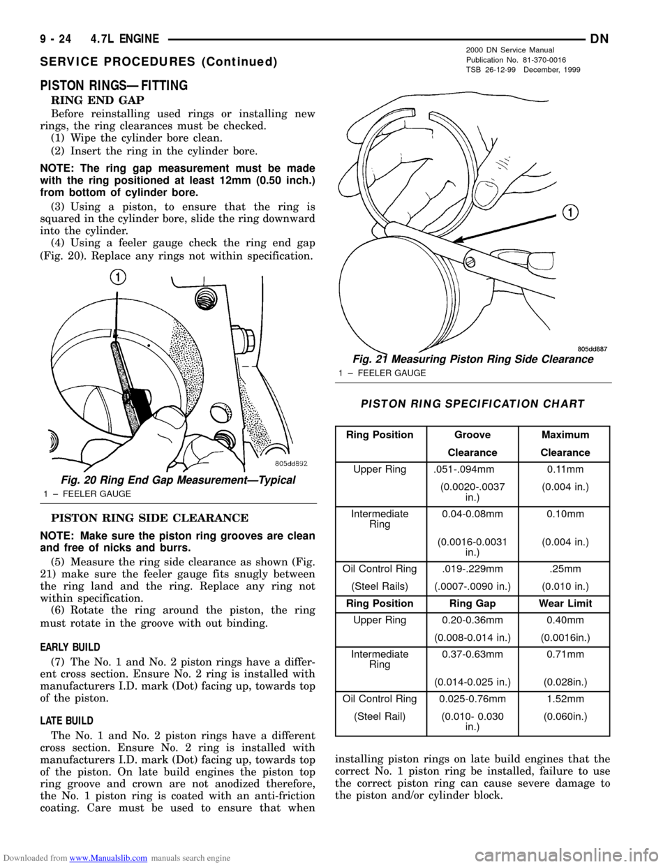
(4) Using a feeler gauge check the ring end gap
(Fig. 20). Replace any rings not within specification.
PISTON RING SIDE CLEARANCE
NOTE: Make sure the piston ring grooves are clean
and free of nicks and burrs.
(5) Measure the ring side clearance as shown (Fig.
21) make sure the feeler gauge fits snugly between
the ring land and the ring. Replace any ring not
within specification.
(6) Rotate the ring around the piston, the ring
must rotate in the groove with out binding.
EARLY BUILD
(7) The No. 1 and No. 2 piston rings have a differ-
ent cross section. Ensure No. 2 ring is installed with
manufacturers I.D. mark (Dot) facing up, towards top
of the piston.
LATE BUILD
The No. 1 and No. 2 piston rings have a different
cross section. Ensure No. 2 ring is installed with
manufacturers I.D. mark (Dot) facing up, towards top
of the piston. On late build engines the piston top
ring groove and crown are not anodized therefore,
the No. 1 piston ring is coated with an anti-friction
coating. Care must be used to ensure that wheninstalling piston rings on late build engines that the
correct No. 1 piston ring be installed, failure to use
the correct piston ring can cause severe damage to
the piston and/or cylinder block.
Fig. 20 Ring End Gap MeasurementÐTypical
1 ± FEELER GAUGE
Fig. 21 Measuring Piston Ring Side Clearance
1 ± FEELER GAUGE
PISTON RING SPECIFICATION CHART
Ring Position Groove Maximum
Clearance Clearance
Upper Ring .051-.094mm 0.11mm
(0.0020-.0037
in.)(0.004 in.)
Intermediate
Ring0.04-0.08mm 0.10mm
(0.0016-0.0031
in.)(0.004 in.)
Oil Control Ring .019-.229mm .25mm
(Steel Rails) (.0007-.0090 in.) (0.010 in.)
Ring Position Ring Gap Wear Limit
Upper Ring 0.20-0.36mm 0.40mm
(0.008-0.014 in.) (0.0016in.)
Intermediate
Ring0.37-0.63mm 0.71mm
(0.014-0.025 in.) (0.028in.)
Oil Control Ring 0.025-0.76mm 1.52mm
(Steel Rail) (0.010- 0.030
in.)(0.060in.)
9 - 24 4.7L ENGINEDN
SERVICE PROCEDURES (Continued)
2000 DN Service Manual
Publication No. 81-370-0016
TSB 26-12-99 December, 1999
Page 64 of 193
Downloaded from www.Manualslib.com manuals search engine (5) Lower engine and install both the left and
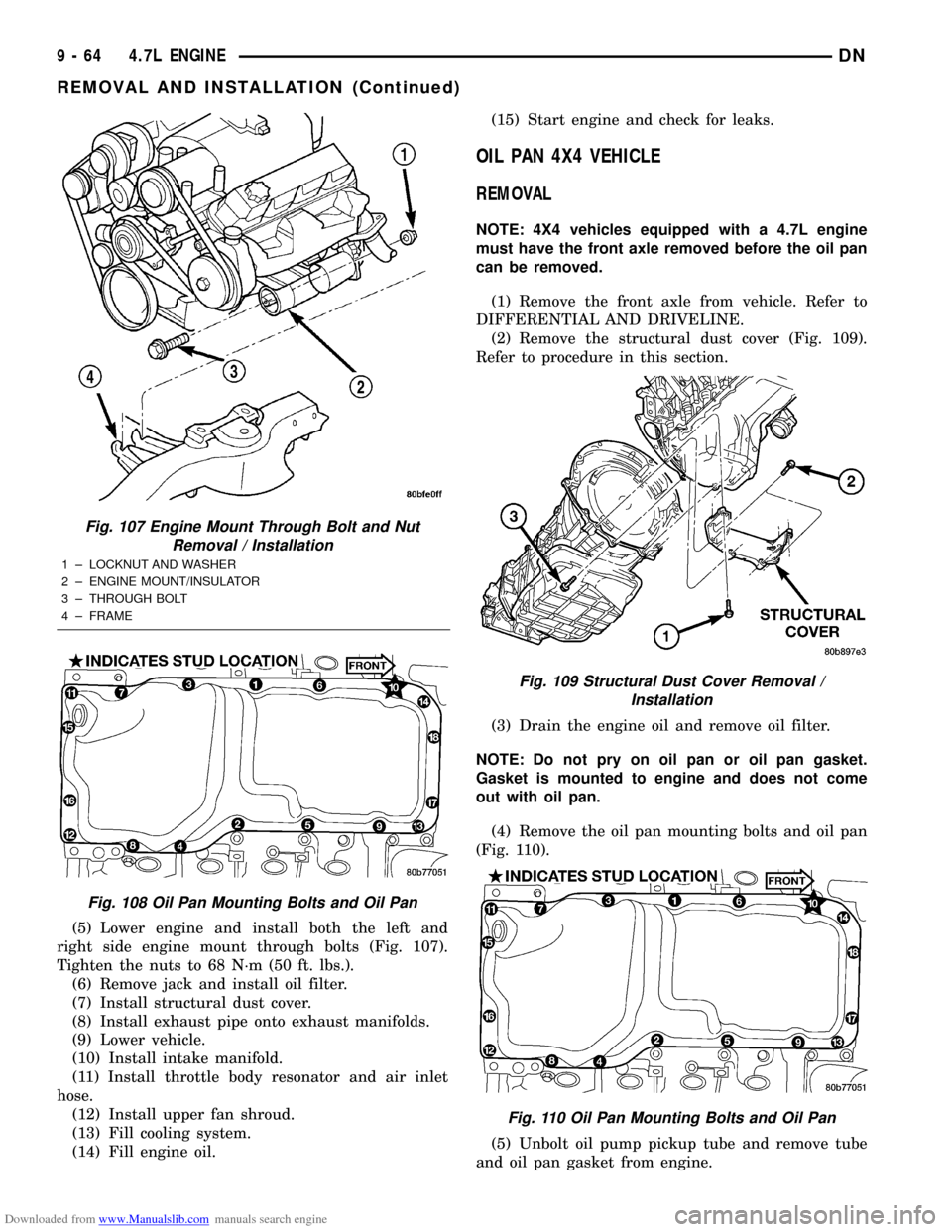
right side engine mount through bolts (Fig. 107).
Tighten the nuts to 68 N´m (50 ft. lbs.).
(6) Remove jack and install oil filter.
(7) Install structural dust cover.
(8) Install exhaust pipe onto exhaust manifolds.
(9) Lower vehicle.
(10) Install intake manifold.
(11) Install throttle body resonator and air inlet
hose.
(12) Install upper fan shroud.
(13) Fill cooling system.
(14) Fill engine oil.(15) Start engine and check for leaks.
OIL PAN 4X4 VEHICLE
REMOVAL
NOTE: 4X4 vehicles equipped with a 4.7L engine
must have the front axle removed before the oil pan
can be removed.
(1) Remove the front axle from vehicle. Refer to
DIFFERENTIAL AND DRIVELINE.
(2) Remove the structural dust cover (Fig. 109).
Refer to procedure in this section.
(3) Drain the engine oil and remove oil filter.
NOTE: Do not pry on oil pan or oil pan gasket.
Gasket is mounted to engine and does not come
out with oil pan.
(4) Remove the oil pan mounting bolts and oil pan
(Fig. 110).
(5) Unbolt oil pump pickup tube and remove tube
and oil pan gasket from engine.
Fig. 107 Engine Mount Through Bolt and Nut
Removal / Installation
1 ± LOCKNUT AND WASHER
2 ± ENGINE MOUNT/INSULATOR
3 ± THROUGH BOLT
4 ± FRAME
Fig. 108 Oil Pan Mounting Bolts and Oil Pan
Fig. 109 Structural Dust Cover Removal /
Installation
Fig. 110 Oil Pan Mounting Bolts and Oil Pan
9 - 64 4.7L ENGINEDN
REMOVAL AND INSTALLATION (Continued)
Page 65 of 193
Downloaded from www.Manualslib.com manuals search engine INSTALLATION
(1) Clean the oil pan gasket mating surface of the
bedplate and oil pan.
(2) Position the oil pan gasket and pickup tube
with new o-ring. Install the mounting bolt and nuts.
Tighten bolt and nuts to 28 N´m (20 ft. lbs.).
(3) Position the oil pan and install the mounting
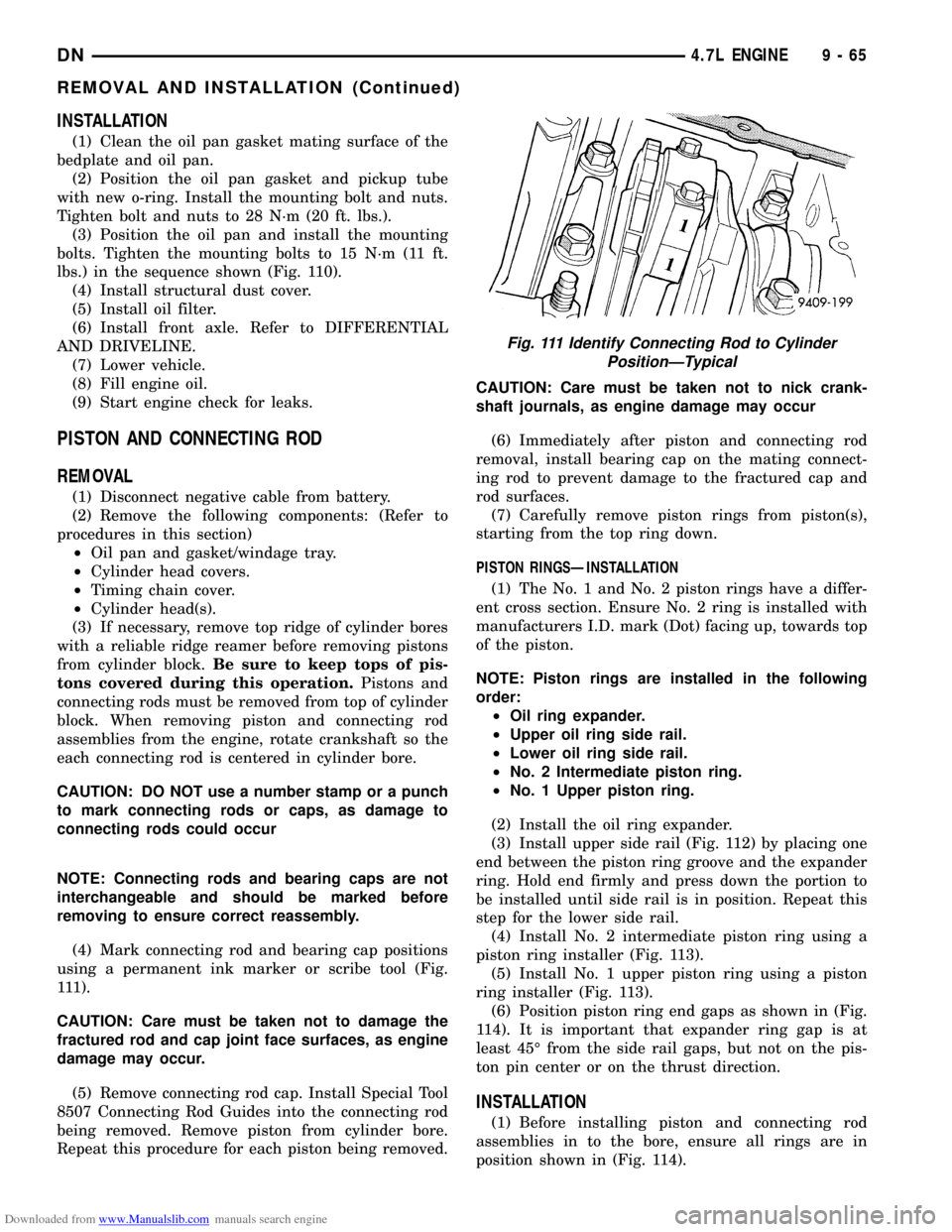
bolts. Tighten the mounting bolts to 15 N´m (11 ft.
lbs.) in the sequence shown (Fig. 110).
(4) Install structural dust cover.
(5) Install oil filter.
(6) Install front axle. Refer to DIFFERENTIAL
AND DRIVELINE.
(7) Lower vehicle.
(8) Fill engine oil.
(9) Start engine check for leaks.
PISTON AND CONNECTING ROD
REMOVAL
(1) Disconnect negative cable from battery.
(2) Remove the following components: (Refer to
procedures in this section)
²Oil pan and gasket/windage tray.
²Cylinder head covers.
²Timing chain cover.
²Cylinder head(s).
(3) If necessary, remove top ridge of cylinder bores
with a reliable ridge reamer before removing pistons
from cylinder block.Be sure to keep tops of pis-
tons covered during this operation.Pistons and
connecting rods must be removed from top of cylinder
block. When removing piston and connecting rod
assemblies from the engine, rotate crankshaft so the
each connecting rod is centered in cylinder bore.
CAUTION: DO NOT use a number stamp or a punch
to mark connecting rods or caps, as damage to
connecting rods could occur
NOTE: Connecting rods and bearing caps are not
interchangeable and should be marked before
removing to ensure correct reassembly.
(4) Mark connecting rod and bearing cap positions
using a permanent ink marker or scribe tool (Fig.
111).
CAUTION: Care must be taken not to damage the
fractured rod and cap joint face surfaces, as engine
damage may occur.
(5) Remove connecting rod cap. Install Special Tool
8507 Connecting Rod Guides into the connecting rod
being removed. Remove piston from cylinder bore.
Repeat this procedure for each piston being removed.CAUTION: Care must be taken not to nick crank-
shaft journals, as engine damage may occur
(6) Immediately after piston and connecting rod
removal, install bearing cap on the mating connect-
ing rod to prevent damage to the fractured cap and
rod surfaces.
(7) Carefully remove piston rings from piston(s),
starting from the top ring down.
PISTON RINGSÐINSTALLATION
(1) The No. 1 and No. 2 piston rings have a differ-
ent cross section. Ensure No. 2 ring is installed with
manufacturers I.D. mark (Dot) facing up, towards top
of the piston.
NOTE: Piston rings are installed in the following
order:
²Oil ring expander.
²Upper oil ring side rail.
²Lower oil ring side rail.
²No. 2 Intermediate piston ring.
²No. 1 Upper piston ring.
(2) Install the oil ring expander.
(3) Install upper side rail (Fig. 112) by placing one
end between the piston ring groove and the expander
ring. Hold end firmly and press down the portion to
be installed until side rail is in position. Repeat this
step for the lower side rail.
(4) Install No. 2 intermediate piston ring using a
piston ring installer (Fig. 113).
(5) Install No. 1 upper piston ring using a piston
ring installer (Fig. 113).
(6) Position piston ring end gaps as shown in (Fig.
114). It is important that expander ring gap is at
least 45É from the side rail gaps, but not on the pis-
ton pin center or on the thrust direction.
INSTALLATION
(1) Before installing piston and connecting rod
assemblies in to the bore, ensure all rings are in
position shown in (Fig. 114).
Fig. 111 Identify Connecting Rod to Cylinder
PositionÐTypical
DN4.7L ENGINE 9 - 65
REMOVAL AND INSTALLATION (Continued)
Page 78 of 193
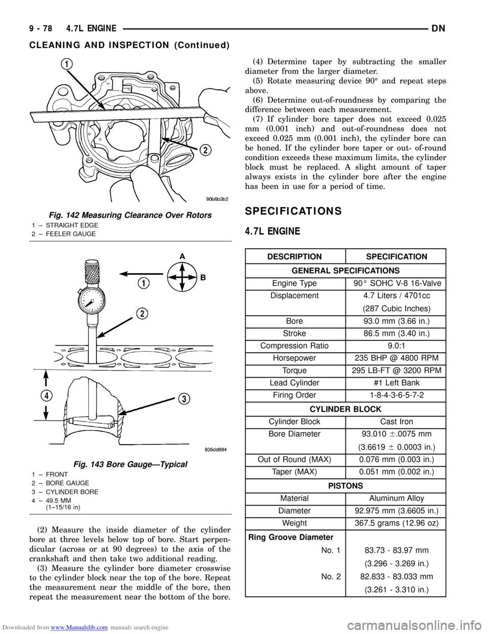
Downloaded from www.Manualslib.com manuals search engine (2) Measure the inside diameter of the cylinder
bore at three levels below top of bore. Start perpen-
dicular (across or at 90 degrees) to the axis of the
crankshaft and then take two additional reading.
(3) Measure the cylinder bore diameter crosswise
to the cylinder block near the top of the bore. Repeat
the measurement near the middle of the bore, then
repeat the measurement near the bottom of the bore.(4) Determine taper by subtracting the smaller
diameter from the larger diameter.
(5) Rotate measuring device 90É and repeat steps
above.
(6) Determine out-of-roundness by comparing the
difference between each measurement.
(7) If cylinder bore taper does not exceed 0.025
mm (0.001 inch) and out-of-roundness does not
exceed 0.025 mm (0.001 inch), the cylinder bore can
be honed. If the cylinder bore taper or out- of-round
condition exceeds these maximum limits, the cylinder
block must be replaced. A slight amount of taper
always exists in the cylinder bore after the engine
has been in use for a period of time.
SPECIFICATIONS
4.7L ENGINE
DESCRIPTION SPECIFICATION
GENERAL SPECIFICATIONS
Engine Type 90É SOHC V-8 16-Valve
Displacement 4.7 Liters / 4701cc
(287 Cubic Inches)
Bore 93.0 mm (3.66 in.)
Stroke 86.5 mm (3.40 in.)
Compression Ratio 9.0:1
Horsepower 235 BHP @ 4800 RPM
Torque 295 LB-FT @ 3200 RPM
Lead Cylinder #1 Left Bank
Firing Order 1-8-4-3-6-5-7-2
CYLINDER BLOCK
Cylinder Block Cast Iron
Bore Diameter 93.0106.0075 mm
(3.661960.0003 in.)
Out of Round (MAX) 0.076 mm (0.003 in.)
Taper (MAX) 0.051 mm (0.002 in.)
PISTONS
Material Aluminum Alloy
Diameter 92.975 mm (3.6605 in.)
Weight 367.5 grams (12.96 oz)
Ring Groove Diameter
No. 1 83.73 - 83.97 mm
(3.296 - 3.269 in.)
No. 2 82.833 - 83.033 mm
(3.261 - 3.310 in.)
Fig. 142 Measuring Clearance Over Rotors
1 ± STRAIGHT EDGE
2 ± FEELER GAUGE
Fig. 143 Bore GaugeÐTypical
1 ± FRONT
2 ± BORE GAUGE
3 ± CYLINDER BORE
4 ± 49.5 MM
(1±15/16 in)
9 - 78 4.7L ENGINEDN
CLEANING AND INSPECTION (Continued)
Page 91 of 193
Downloaded from www.Manualslib.com manuals search engine CRANKSHAFT MAIN BEARINGS
DESCRIPTION
Main bearings are located in the cylinder block.
One half of the main bearing is located in the crank-
shaft main bore the other half of the matching bear-
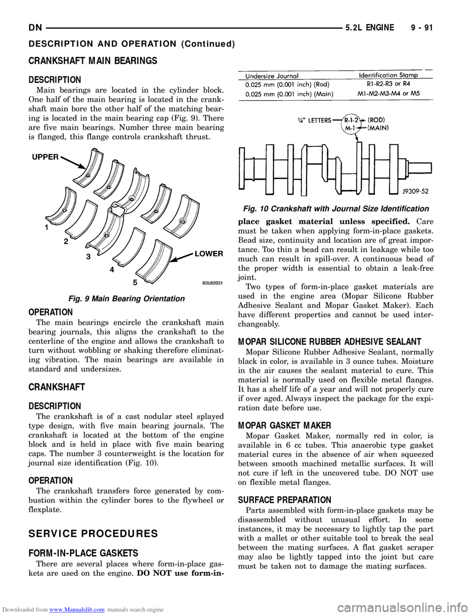
ing is located in the main bearing cap (Fig. 9). There
are five main bearings. Number three main bearing
is flanged, this flange controls crankshaft thrust.
OPERATION
The main bearings encircle the crankshaft main
bearing journals, this aligns the crankshaft to the
centerline of the engine and allows the crankshaft to
turn without wobbling or shaking therefore eliminat-
ing vibration. The main bearings are available in
standard and undersizes.
CRANKSHAFT
DESCRIPTION
The crankshaft is of a cast nodular steel splayed
type design, with five main bearing journals. The
crankshaft is located at the bottom of the engine
block and is held in place with five main bearing
caps. The number 3 counterweight is the location for
journal size identification (Fig. 10).
OPERATION
The crankshaft transfers force generated by com-
bustion within the cylinder bores to the flywheel or
flexplate.
SERVICE PROCEDURES
FORM-IN-PLACE GASKETS
There are several places where form-in-place gas-
kets are used on the engine.DO NOT use form-in-place gasket material unless specified.Care
must be taken when applying form-in-place gaskets.
Bead size, continuity and location are of great impor-
tance. Too thin a bead can result in leakage while too
much can result in spill-over. A continuous bead of
the proper width is essential to obtain a leak-free
joint.
Two types of form-in-place gasket materials are
used in the engine area (Mopar Silicone Rubber
Adhesive Sealant and Mopar Gasket Maker). Each
have different properties and cannot be used inter-
changeably.
MOPAR SILICONE RUBBER ADHESIVE SEALANT
Mopar Silicone Rubber Adhesive Sealant, normally
black in color, is available in 3 ounce tubes. Moisture
in the air causes the sealant material to cure. This
material is normally used on flexible metal flanges.
It has a shelf life of a year and will not properly cure
if over aged. Always inspect the package for the expi-
ration date before use.
MOPAR GASKET MAKER
Mopar Gasket Maker, normally red in color, is
available in 6 cc tubes. This anaerobic type gasket
material cures in the absence of air when squeezed
between smooth machined metallic surfaces. It will
not cure if left in the uncovered tube. DO NOT use
on flexible metal flanges.
SURFACE PREPARATION
Parts assembled with form-in-place gaskets may be
disassembled without unusual effort. In some
instances, it may be necessary to lightly tap the part
with a mallet or other suitable tool to break the seal
between the mating surfaces. A flat gasket scraper
may also be lightly tapped into the joint but care
must be taken not to damage the mating surfaces.
Fig. 9 Main Bearing Orientation
Fig. 10 Crankshaft with Journal Size Identification
DN5.2L ENGINE 9 - 91
DESCRIPTION AND OPERATION (Continued)
Page 101 of 193
Downloaded from www.Manualslib.com manuals search engine (1) Disconnect the negative cable from the battery.
(2) Raise vehicle on hoist.
(3) Install engine lifting (support) fixture.
(4) Remove front axle assembly. (Refer to Group 3,
Differential and Driveline in this publication.)
(5)Left mount insulator only.Remove starter
wires and starter motor assembly.
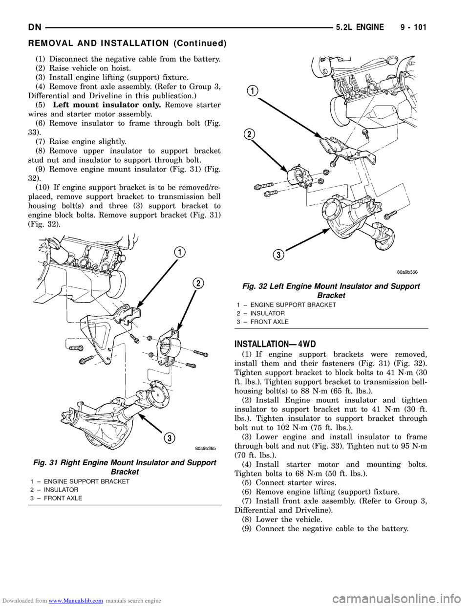
(6) Remove insulator to frame through bolt (Fig.
33).
(7) Raise engine slightly.
(8) Remove upper insulator to support bracket
stud nut and insulator to support through bolt.
(9) Remove engine mount insulator (Fig. 31) (Fig.
32).
(10) If engine support bracket is to be removed/re-
placed, remove support bracket to transmission bell
housing bolt(s) and three (3) support bracket to
engine block bolts. Remove support bracket (Fig. 31)
(Fig. 32).
INSTALLATIONÐ4WD
(1) If engine support brackets were removed,
install them and their fasteners (Fig. 31) (Fig. 32).
Tighten support bracket to block bolts to 41 N´m (30
ft. lbs.). Tighten support bracket to transmission bell-
housing bolt(s) to 88 N´m (65 ft. lbs.).
(2) Install Engine mount insulator and tighten
insulator to support bracket nut to 41 N´m (30 ft.
lbs.). Tighten insulator to support bracket through
bolt nut to 102 N´m (75 ft. lbs.).
(3) Lower engine and install insulator to frame
through bolt and nut (Fig. 33). Tighten nut to 95 N´m
(70 ft. lbs.).
(4) Install starter motor and mounting bolts.
Tighten bolts to 68 N´m (50 ft. lbs.).
(5) Connect starter wires.
(6) Remove engine lifting (support) fixture.
(7) Install front axle assembly. (Refer to Group 3,
Differential and Driveline).
(8) Lower the vehicle.
(9) Connect the negative cable to the battery.
Fig. 31 Right Engine Mount Insulator and Support
Bracket
1 ± ENGINE SUPPORT BRACKET
2 ± INSULATOR
3 ± FRONT AXLE
Fig. 32 Left Engine Mount Insulator and Support
Bracket
1 ± ENGINE SUPPORT BRACKET
2 ± INSULATOR
3 ± FRONT AXLE
DN5.2L ENGINE 9 - 101
REMOVAL AND INSTALLATION (Continued)