Shaft DODGE DURANGO 2000 1.G Repair Manual
[x] Cancel search | Manufacturer: DODGE, Model Year: 2000, Model line: DURANGO, Model: DODGE DURANGO 2000 1.GPages: 193, PDF Size: 5.65 MB
Page 67 of 193
Downloaded from www.Manualslib.com manuals search engine (7) Rotate crankshaft until connecting rod journal
is on the center of cylinder bore. Insert rod and pis-
ton into cylinder bore and carefully position connect-
ing rod guides over crankshaft journal.
(8) Tap piston down in cylinder bore using a ham-
mer handle. While at the same time, guide connect-
ing rod into position on rod journal.
CAUTION: Connecting Rod Bolts are Torque to
Yield Bolts and Must Not Be Reused. Always
replace the Rod Bolts whenever they are loosened
or removed.
(9) Lubricate rod bolts and bearing surfaces with
engine oil. Install connecting rod cap and bearing.
Tighten bolts to 27 N´m (20 ft. lbs.) plus 90É.
(10) Install the following components: (Refer to
procedures in this section)
²Cylinder head(s).
²Timing chain and cover.
²Cylinder head covers.
²Oil pan and gasket/windage tray.
(11) Fill crankcase with proper engine oil to cor-
rect level.
(12) Connect negative cable to battery.
CRANKSHAFT
REMOVAL
NOTE: To remove the crankshaft from the engine,
the engine must be removed from the vehicle.
(1) Remove the engine. Refer to Engine Assembly
in this section for procedure.
(2) Remove the engine oil pump. Refer to Oil
Pump in this section for procedure.
CAUTION: DO NOT pry on the oil pan gasket when
removing the oil pan, The oil pan gasket is mounted
to the cylinder block in three locations and will
remain attached to block when removing oil pan.
Gasket can not be removed with oil pan.
(3) Remove oil pan bolts and oil pan.
(4) Remove the oil pump pickup tube and oil pan
gasket /windage tray.
(5) Remove the bedplate mounting bolts. Note the
location of the three stud bolts for installation.
(6) Remove the connecting rods from the crank-
shaft.
CAUTION: The bedplate to cylinder block mating
surface is a critical sealing surface. Do not pry on
or damage this surface in anyway.
NOTE: The bedplate contains the lower main bear-
ing halves. Use care when handling bedplate as not
to drop or damage bearing halves. Installing main
bearing halves in the wrong position will cause
sever damage to the crankshaft.
NOTE: The bedplate has pry points cast into it. Use
these points only. The pry points are on both the
left and right sides, only the left side is shown.
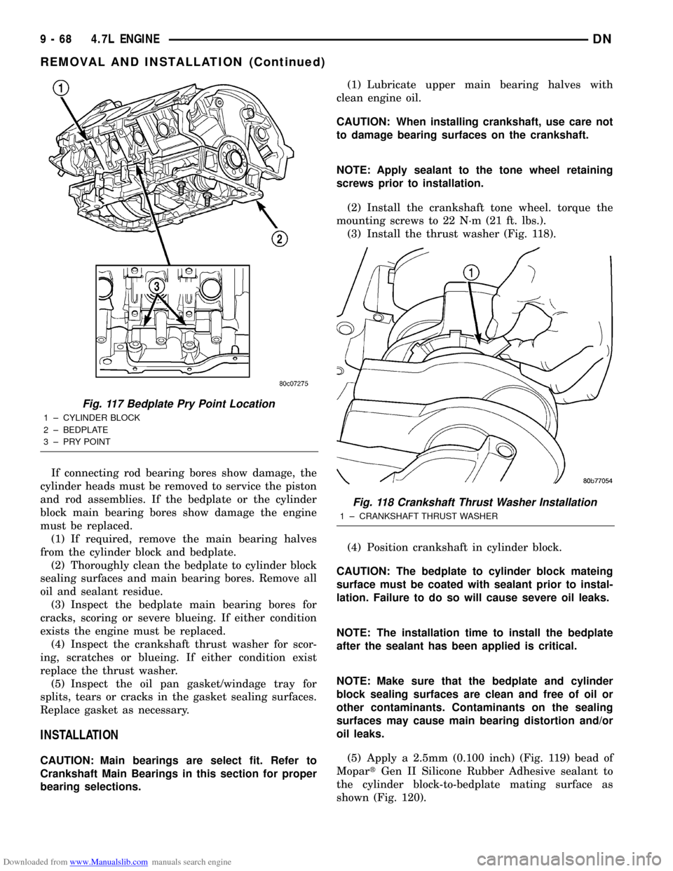
(7) Carefully pry on the pry points (Fig. 117) to
loosen the bedplate then remove the bedplate.
CAUTION: When removing the crankshaft, use care
not to damage bearing surfaces on the crankshaft.
(8) Remove the crankshaft.
(9) Remove the crankshaft tone wheel.
INSPECTION
NOTE: Thoroughly inspect the connecting rod
bearing bores and main bearing bores for scoring,
blueing or severe scratches. Further disassembly
may be required.
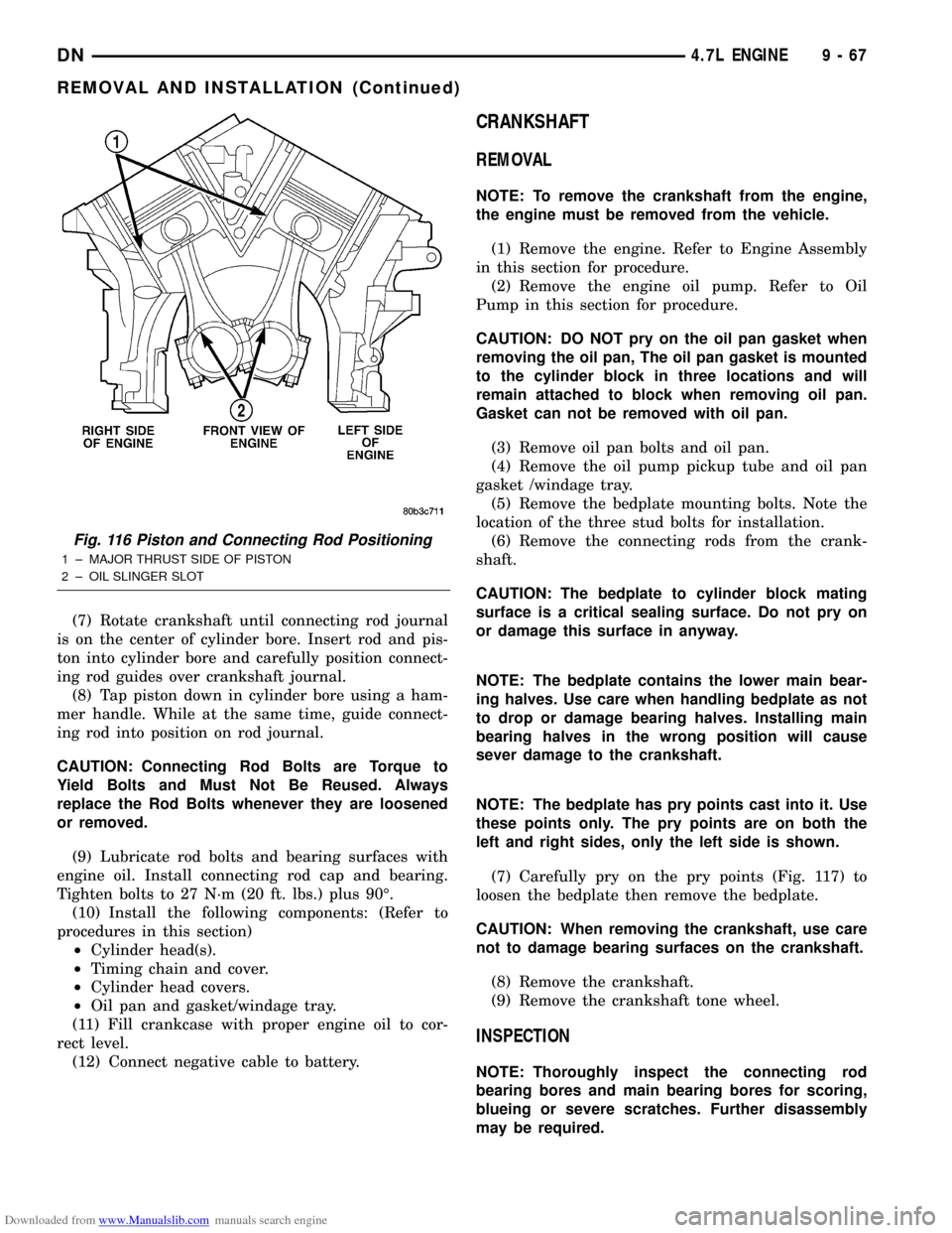
Fig. 116 Piston and Connecting Rod Positioning
1 ± MAJOR THRUST SIDE OF PISTON
2 ± OIL SLINGER SLOT
DN4.7L ENGINE 9 - 67
REMOVAL AND INSTALLATION (Continued)
Page 68 of 193
Downloaded from www.Manualslib.com manuals search engine If connecting rod bearing bores show damage, the
cylinder heads must be removed to service the piston
and rod assemblies. If the bedplate or the cylinder
block main bearing bores show damage the engine
must be replaced.
(1) If required, remove the main bearing halves
from the cylinder block and bedplate.
(2) Thoroughly clean the bedplate to cylinder block
sealing surfaces and main bearing bores. Remove all
oil and sealant residue.
(3) Inspect the bedplate main bearing bores for
cracks, scoring or severe blueing. If either condition
exists the engine must be replaced.
(4) Inspect the crankshaft thrust washer for scor-
ing, scratches or blueing. If either condition exist
replace the thrust washer.
(5) Inspect the oil pan gasket/windage tray for
splits, tears or cracks in the gasket sealing surfaces.
Replace gasket as necessary.
INSTALLATION
CAUTION: Main bearings are select fit. Refer to
Crankshaft Main Bearings in this section for proper
bearing selections.(1) Lubricate upper main bearing halves with
clean engine oil.
CAUTION: When installing crankshaft, use care not
to damage bearing surfaces on the crankshaft.
NOTE: Apply sealant to the tone wheel retaining
screws prior to installation.
(2) Install the crankshaft tone wheel. torque the
mounting screws to 22 N´m (21 ft. lbs.).
(3) Install the thrust washer (Fig. 118).
(4) Position crankshaft in cylinder block.
CAUTION: The bedplate to cylinder block mateing
surface must be coated with sealant prior to instal-
lation. Failure to do so will cause severe oil leaks.
NOTE: The installation time to install the bedplate
after the sealant has been applied is critical.
NOTE: Make sure that the bedplate and cylinder
block sealing surfaces are clean and free of oil or
other contaminants. Contaminants on the sealing
surfaces may cause main bearing distortion and/or
oil leaks.
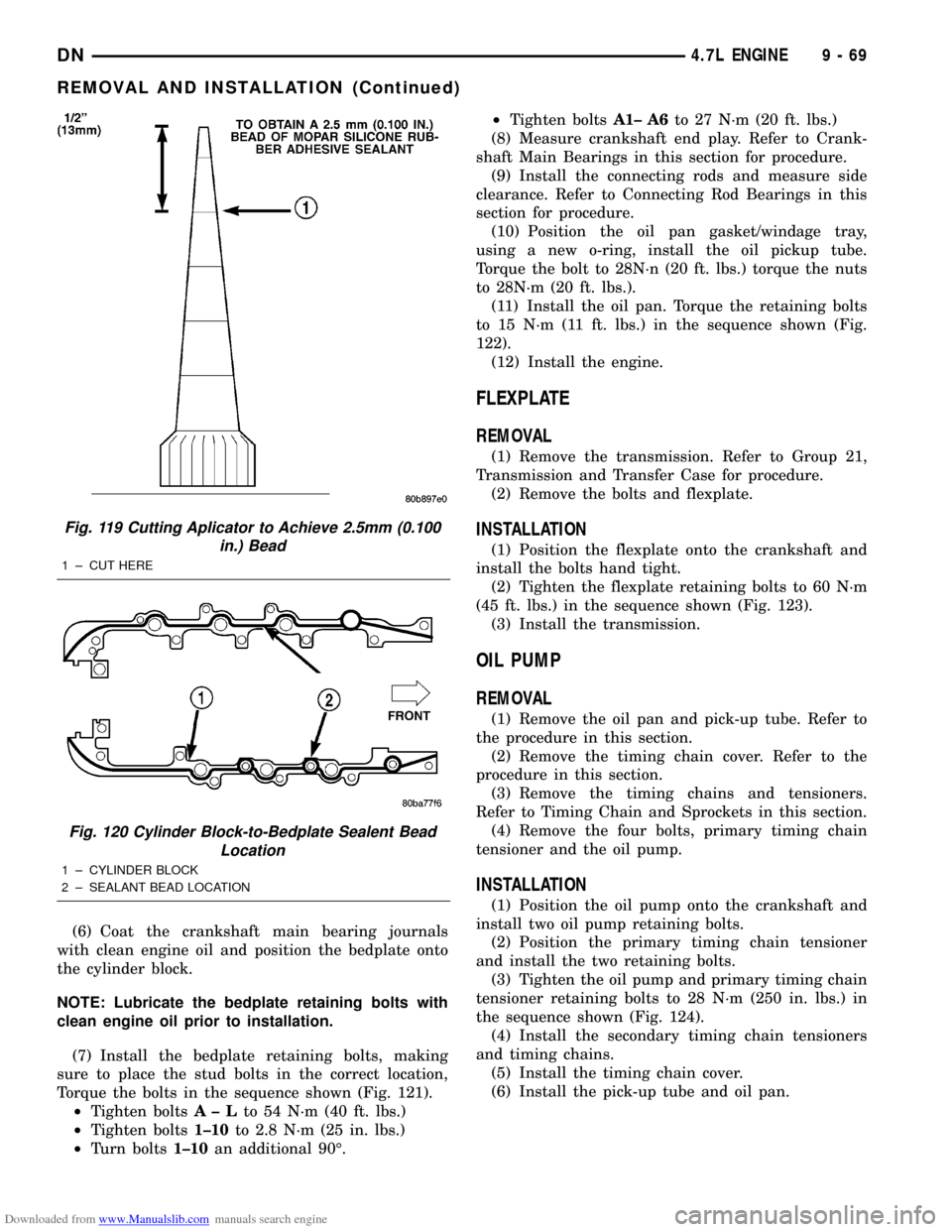
(5) Apply a 2.5mm (0.100 inch) (Fig. 119) bead of
MopartGen II Silicone Rubber Adhesive sealant to
the cylinder block-to-bedplate mating surface as
shown (Fig. 120).
Fig. 117 Bedplate Pry Point Location
1 ± CYLINDER BLOCK
2 ± BEDPLATE
3 ± PRY POINT
Fig. 118 Crankshaft Thrust Washer Installation
1 ± CRANKSHAFT THRUST WASHER
9 - 68 4.7L ENGINEDN
REMOVAL AND INSTALLATION (Continued)
Page 69 of 193
Downloaded from www.Manualslib.com manuals search engine (6) Coat the crankshaft main bearing journals
with clean engine oil and position the bedplate onto
the cylinder block.
NOTE: Lubricate the bedplate retaining bolts with
clean engine oil prior to installation.
(7) Install the bedplate retaining bolts, making
sure to place the stud bolts in the correct location,
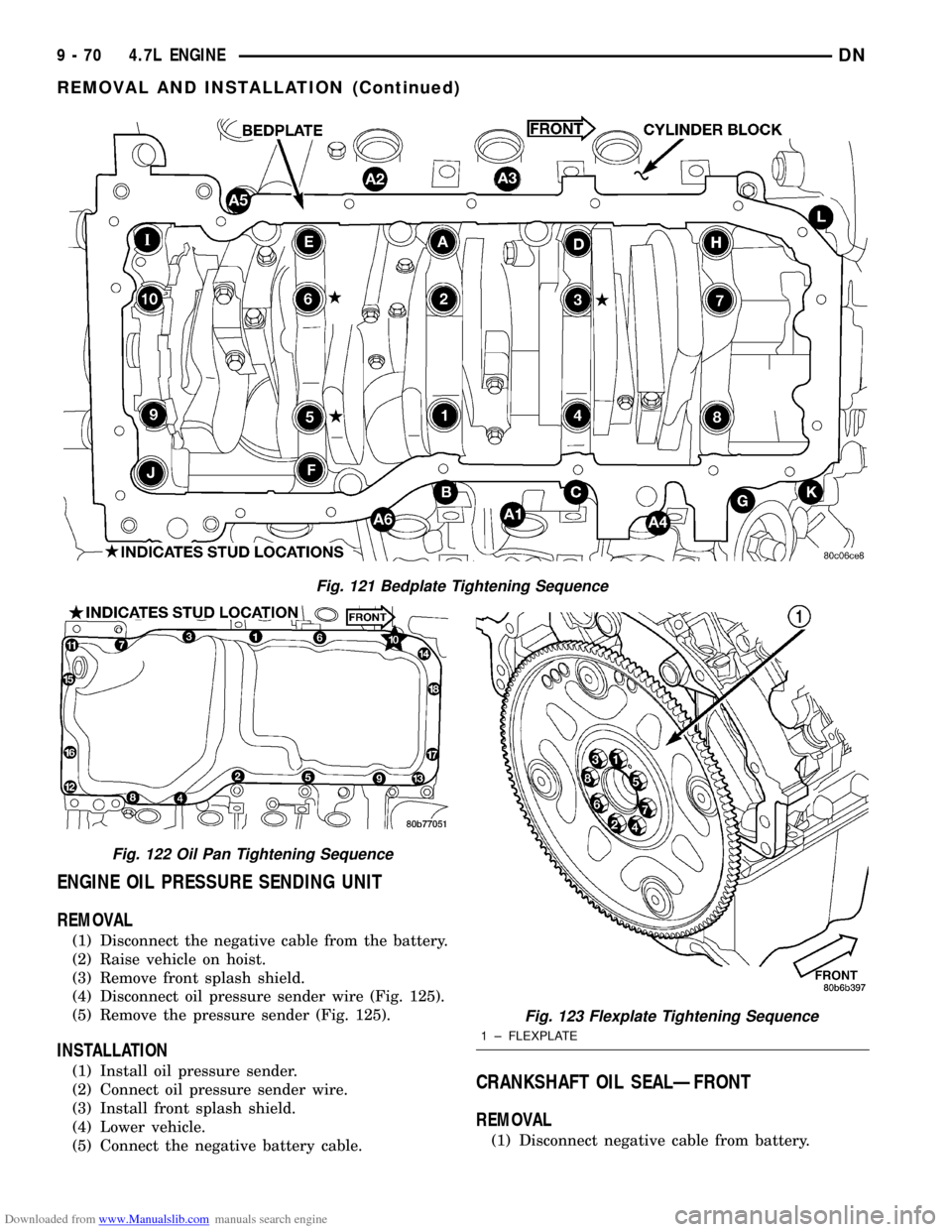
Torque the bolts in the sequence shown (Fig. 121).
²Tighten boltsA± Lto 54 N´m (40 ft. lbs.)
²Tighten bolts1±10to 2.8 N´m (25 in. lbs.)
²Turn bolts1±10an additional 90É.²Tighten boltsA1± A6to 27 N´m (20 ft. lbs.)
(8) Measure crankshaft end play. Refer to Crank-
shaft Main Bearings in this section for procedure.
(9) Install the connecting rods and measure side
clearance. Refer to Connecting Rod Bearings in this
section for procedure.
(10) Position the oil pan gasket/windage tray,
using a new o-ring, install the oil pickup tube.
Torque the bolt to 28N´n (20 ft. lbs.) torque the nuts
to 28N´m (20 ft. lbs.).
(11) Install the oil pan. Torque the retaining bolts
to 15 N´m (11 ft. lbs.) in the sequence shown (Fig.
122).
(12) Install the engine.
FLEXPLATE
REMOVAL
(1) Remove the transmission. Refer to Group 21,
Transmission and Transfer Case for procedure.
(2) Remove the bolts and flexplate.
INSTALLATION
(1) Position the flexplate onto the crankshaft and
install the bolts hand tight.
(2) Tighten the flexplate retaining bolts to 60 N´m
(45 ft. lbs.) in the sequence shown (Fig. 123).
(3) Install the transmission.
OIL PUMP
REMOVAL
(1) Remove the oil pan and pick-up tube. Refer to
the procedure in this section.
(2) Remove the timing chain cover. Refer to the
procedure in this section.
(3) Remove the timing chains and tensioners.
Refer to Timing Chain and Sprockets in this section.
(4) Remove the four bolts, primary timing chain
tensioner and the oil pump.
INSTALLATION
(1) Position the oil pump onto the crankshaft and
install two oil pump retaining bolts.
(2) Position the primary timing chain tensioner
and install the two retaining bolts.
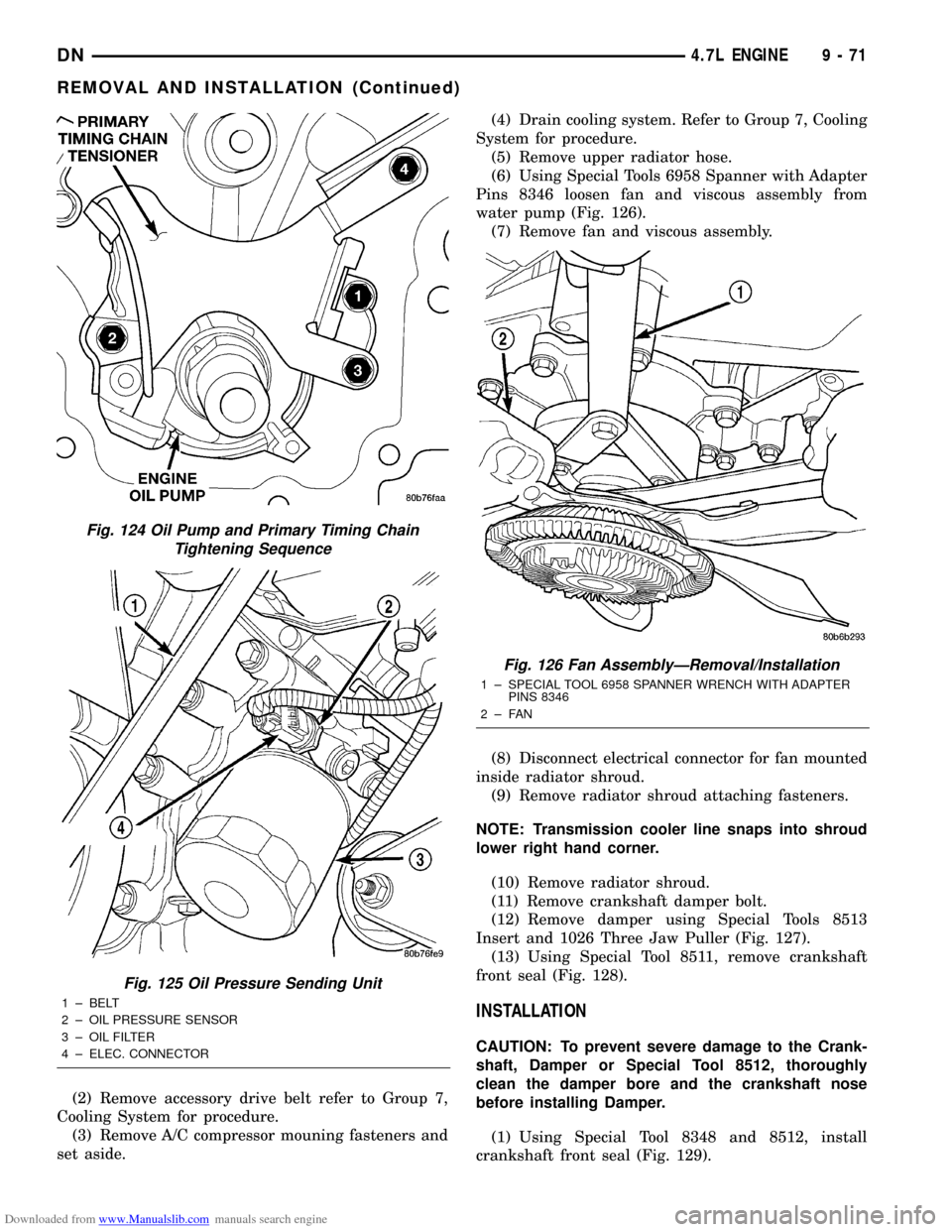
(3) Tighten the oil pump and primary timing chain
tensioner retaining bolts to 28 N´m (250 in. lbs.) in
the sequence shown (Fig. 124).
(4) Install the secondary timing chain tensioners
and timing chains.
(5) Install the timing chain cover.
(6) Install the pick-up tube and oil pan.
Fig. 119 Cutting Aplicator to Achieve 2.5mm (0.100
in.) Bead
1 ± CUT HERE
Fig. 120 Cylinder Block-to-Bedplate Sealent Bead
Location
1 ± CYLINDER BLOCK
2 ± SEALANT BEAD LOCATION
DN4.7L ENGINE 9 - 69
REMOVAL AND INSTALLATION (Continued)
Page 70 of 193
Downloaded from www.Manualslib.com manuals search engine ENGINE OIL PRESSURE SENDING UNIT
REMOVAL
(1) Disconnect the negative cable from the battery.
(2) Raise vehicle on hoist.
(3) Remove front splash shield.
(4) Disconnect oil pressure sender wire (Fig. 125).
(5) Remove the pressure sender (Fig. 125).
INSTALLATION
(1) Install oil pressure sender.
(2) Connect oil pressure sender wire.
(3) Install front splash shield.
(4) Lower vehicle.
(5) Connect the negative battery cable.CRANKSHAFT OIL SEALÐFRONT
REMOVAL
(1) Disconnect negative cable from battery.
Fig. 121 Bedplate Tightening Sequence
Fig. 122 Oil Pan Tightening Sequence
Fig. 123 Flexplate Tightening Sequence
1 ± FLEXPLATE
9 - 70 4.7L ENGINEDN
REMOVAL AND INSTALLATION (Continued)
Page 71 of 193
Downloaded from www.Manualslib.com manuals search engine (2) Remove accessory drive belt refer to Group 7,
Cooling System for procedure.
(3) Remove A/C compressor mouning fasteners and
set aside.(4) Drain cooling system. Refer to Group 7, Cooling
System for procedure.
(5) Remove upper radiator hose.
(6) Using Special Tools 6958 Spanner with Adapter
Pins 8346 loosen fan and viscous assembly from
water pump (Fig. 126).
(7) Remove fan and viscous assembly.
(8) Disconnect electrical connector for fan mounted
inside radiator shroud.
(9) Remove radiator shroud attaching fasteners.
NOTE: Transmission cooler line snaps into shroud
lower right hand corner.
(10) Remove radiator shroud.
(11) Remove crankshaft damper bolt.
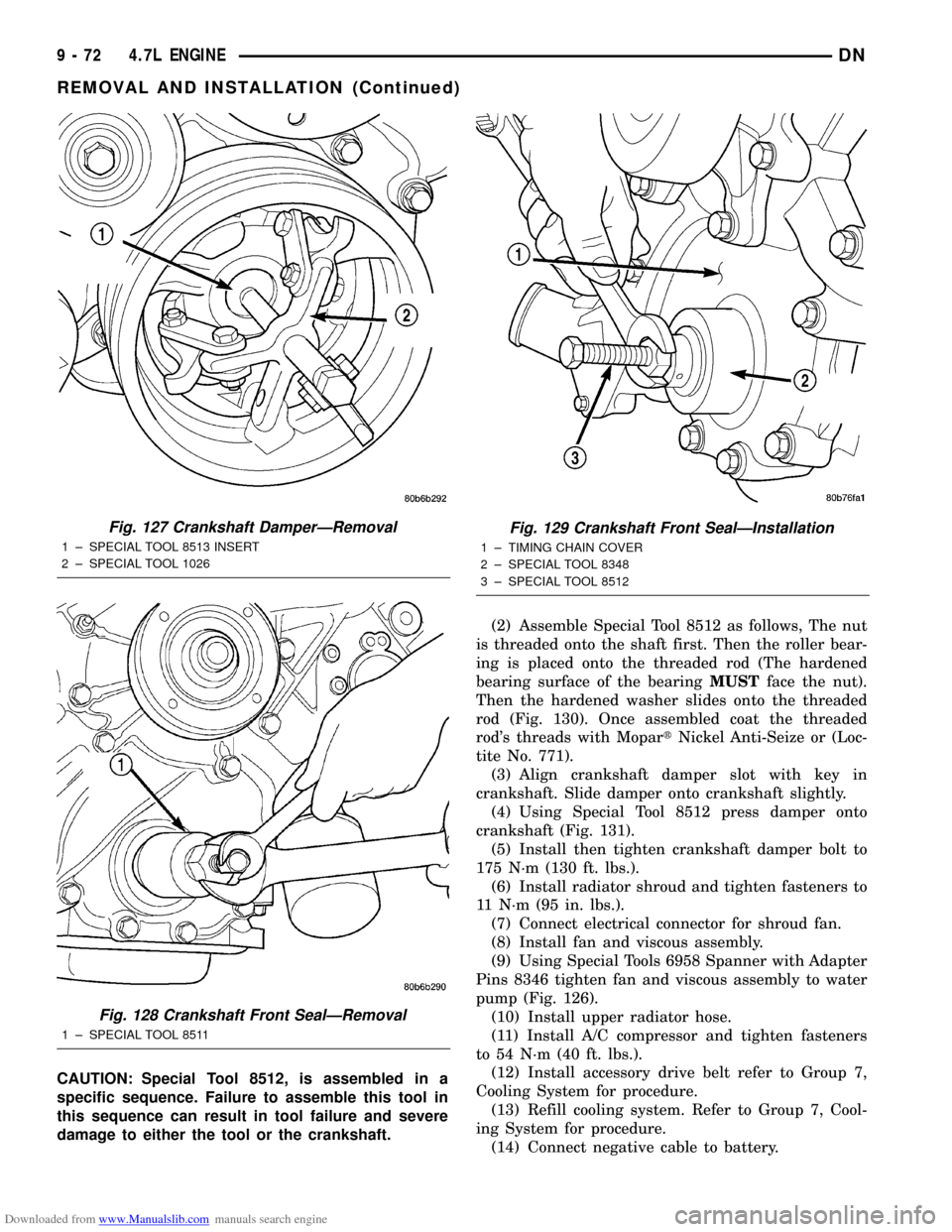
(12) Remove damper using Special Tools 8513
Insert and 1026 Three Jaw Puller (Fig. 127).
(13) Using Special Tool 8511, remove crankshaft
front seal (Fig. 128).
INSTALLATION
CAUTION: To prevent severe damage to the Crank-
shaft, Damper or Special Tool 8512, thoroughly
clean the damper bore and the crankshaft nose
before installing Damper.
(1) Using Special Tool 8348 and 8512, install
crankshaft front seal (Fig. 129).
Fig. 124 Oil Pump and Primary Timing Chain
Tightening Sequence
Fig. 125 Oil Pressure Sending Unit
1 ± BELT
2 ± OIL PRESSURE SENSOR
3 ± OIL FILTER
4 ± ELEC. CONNECTOR
Fig. 126 Fan AssemblyÐRemoval/Installation
1 ± SPECIAL TOOL 6958 SPANNER WRENCH WITH ADAPTER
PINS 8346
2±FAN
DN4.7L ENGINE 9 - 71
REMOVAL AND INSTALLATION (Continued)
Page 72 of 193
Downloaded from www.Manualslib.com manuals search engine CAUTION: Special Tool 8512, is assembled in a
specific sequence. Failure to assemble this tool in
this sequence can result in tool failure and severe
damage to either the tool or the crankshaft.(2) Assemble Special Tool 8512 as follows, The nut
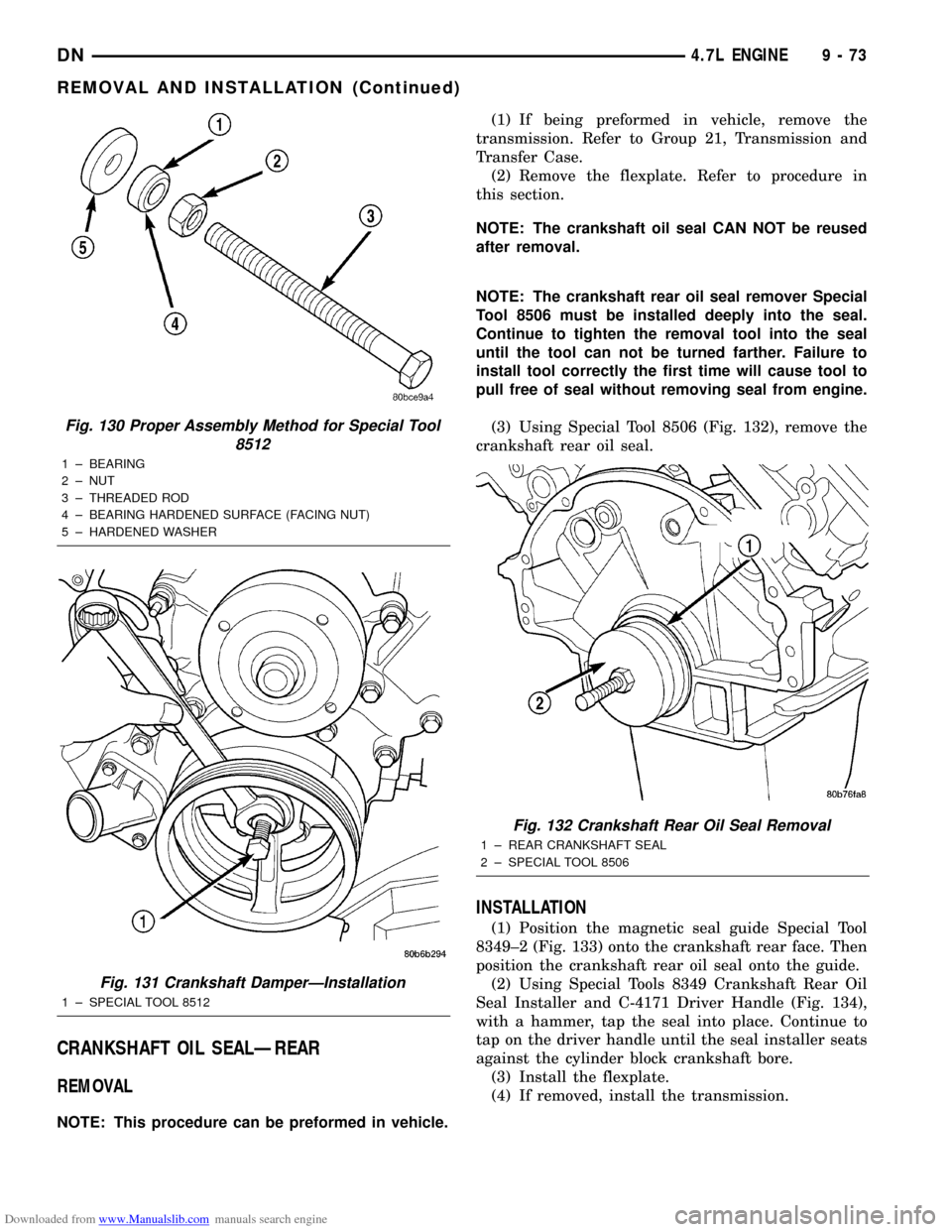
is threaded onto the shaft first. Then the roller bear-
ing is placed onto the threaded rod (The hardened
bearing surface of the bearingMUSTface the nut).
Then the hardened washer slides onto the threaded
rod (Fig. 130). Once assembled coat the threaded
rod's threads with MopartNickel Anti-Seize or (Loc-
tite No. 771).
(3) Align crankshaft damper slot with key in
crankshaft. Slide damper onto crankshaft slightly.
(4) Using Special Tool 8512 press damper onto
crankshaft (Fig. 131).
(5) Install then tighten crankshaft damper bolt to
175 N´m (130 ft. lbs.).
(6) Install radiator shroud and tighten fasteners to
11 N´m (95 in. lbs.).
(7) Connect electrical connector for shroud fan.
(8) Install fan and viscous assembly.
(9) Using Special Tools 6958 Spanner with Adapter
Pins 8346 tighten fan and viscous assembly to water
pump (Fig. 126).
(10) Install upper radiator hose.
(11) Install A/C compressor and tighten fasteners
to 54 N´m (40 ft. lbs.).
(12) Install accessory drive belt refer to Group 7,
Cooling System for procedure.
(13) Refill cooling system. Refer to Group 7, Cool-
ing System for procedure.
(14) Connect negative cable to battery.
Fig. 127 Crankshaft DamperÐRemoval
1 ± SPECIAL TOOL 8513 INSERT
2 ± SPECIAL TOOL 1026
Fig. 128 Crankshaft Front SealÐRemoval
1 ± SPECIAL TOOL 8511
Fig. 129 Crankshaft Front SealÐInstallation
1 ± TIMING CHAIN COVER
2 ± SPECIAL TOOL 8348
3 ± SPECIAL TOOL 8512
9 - 72 4.7L ENGINEDN
REMOVAL AND INSTALLATION (Continued)
Page 73 of 193
Downloaded from www.Manualslib.com manuals search engine CRANKSHAFT OIL SEALÐREAR
REMOVAL
NOTE: This procedure can be preformed in vehicle.(1) If being preformed in vehicle, remove the
transmission. Refer to Group 21, Transmission and
Transfer Case.
(2) Remove the flexplate. Refer to procedure in
this section.
NOTE: The crankshaft oil seal CAN NOT be reused
after removal.
NOTE: The crankshaft rear oil seal remover Special
Tool 8506 must be installed deeply into the seal.
Continue to tighten the removal tool into the seal
until the tool can not be turned farther. Failure to
install tool correctly the first time will cause tool to
pull free of seal without removing seal from engine.
(3) Using Special Tool 8506 (Fig. 132), remove the
crankshaft rear oil seal.
INSTALLATION
(1) Position the magnetic seal guide Special Tool
8349±2 (Fig. 133) onto the crankshaft rear face. Then
position the crankshaft rear oil seal onto the guide.
(2) Using Special Tools 8349 Crankshaft Rear Oil
Seal Installer and C-4171 Driver Handle (Fig. 134),
with a hammer, tap the seal into place. Continue to
tap on the driver handle until the seal installer seats
against the cylinder block crankshaft bore.
(3) Install the flexplate.
(4) If removed, install the transmission.
Fig. 130 Proper Assembly Method for Special Tool
8512
1 ± BEARING
2 ± NUT
3 ± THREADED ROD
4 ± BEARING HARDENED SURFACE (FACING NUT)
5 ± HARDENED WASHER
Fig. 131 Crankshaft DamperÐInstallation
1 ± SPECIAL TOOL 8512
Fig. 132 Crankshaft Rear Oil Seal Removal
1 ± REAR CRANKSHAFT SEAL
2 ± SPECIAL TOOL 8506
DN4.7L ENGINE 9 - 73
REMOVAL AND INSTALLATION (Continued)
Page 74 of 193
Downloaded from www.Manualslib.com manuals search engine ENGINE CORE PLUGS
REMOVAL
(1) Drain the cooling system. Refer to Group 7,
Cooling System for procedure.
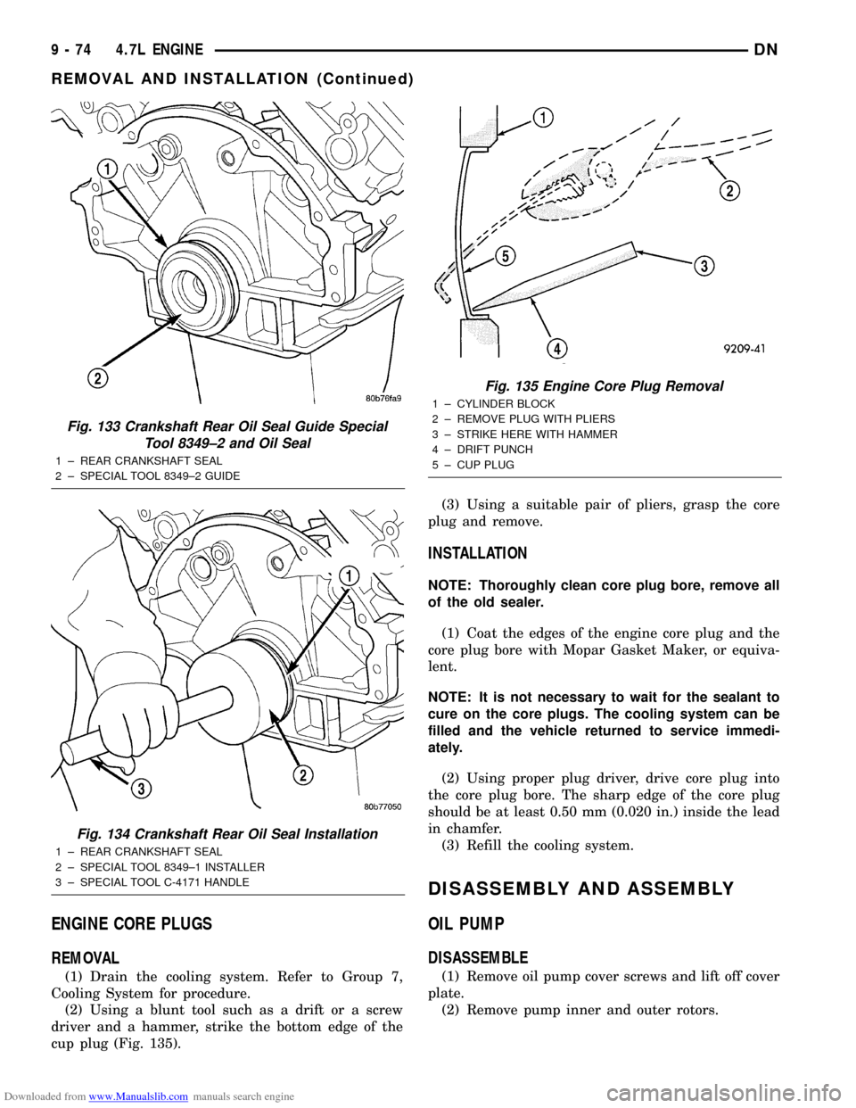
(2) Using a blunt tool such as a drift or a screw
driver and a hammer, strike the bottom edge of the
cup plug (Fig. 135).(3) Using a suitable pair of pliers, grasp the core
plug and remove.
INSTALLATION
NOTE: Thoroughly clean core plug bore, remove all
of the old sealer.
(1) Coat the edges of the engine core plug and the
core plug bore with Mopar Gasket Maker, or equiva-
lent.
NOTE: It is not necessary to wait for the sealant to
cure on the core plugs. The cooling system can be
filled and the vehicle returned to service immedi-
ately.
(2) Using proper plug driver, drive core plug into
the core plug bore. The sharp edge of the core plug
should be at least 0.50 mm (0.020 in.) inside the lead
in chamfer.
(3) Refill the cooling system.
DISASSEMBLY AND ASSEMBLY
OIL PUMP
DISASSEMBLE
(1) Remove oil pump cover screws and lift off cover
plate.
(2) Remove pump inner and outer rotors.
Fig. 133 Crankshaft Rear Oil Seal Guide Special
Tool 8349±2 and Oil Seal
1 ± REAR CRANKSHAFT SEAL
2 ± SPECIAL TOOL 8349±2 GUIDE
Fig. 134 Crankshaft Rear Oil Seal Installation
1 ± REAR CRANKSHAFT SEAL
2 ± SPECIAL TOOL 8349±1 INSTALLER
3 ± SPECIAL TOOL C-4171 HANDLE
Fig. 135 Engine Core Plug Removal
1 ± CYLINDER BLOCK
2 ± REMOVE PLUG WITH PLIERS
3 ± STRIKE HERE WITH HAMMER
4 ± DRIFT PUNCH
5 ± CUP PLUG
9 - 74 4.7L ENGINEDN
REMOVAL AND INSTALLATION (Continued)
Page 76 of 193
Downloaded from www.Manualslib.com manuals search engine PISTON AND CONNECTING ROD
CLEANING
CAUTION: DO NOT use a wire wheel or other abra-
sive cleaning devise to clean the pistons or con-
necting rods. The pistons have a Moly coating, this
coating must not be damaged.
(1) Using a suitable cleaning solvent clean the pis-
tons in warm water and towel dry.
(2) Use a wood or plastic scraper to clean the ring
land grooves.
CAUTION: DO NOT remove the piston pin from the
piston and connecting rod assembly.
INSPECTION
Check the crankshaft connecting rod journal for
excessive wear, taper and scoring.
Check the pistons for taper and elliptical shape
before they are fitted into the cylinder bore.
Replace any piston and connecting rod not meeting
the specifications.
OIL PAN
CLEANING
(1) Clean oil pan in solvent and wipe dry with a
clean cloth.
(2) Clean the oil pan gasket surface.DO NOTuse
a grinder wheel or other abrasive tool to clean seal-
ing surface.
(3) Clean oil screen and tube thoroughly in clean
solvent.
INSPECTION
(1) Inspect oil drain plug and plug hole for
stripped or damaged threads. Repair as necessary.
(2) Inspect the oil pan mounting flange for bends
or distortion. Straighten flange, if necessary.
OIL PUMP
CLEANING
(1) Wash all parts in a suitable solvent.
INSPECTION
CAUTION: Oil pump pressure relief valve and
spring should not be removed from the oil pump. If
the these components are disassembled andùr
removed from the pump the entire oil pump assem-
bly must be replaced.(1) Clean all parts thoroughly. Mating surface of
the oil pump housing should be smooth. If the pump
cover is scratched or grooved the oil pump assembly
should be replaced.
(2) Lay a straight edge across the pump cover sur-
face (Fig. 137). If a 0.025 mm (0.001 in.) feeler gauge
can be inserted between the cover and the straight
edge the oil pump assembly should be replaced.
(3) Measure the thickness of the outer rotor (Fig.
138). If the outer rotor thickness measures at 12.005
mm (0.400 in.) or less the oil pump assembly must be
replaced.
(4) Measure the diameter of the outer rotor. If the
outer rotor diameter measures at 85.925 mm (0.400
in.) or less the oil pump assembly must be replaced.
(5) Measure the thickness of the inner rotor (Fig.
139). If the inner rotor thickness measures at 12.005
mm (0.400 in.) or less then the oil pump assembly
must be replaced.
(6) Slide outer rotor into the body of the oil pump.
Press the outer rotor to one side of the oil pump body
and measure clearance between the outer rotor and
the body (Fig. 140). If the measurement is 0.47mm
(0.0186 in.) or more the oil pump assembly must be
replaced.
(7) Install the inner rotor in the into the oil pump
body. Measure the clearance between the inner and
outer rotors (Fig. 141). If the clearance between the
rotors is .150 mm (0.006 in.) or more the oil pump
assembly must be replaced.
(8) Place a straight edge across the body of the oil
pump (between the bolt holes), if a feeler gauge of
.095 mm (0.0038 in.) or greater can be inserted
between the straightedge and the rotors, the pump
must be replaced (Fig. 142).
NOTE: 4.7 Oil pump is released as an assembly.
There are no DaimlerChrysler part numbers for Sub-
Assembly components. In the event the oil pump is
not functioning or out of specification it must be
replaced as an assembly.
CYLINDER BLOCK
CLEANING
Thoroughly clean the oil pan and engine block gas-
ket surfaces.
Use compressed air to clean out:
²The galley at the oil filter adaptor hole.
²The front and rear oil galley holes.
²The feed holes for the crankshaft main bearings.
Once the block has been completely cleaned, apply
Loctite PST pipe sealant with Teflon 592 to the
threads of the front and rear oil galley plugs. Tighten
the plugs to 34 N´m (25 ft. lbs.) torque.
9 - 76 4.7L ENGINEDN
CLEANING AND INSPECTION (Continued)
Page 78 of 193
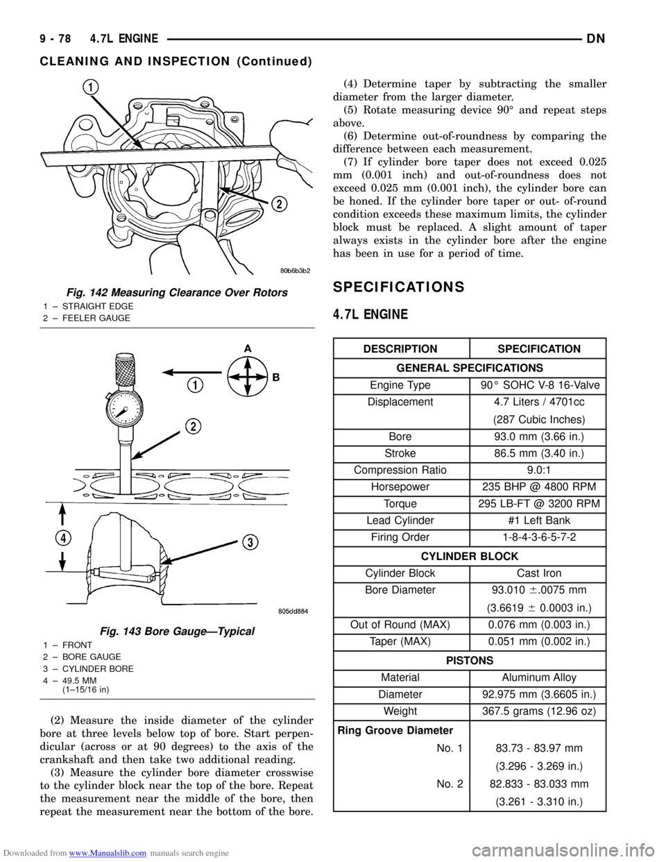
Downloaded from www.Manualslib.com manuals search engine (2) Measure the inside diameter of the cylinder
bore at three levels below top of bore. Start perpen-
dicular (across or at 90 degrees) to the axis of the
crankshaft and then take two additional reading.
(3) Measure the cylinder bore diameter crosswise
to the cylinder block near the top of the bore. Repeat
the measurement near the middle of the bore, then
repeat the measurement near the bottom of the bore.(4) Determine taper by subtracting the smaller
diameter from the larger diameter.
(5) Rotate measuring device 90É and repeat steps
above.
(6) Determine out-of-roundness by comparing the
difference between each measurement.
(7) If cylinder bore taper does not exceed 0.025
mm (0.001 inch) and out-of-roundness does not
exceed 0.025 mm (0.001 inch), the cylinder bore can
be honed. If the cylinder bore taper or out- of-round
condition exceeds these maximum limits, the cylinder
block must be replaced. A slight amount of taper
always exists in the cylinder bore after the engine
has been in use for a period of time.
SPECIFICATIONS
4.7L ENGINE
DESCRIPTION SPECIFICATION
GENERAL SPECIFICATIONS
Engine Type 90É SOHC V-8 16-Valve
Displacement 4.7 Liters / 4701cc
(287 Cubic Inches)
Bore 93.0 mm (3.66 in.)
Stroke 86.5 mm (3.40 in.)
Compression Ratio 9.0:1
Horsepower 235 BHP @ 4800 RPM
Torque 295 LB-FT @ 3200 RPM
Lead Cylinder #1 Left Bank
Firing Order 1-8-4-3-6-5-7-2
CYLINDER BLOCK
Cylinder Block Cast Iron
Bore Diameter 93.0106.0075 mm
(3.661960.0003 in.)
Out of Round (MAX) 0.076 mm (0.003 in.)
Taper (MAX) 0.051 mm (0.002 in.)
PISTONS
Material Aluminum Alloy
Diameter 92.975 mm (3.6605 in.)
Weight 367.5 grams (12.96 oz)
Ring Groove Diameter
No. 1 83.73 - 83.97 mm
(3.296 - 3.269 in.)
No. 2 82.833 - 83.033 mm
(3.261 - 3.310 in.)
Fig. 142 Measuring Clearance Over Rotors
1 ± STRAIGHT EDGE
2 ± FEELER GAUGE
Fig. 143 Bore GaugeÐTypical
1 ± FRONT
2 ± BORE GAUGE
3 ± CYLINDER BORE
4 ± 49.5 MM
(1±15/16 in)
9 - 78 4.7L ENGINEDN
CLEANING AND INSPECTION (Continued)