DODGE DURANGO 2000 1.G Manual PDF
Manufacturer: DODGE, Model Year: 2000, Model line: DURANGO, Model: DODGE DURANGO 2000 1.GPages: 193, PDF Size: 5.65 MB
Page 71 of 193
Downloaded from www.Manualslib.com manuals search engine (2) Remove accessory drive belt refer to Group 7,
Cooling System for procedure.
(3) Remove A/C compressor mouning fasteners and
set aside.(4) Drain cooling system. Refer to Group 7, Cooling
System for procedure.
(5) Remove upper radiator hose.
(6) Using Special Tools 6958 Spanner with Adapter
Pins 8346 loosen fan and viscous assembly from
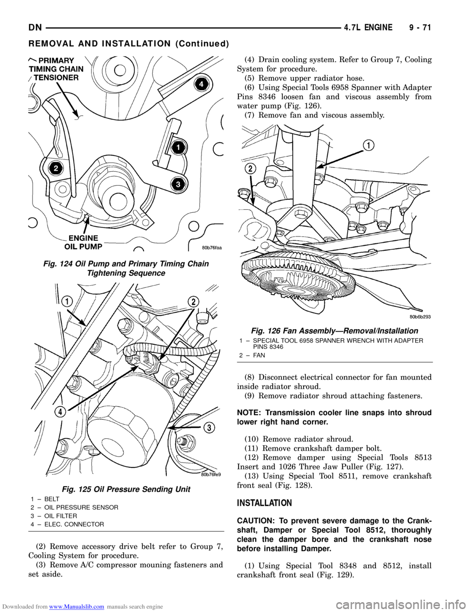
water pump (Fig. 126).
(7) Remove fan and viscous assembly.
(8) Disconnect electrical connector for fan mounted
inside radiator shroud.
(9) Remove radiator shroud attaching fasteners.
NOTE: Transmission cooler line snaps into shroud
lower right hand corner.
(10) Remove radiator shroud.
(11) Remove crankshaft damper bolt.
(12) Remove damper using Special Tools 8513
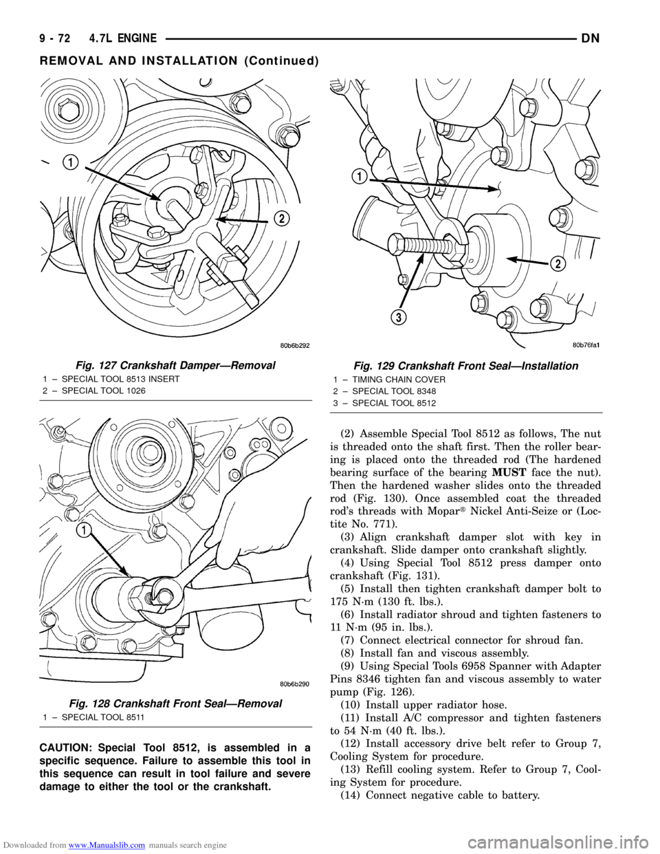
Insert and 1026 Three Jaw Puller (Fig. 127).
(13) Using Special Tool 8511, remove crankshaft
front seal (Fig. 128).
INSTALLATION
CAUTION: To prevent severe damage to the Crank-
shaft, Damper or Special Tool 8512, thoroughly
clean the damper bore and the crankshaft nose
before installing Damper.
(1) Using Special Tool 8348 and 8512, install
crankshaft front seal (Fig. 129).
Fig. 124 Oil Pump and Primary Timing Chain
Tightening Sequence
Fig. 125 Oil Pressure Sending Unit
1 ± BELT
2 ± OIL PRESSURE SENSOR
3 ± OIL FILTER
4 ± ELEC. CONNECTOR
Fig. 126 Fan AssemblyÐRemoval/Installation
1 ± SPECIAL TOOL 6958 SPANNER WRENCH WITH ADAPTER
PINS 8346
2±FAN
DN4.7L ENGINE 9 - 71
REMOVAL AND INSTALLATION (Continued)
Page 72 of 193
Downloaded from www.Manualslib.com manuals search engine CAUTION: Special Tool 8512, is assembled in a
specific sequence. Failure to assemble this tool in
this sequence can result in tool failure and severe
damage to either the tool or the crankshaft.(2) Assemble Special Tool 8512 as follows, The nut
is threaded onto the shaft first. Then the roller bear-
ing is placed onto the threaded rod (The hardened
bearing surface of the bearingMUSTface the nut).
Then the hardened washer slides onto the threaded
rod (Fig. 130). Once assembled coat the threaded
rod's threads with MopartNickel Anti-Seize or (Loc-
tite No. 771).
(3) Align crankshaft damper slot with key in
crankshaft. Slide damper onto crankshaft slightly.
(4) Using Special Tool 8512 press damper onto
crankshaft (Fig. 131).
(5) Install then tighten crankshaft damper bolt to
175 N´m (130 ft. lbs.).
(6) Install radiator shroud and tighten fasteners to
11 N´m (95 in. lbs.).
(7) Connect electrical connector for shroud fan.
(8) Install fan and viscous assembly.
(9) Using Special Tools 6958 Spanner with Adapter
Pins 8346 tighten fan and viscous assembly to water
pump (Fig. 126).
(10) Install upper radiator hose.
(11) Install A/C compressor and tighten fasteners
to 54 N´m (40 ft. lbs.).
(12) Install accessory drive belt refer to Group 7,
Cooling System for procedure.
(13) Refill cooling system. Refer to Group 7, Cool-
ing System for procedure.
(14) Connect negative cable to battery.
Fig. 127 Crankshaft DamperÐRemoval
1 ± SPECIAL TOOL 8513 INSERT
2 ± SPECIAL TOOL 1026
Fig. 128 Crankshaft Front SealÐRemoval
1 ± SPECIAL TOOL 8511
Fig. 129 Crankshaft Front SealÐInstallation
1 ± TIMING CHAIN COVER
2 ± SPECIAL TOOL 8348
3 ± SPECIAL TOOL 8512
9 - 72 4.7L ENGINEDN
REMOVAL AND INSTALLATION (Continued)
Page 73 of 193
Downloaded from www.Manualslib.com manuals search engine CRANKSHAFT OIL SEALÐREAR
REMOVAL
NOTE: This procedure can be preformed in vehicle.(1) If being preformed in vehicle, remove the
transmission. Refer to Group 21, Transmission and
Transfer Case.
(2) Remove the flexplate. Refer to procedure in
this section.
NOTE: The crankshaft oil seal CAN NOT be reused
after removal.
NOTE: The crankshaft rear oil seal remover Special
Tool 8506 must be installed deeply into the seal.
Continue to tighten the removal tool into the seal
until the tool can not be turned farther. Failure to
install tool correctly the first time will cause tool to
pull free of seal without removing seal from engine.
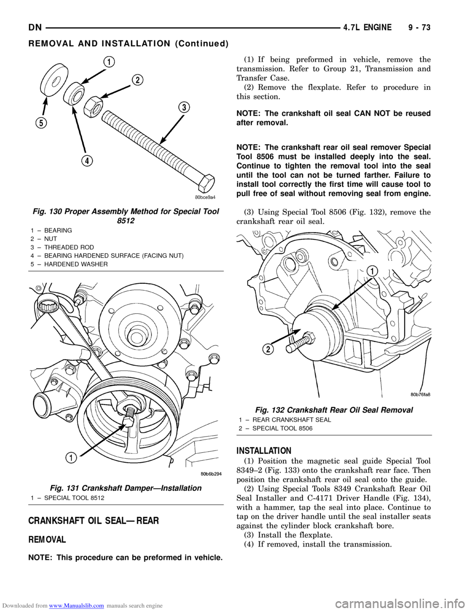
(3) Using Special Tool 8506 (Fig. 132), remove the
crankshaft rear oil seal.
INSTALLATION
(1) Position the magnetic seal guide Special Tool
8349±2 (Fig. 133) onto the crankshaft rear face. Then
position the crankshaft rear oil seal onto the guide.
(2) Using Special Tools 8349 Crankshaft Rear Oil
Seal Installer and C-4171 Driver Handle (Fig. 134),
with a hammer, tap the seal into place. Continue to
tap on the driver handle until the seal installer seats
against the cylinder block crankshaft bore.
(3) Install the flexplate.
(4) If removed, install the transmission.
Fig. 130 Proper Assembly Method for Special Tool
8512
1 ± BEARING
2 ± NUT
3 ± THREADED ROD
4 ± BEARING HARDENED SURFACE (FACING NUT)
5 ± HARDENED WASHER
Fig. 131 Crankshaft DamperÐInstallation
1 ± SPECIAL TOOL 8512
Fig. 132 Crankshaft Rear Oil Seal Removal
1 ± REAR CRANKSHAFT SEAL
2 ± SPECIAL TOOL 8506
DN4.7L ENGINE 9 - 73
REMOVAL AND INSTALLATION (Continued)
Page 74 of 193
Downloaded from www.Manualslib.com manuals search engine ENGINE CORE PLUGS
REMOVAL
(1) Drain the cooling system. Refer to Group 7,
Cooling System for procedure.
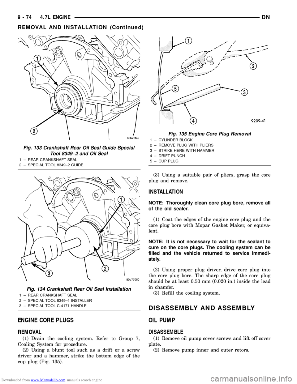
(2) Using a blunt tool such as a drift or a screw
driver and a hammer, strike the bottom edge of the
cup plug (Fig. 135).(3) Using a suitable pair of pliers, grasp the core
plug and remove.
INSTALLATION
NOTE: Thoroughly clean core plug bore, remove all
of the old sealer.
(1) Coat the edges of the engine core plug and the
core plug bore with Mopar Gasket Maker, or equiva-
lent.
NOTE: It is not necessary to wait for the sealant to
cure on the core plugs. The cooling system can be
filled and the vehicle returned to service immedi-
ately.
(2) Using proper plug driver, drive core plug into
the core plug bore. The sharp edge of the core plug
should be at least 0.50 mm (0.020 in.) inside the lead
in chamfer.
(3) Refill the cooling system.
DISASSEMBLY AND ASSEMBLY
OIL PUMP
DISASSEMBLE
(1) Remove oil pump cover screws and lift off cover
plate.
(2) Remove pump inner and outer rotors.
Fig. 133 Crankshaft Rear Oil Seal Guide Special
Tool 8349±2 and Oil Seal
1 ± REAR CRANKSHAFT SEAL
2 ± SPECIAL TOOL 8349±2 GUIDE
Fig. 134 Crankshaft Rear Oil Seal Installation
1 ± REAR CRANKSHAFT SEAL
2 ± SPECIAL TOOL 8349±1 INSTALLER
3 ± SPECIAL TOOL C-4171 HANDLE
Fig. 135 Engine Core Plug Removal
1 ± CYLINDER BLOCK
2 ± REMOVE PLUG WITH PLIERS
3 ± STRIKE HERE WITH HAMMER
4 ± DRIFT PUNCH
5 ± CUP PLUG
9 - 74 4.7L ENGINEDN
REMOVAL AND INSTALLATION (Continued)
Page 75 of 193
Downloaded from www.Manualslib.com manuals search engine NOTE: Once the oil pressure relief valve, cup plug,
and pin are removed, the pump assembly must be
replaced.
(3) If it is necessary to remove the pressure relief
valve, drive the roll pin from pump housing and
remove cup plug, spring and valve.
ASSEMBLE
(1) Wash all parts in a suitable solvent and inspect
carefully for damage or wear.
(2) Install inner and outer rotors
(3) Install oil pump cover plate and install cover
bolts and tighten them to 12 N´m (105 in. lbs.).
(4) Prime oil pump before installation by filling
rotor cavity with engine oil.
(5) If oil pressure is low and pump is within spec-
ifications, inspect for worn engine bearings or other
causes for oil pressure loss.
CLEANING AND INSPECTION
INTAKE MANIFOLD
CLEANING
NOTE: There is NO approved repair procedure for
the intake manifold. If severe damage is found dur-
ing inspection, the intake manifold must be
replaced.
Before installing the intake manifold thoroughly
clean the mating surfaces. Use a suitable cleaning
solvent, then air dry.
INSPECTION
(1) Inspect the intake sealing surface for cracks,
nicks and distortion.
(2) Inspect the intake manifold vacuum hose fit-
tings for looseness or blockage.
(3) Inspect the manifold to throttle body mating
surface for cracks, nicks and distortion.
EXHAUST MANIFOLD
CLEANING
(1) Clean the exhaust manifold using a suitable
cleaning solvent, then allow to air dry.
(2) Clean all gasket residue from the manifold
mating surface.
INSPECTION
(1) Inspect the exhaust manifold for cracks in the
mating surface and at every mounting bolt hole.
(2) Using a straight edge and a feeler gauge, check
the mating surface for warp and twist.(3) Inspect the manifold to exhaust pipe mating
surface for cracks, gouges, or other damage that
would prevent sealing.
CYLINDER HEADS
CLEANING
CYLINDER HEAD GASKET SURFACE PREPARATION
To ensure engine gasket sealing, proper surface
preparation must be performed, especially with the
use of aluminum engine components.
Never use the following to clean gasket surfaces:
²never use a metal scraper.
²never use an abrasive pad or paper to
clean the cylinder block.
²never use a high speed power tool or wire
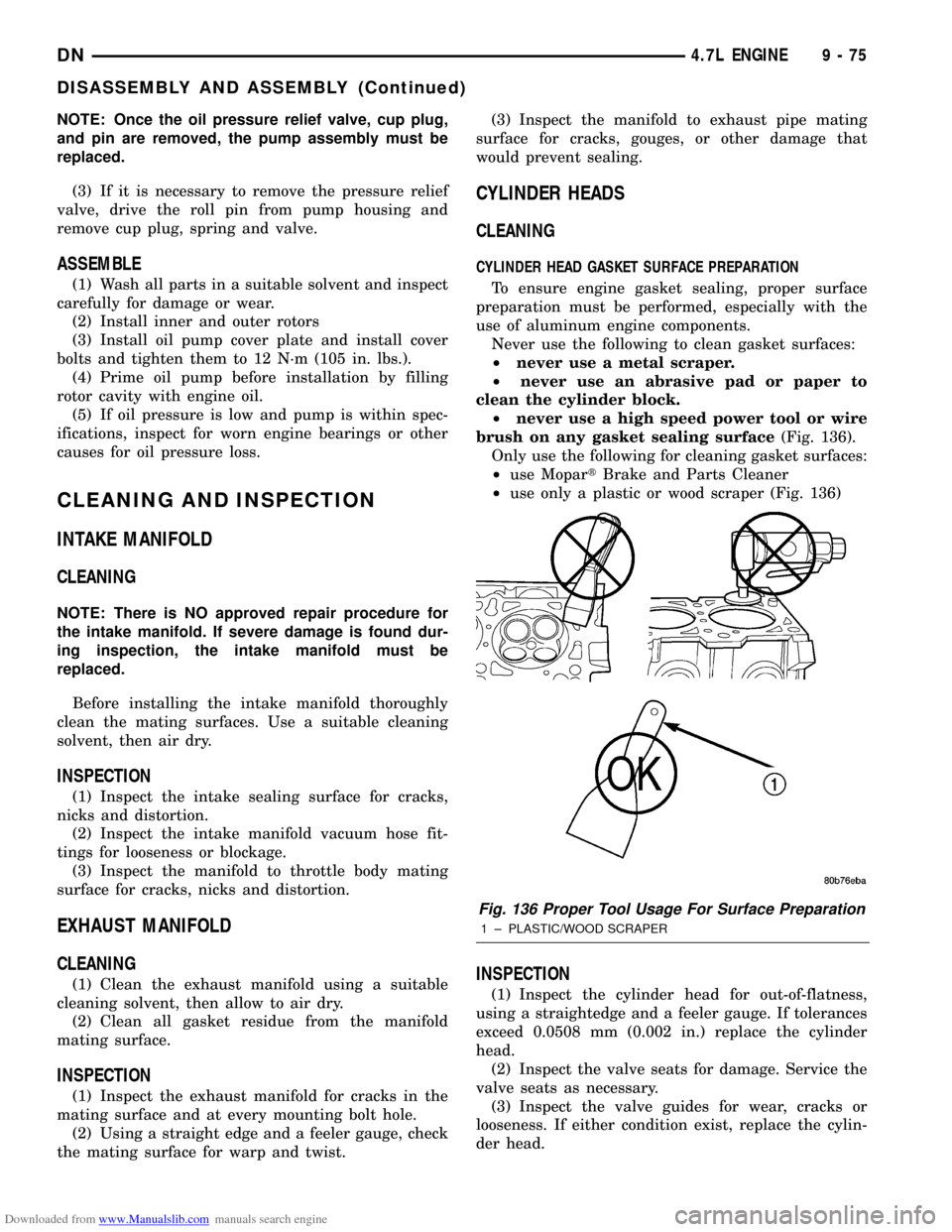
brush on any gasket sealing surface(Fig. 136).
Only use the following for cleaning gasket surfaces:
²use MopartBrake and Parts Cleaner
²use only a plastic or wood scraper (Fig. 136)
INSPECTION
(1) Inspect the cylinder head for out-of-flatness,
using a straightedge and a feeler gauge. If tolerances
exceed 0.0508 mm (0.002 in.) replace the cylinder
head.
(2) Inspect the valve seats for damage. Service the
valve seats as necessary.
(3) Inspect the valve guides for wear, cracks or
looseness. If either condition exist, replace the cylin-
der head.
Fig. 136 Proper Tool Usage For Surface Preparation
1 ± PLASTIC/WOOD SCRAPER
DN4.7L ENGINE 9 - 75
DISASSEMBLY AND ASSEMBLY (Continued)
Page 76 of 193
Downloaded from www.Manualslib.com manuals search engine PISTON AND CONNECTING ROD
CLEANING
CAUTION: DO NOT use a wire wheel or other abra-
sive cleaning devise to clean the pistons or con-
necting rods. The pistons have a Moly coating, this
coating must not be damaged.
(1) Using a suitable cleaning solvent clean the pis-
tons in warm water and towel dry.
(2) Use a wood or plastic scraper to clean the ring
land grooves.
CAUTION: DO NOT remove the piston pin from the
piston and connecting rod assembly.
INSPECTION
Check the crankshaft connecting rod journal for
excessive wear, taper and scoring.
Check the pistons for taper and elliptical shape
before they are fitted into the cylinder bore.
Replace any piston and connecting rod not meeting
the specifications.
OIL PAN
CLEANING
(1) Clean oil pan in solvent and wipe dry with a
clean cloth.
(2) Clean the oil pan gasket surface.DO NOTuse
a grinder wheel or other abrasive tool to clean seal-
ing surface.
(3) Clean oil screen and tube thoroughly in clean
solvent.
INSPECTION
(1) Inspect oil drain plug and plug hole for
stripped or damaged threads. Repair as necessary.
(2) Inspect the oil pan mounting flange for bends
or distortion. Straighten flange, if necessary.
OIL PUMP
CLEANING
(1) Wash all parts in a suitable solvent.
INSPECTION
CAUTION: Oil pump pressure relief valve and
spring should not be removed from the oil pump. If
the these components are disassembled andùr
removed from the pump the entire oil pump assem-
bly must be replaced.(1) Clean all parts thoroughly. Mating surface of
the oil pump housing should be smooth. If the pump
cover is scratched or grooved the oil pump assembly
should be replaced.
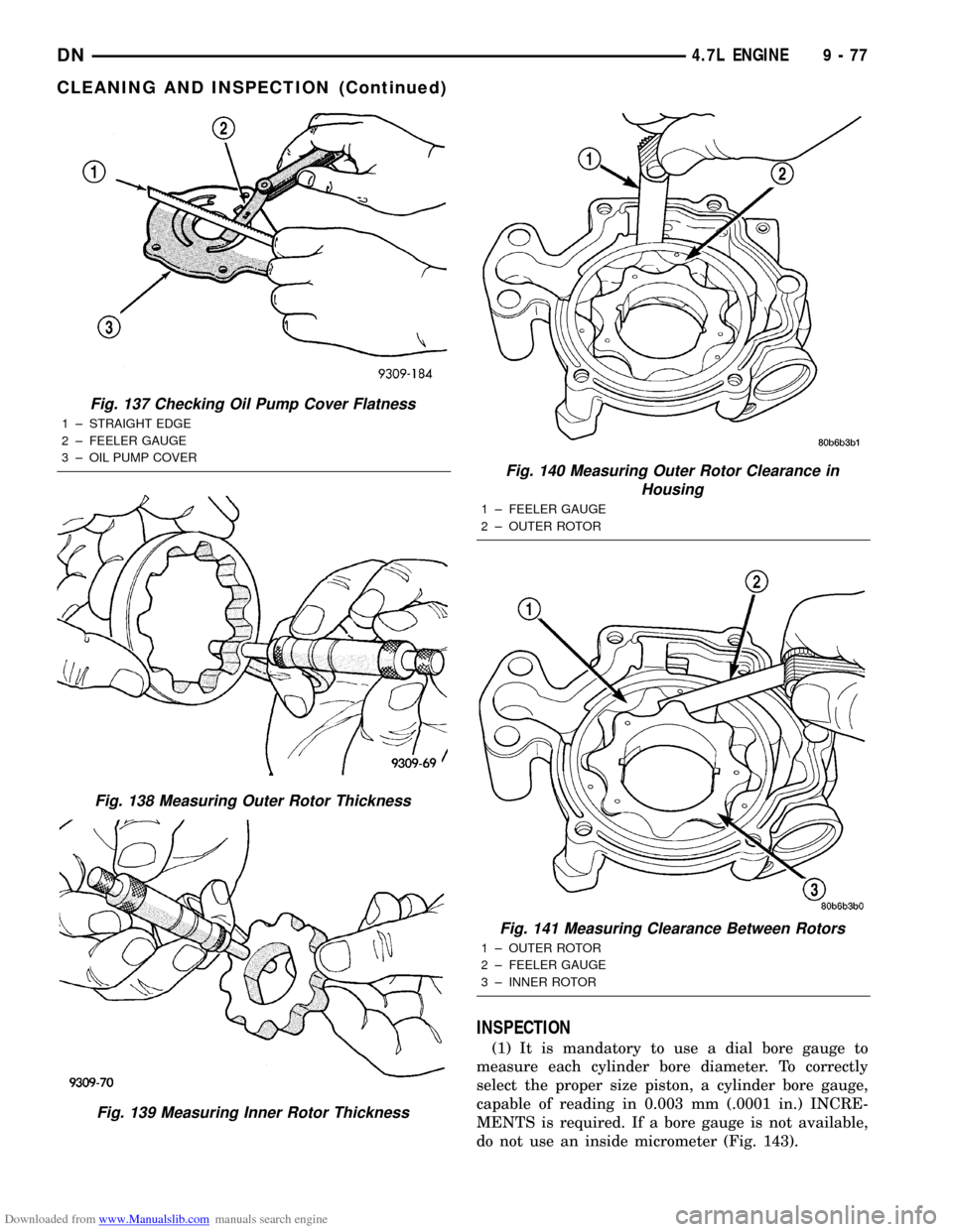
(2) Lay a straight edge across the pump cover sur-
face (Fig. 137). If a 0.025 mm (0.001 in.) feeler gauge
can be inserted between the cover and the straight
edge the oil pump assembly should be replaced.
(3) Measure the thickness of the outer rotor (Fig.
138). If the outer rotor thickness measures at 12.005
mm (0.400 in.) or less the oil pump assembly must be
replaced.
(4) Measure the diameter of the outer rotor. If the
outer rotor diameter measures at 85.925 mm (0.400
in.) or less the oil pump assembly must be replaced.
(5) Measure the thickness of the inner rotor (Fig.
139). If the inner rotor thickness measures at 12.005
mm (0.400 in.) or less then the oil pump assembly
must be replaced.
(6) Slide outer rotor into the body of the oil pump.
Press the outer rotor to one side of the oil pump body
and measure clearance between the outer rotor and
the body (Fig. 140). If the measurement is 0.47mm
(0.0186 in.) or more the oil pump assembly must be
replaced.
(7) Install the inner rotor in the into the oil pump
body. Measure the clearance between the inner and
outer rotors (Fig. 141). If the clearance between the
rotors is .150 mm (0.006 in.) or more the oil pump
assembly must be replaced.
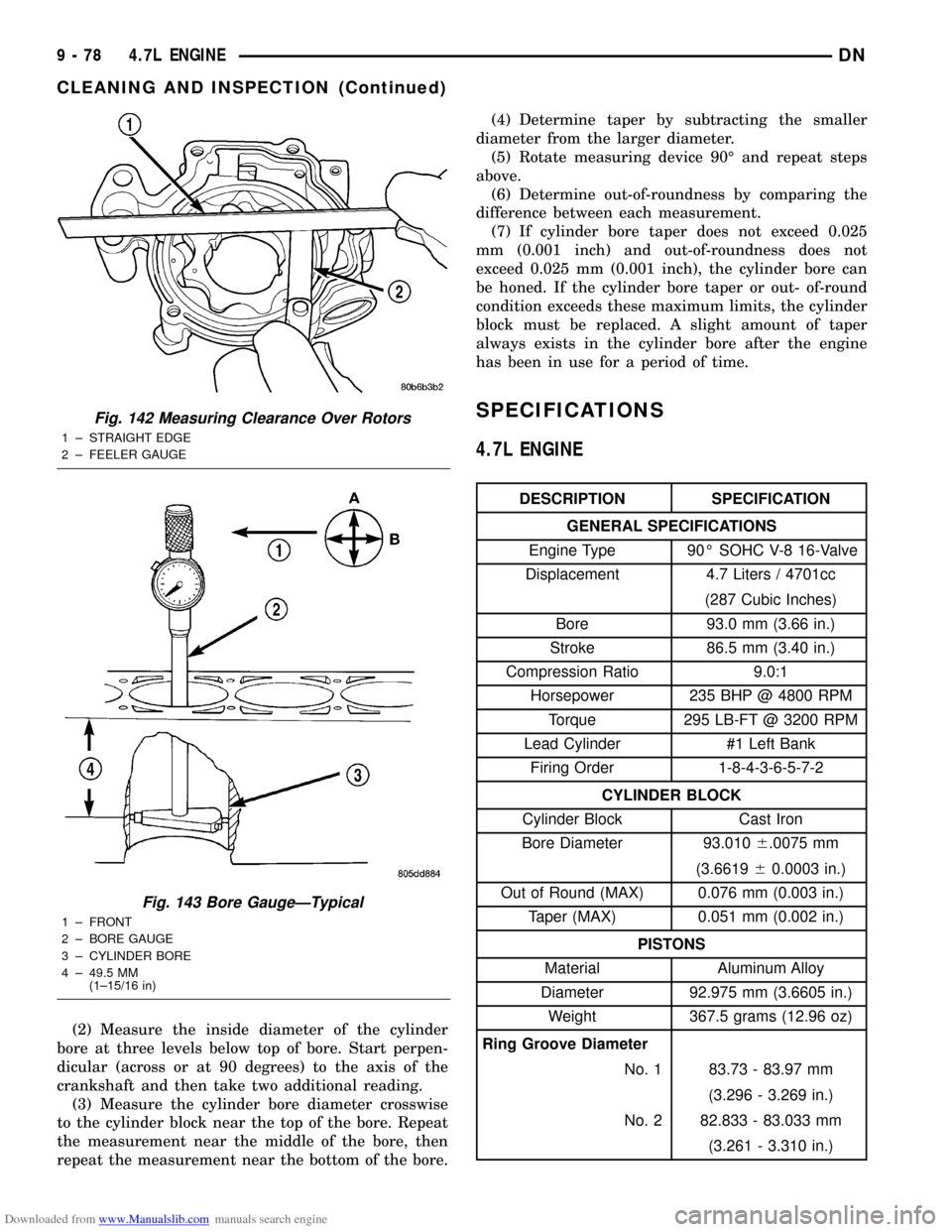
(8) Place a straight edge across the body of the oil
pump (between the bolt holes), if a feeler gauge of
.095 mm (0.0038 in.) or greater can be inserted
between the straightedge and the rotors, the pump
must be replaced (Fig. 142).
NOTE: 4.7 Oil pump is released as an assembly.
There are no DaimlerChrysler part numbers for Sub-
Assembly components. In the event the oil pump is
not functioning or out of specification it must be
replaced as an assembly.
CYLINDER BLOCK
CLEANING
Thoroughly clean the oil pan and engine block gas-
ket surfaces.
Use compressed air to clean out:
²The galley at the oil filter adaptor hole.
²The front and rear oil galley holes.
²The feed holes for the crankshaft main bearings.
Once the block has been completely cleaned, apply
Loctite PST pipe sealant with Teflon 592 to the
threads of the front and rear oil galley plugs. Tighten
the plugs to 34 N´m (25 ft. lbs.) torque.
9 - 76 4.7L ENGINEDN
CLEANING AND INSPECTION (Continued)
Page 77 of 193
Downloaded from www.Manualslib.com manuals search engine INSPECTION
(1) It is mandatory to use a dial bore gauge to
measure each cylinder bore diameter. To correctly
select the proper size piston, a cylinder bore gauge,
capable of reading in 0.003 mm (.0001 in.) INCRE-
MENTS is required. If a bore gauge is not available,
do not use an inside micrometer (Fig. 143).
Fig. 137 Checking Oil Pump Cover Flatness
1 ± STRAIGHT EDGE
2 ± FEELER GAUGE
3 ± OIL PUMP COVER
Fig. 138 Measuring Outer Rotor Thickness
Fig. 139 Measuring Inner Rotor Thickness
Fig. 140 Measuring Outer Rotor Clearance in
Housing
1 ± FEELER GAUGE
2 ± OUTER ROTOR
Fig. 141 Measuring Clearance Between Rotors
1 ± OUTER ROTOR
2 ± FEELER GAUGE
3 ± INNER ROTOR
DN4.7L ENGINE 9 - 77
CLEANING AND INSPECTION (Continued)
Page 78 of 193
Downloaded from www.Manualslib.com manuals search engine (2) Measure the inside diameter of the cylinder
bore at three levels below top of bore. Start perpen-
dicular (across or at 90 degrees) to the axis of the
crankshaft and then take two additional reading.
(3) Measure the cylinder bore diameter crosswise
to the cylinder block near the top of the bore. Repeat
the measurement near the middle of the bore, then
repeat the measurement near the bottom of the bore.(4) Determine taper by subtracting the smaller
diameter from the larger diameter.
(5) Rotate measuring device 90É and repeat steps
above.
(6) Determine out-of-roundness by comparing the
difference between each measurement.
(7) If cylinder bore taper does not exceed 0.025
mm (0.001 inch) and out-of-roundness does not
exceed 0.025 mm (0.001 inch), the cylinder bore can
be honed. If the cylinder bore taper or out- of-round
condition exceeds these maximum limits, the cylinder
block must be replaced. A slight amount of taper
always exists in the cylinder bore after the engine
has been in use for a period of time.
SPECIFICATIONS
4.7L ENGINE
DESCRIPTION SPECIFICATION
GENERAL SPECIFICATIONS
Engine Type 90É SOHC V-8 16-Valve
Displacement 4.7 Liters / 4701cc
(287 Cubic Inches)
Bore 93.0 mm (3.66 in.)
Stroke 86.5 mm (3.40 in.)
Compression Ratio 9.0:1
Horsepower 235 BHP @ 4800 RPM
Torque 295 LB-FT @ 3200 RPM
Lead Cylinder #1 Left Bank
Firing Order 1-8-4-3-6-5-7-2
CYLINDER BLOCK
Cylinder Block Cast Iron
Bore Diameter 93.0106.0075 mm
(3.661960.0003 in.)
Out of Round (MAX) 0.076 mm (0.003 in.)
Taper (MAX) 0.051 mm (0.002 in.)
PISTONS
Material Aluminum Alloy
Diameter 92.975 mm (3.6605 in.)
Weight 367.5 grams (12.96 oz)
Ring Groove Diameter
No. 1 83.73 - 83.97 mm
(3.296 - 3.269 in.)
No. 2 82.833 - 83.033 mm
(3.261 - 3.310 in.)
Fig. 142 Measuring Clearance Over Rotors
1 ± STRAIGHT EDGE
2 ± FEELER GAUGE
Fig. 143 Bore GaugeÐTypical
1 ± FRONT
2 ± BORE GAUGE
3 ± CYLINDER BORE
4 ± 49.5 MM
(1±15/16 in)
9 - 78 4.7L ENGINEDN
CLEANING AND INSPECTION (Continued)
Page 79 of 193
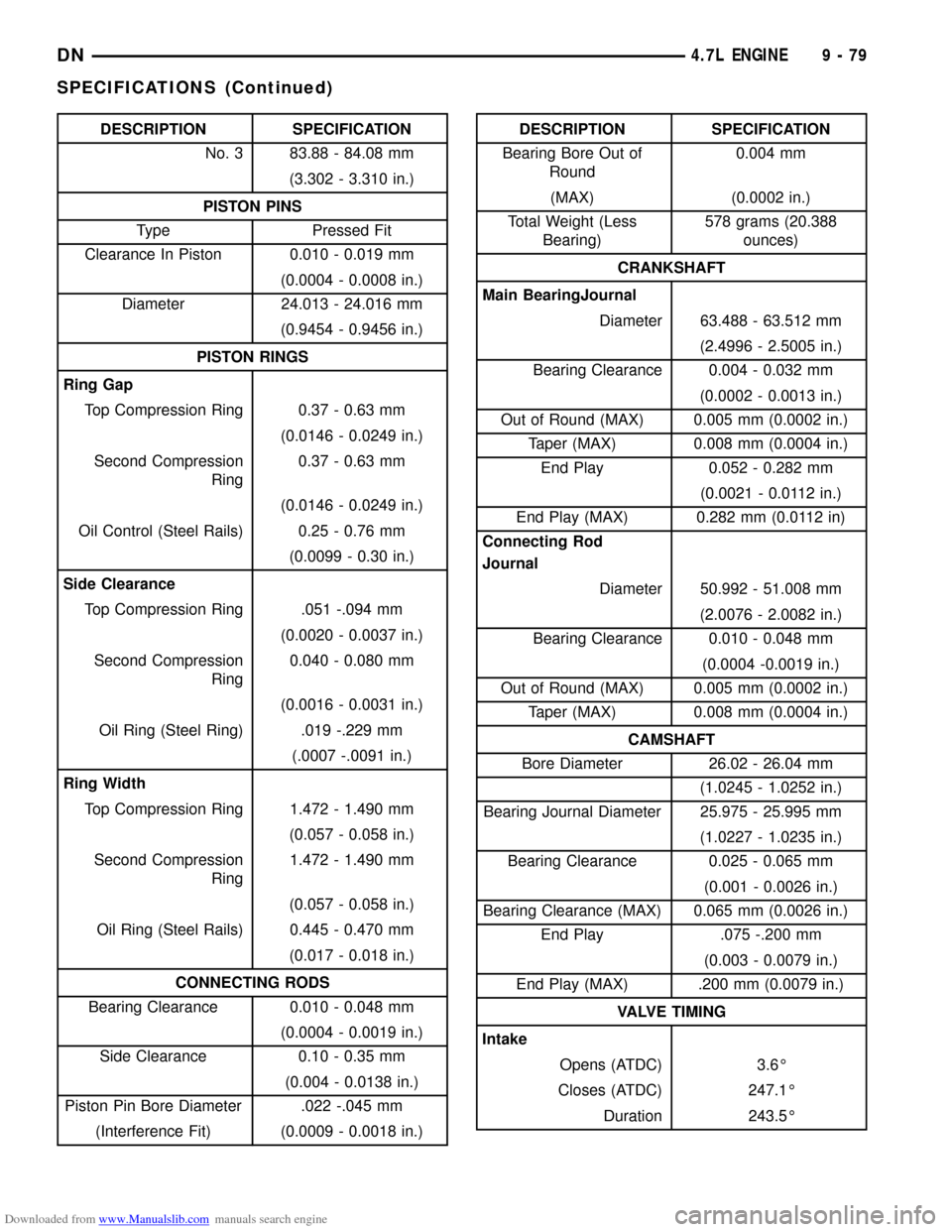
Downloaded from www.Manualslib.com manuals search engine DESCRIPTION SPECIFICATION
No. 3 83.88 - 84.08 mm
(3.302 - 3.310 in.)
PISTON PINS
Type Pressed Fit
Clearance In Piston 0.010 - 0.019 mm
(0.0004 - 0.0008 in.)
Diameter 24.013 - 24.016 mm
(0.9454 - 0.9456 in.)
PISTON RINGS
Ring Gap
Top Compression Ring 0.37 - 0.63 mm
(0.0146 - 0.0249 in.)
Second Compression
Ring0.37 - 0.63 mm
(0.0146 - 0.0249 in.)
Oil Control (Steel Rails) 0.25 - 0.76 mm
(0.0099 - 0.30 in.)
Side Clearance
Top Compression Ring .051 -.094 mm
(0.0020 - 0.0037 in.)
Second Compression
Ring0.040 - 0.080 mm
(0.0016 - 0.0031 in.)
Oil Ring (Steel Ring) .019 -.229 mm
(.0007 -.0091 in.)
Ring Width
Top Compression Ring 1.472 - 1.490 mm
(0.057 - 0.058 in.)
Second Compression
Ring1.472 - 1.490 mm
(0.057 - 0.058 in.)
Oil Ring (Steel Rails) 0.445 - 0.470 mm
(0.017 - 0.018 in.)
CONNECTING RODS
Bearing Clearance 0.010 - 0.048 mm
(0.0004 - 0.0019 in.)
Side Clearance 0.10 - 0.35 mm
(0.004 - 0.0138 in.)
Piston Pin Bore Diameter .022 -.045 mm
(Interference Fit) (0.0009 - 0.0018 in.)DESCRIPTION SPECIFICATION
Bearing Bore Out of
Round0.004 mm
(MAX) (0.0002 in.)
Total Weight (Less
Bearing)578 grams (20.388
ounces)
CRANKSHAFT
Main BearingJournal
Diameter 63.488 - 63.512 mm
(2.4996 - 2.5005 in.)
Bearing Clearance 0.004 - 0.032 mm
(0.0002 - 0.0013 in.)
Out of Round (MAX) 0.005 mm (0.0002 in.)
Taper (MAX) 0.008 mm (0.0004 in.)
End Play 0.052 - 0.282 mm
(0.0021 - 0.0112 in.)
End Play (MAX) 0.282 mm (0.0112 in)
Connecting Rod
Journal
Diameter 50.992 - 51.008 mm
(2.0076 - 2.0082 in.)
Bearing Clearance 0.010 - 0.048 mm
(0.0004 -0.0019 in.)
Out of Round (MAX) 0.005 mm (0.0002 in.)
Taper (MAX) 0.008 mm (0.0004 in.)
CAMSHAFT
Bore Diameter 26.02 - 26.04 mm
(1.0245 - 1.0252 in.)
Bearing Journal Diameter 25.975 - 25.995 mm
(1.0227 - 1.0235 in.)
Bearing Clearance 0.025 - 0.065 mm
(0.001 - 0.0026 in.)
Bearing Clearance (MAX) 0.065 mm (0.0026 in.)
End Play .075 -.200 mm
(0.003 - 0.0079 in.)
End Play (MAX) .200 mm (0.0079 in.)
VALVE TIMING
Intake
Opens (ATDC) 3.6É
Closes (ATDC) 247.1É
Duration 243.5É
DN4.7L ENGINE 9 - 79
SPECIFICATIONS (Continued)
Page 80 of 193
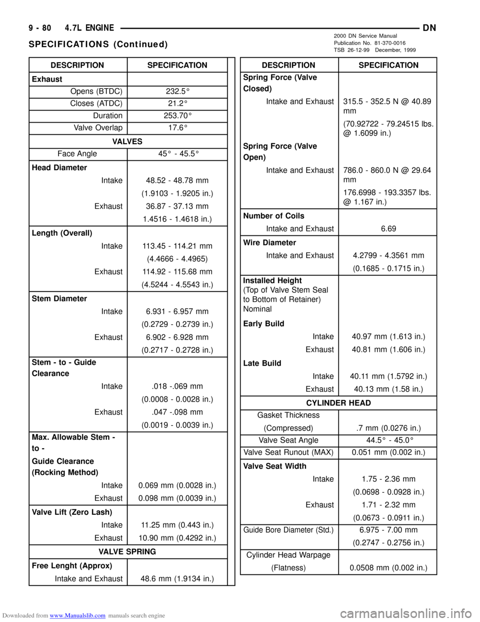
Downloaded from www.Manualslib.com manuals search engine DESCRIPTION SPECIFICATION
Exhaust
Opens (BTDC) 232.5É
Closes (ATDC) 21.2É
Duration 253.70É
Valve Overlap 17.6É
VA LV E S
Face Angle 45É - 45.5É
Head Diameter
Intake 48.52 - 48.78 mm
(1.9103 - 1.9205 in.)
Exhaust 36.87 - 37.13 mm
1.4516 - 1.4618 in.)
Length (Overall)
Intake 113.45 - 114.21 mm
(4.4666 - 4.4965)
Exhaust 114.92 - 115.68 mm
(4.5244 - 4.5543 in.)
Stem Diameter
Intake 6.931 - 6.957 mm
(0.2729 - 0.2739 in.)
Exhaust 6.902 - 6.928 mm
(0.2717 - 0.2728 in.)
Stem - to - Guide
Clearance
Intake .018 -.069 mm
(0.0008 - 0.0028 in.)
Exhaust .047 -.098 mm
(0.0019 - 0.0039 in.)
Max. Allowable Stem -
to -
Guide Clearance
(Rocking Method)
Intake 0.069 mm (0.0028 in.)
Exhaust 0.098 mm (0.0039 in.)
Valve Lift (Zero Lash)
Intake 11.25 mm (0.443 in.)
Exhaust 10.90 mm (0.4292 in.)
VALVE SPRING
Free Lenght (Approx)
Intake and Exhaust 48.6 mm (1.9134 in.)DESCRIPTION SPECIFICATION
Spring Force (Valve
Closed)
Intake and Exhaust 315.5 - 352.5 N @ 40.89
mm
(70.92722 - 79.24515 lbs.
@ 1.6099 in.)
Spring Force (Valve
Open)
Intake and Exhaust 786.0 - 860.0 N @ 29.64
mm
176.6998 - 193.3357 lbs.
@ 1.167 in.)
Number of Coils
Intake and Exhaust 6.69
Wire Diameter
Intake and Exhaust 4.2799 - 4.3561 mm
(0.1685 - 0.1715 in.)
Installed Height
(Top of Valve Stem Seal
to Bottom of Retainer)
Nominal
Early Build
Intake 40.97 mm (1.613 in.)
Exhaust 40.81 mm (1.606 in.)
Late Build
Intake 40.11 mm (1.5792 in.)
Exhaust 40.13 mm (1.58 in.)
CYLINDER HEAD
Gasket Thickness
(Compressed) .7 mm (0.0276 in.)
Valve Seat Angle 44.5É - 45.0É
Valve Seat Runout (MAX) 0.051 mm (0.002 in.)
Valve Seat Width
Intake 1.75 - 2.36 mm
(0.0698 - 0.0928 in.)
Exhaust 1.71 - 2.32 mm
(0.0673 - 0.0911 in.)
Guide Bore Diameter (Std.)6.975 - 7.00 mm
(0.2747 - 0.2756 in.)
Cylinder Head Warpage
(Flatness) 0.0508 mm (0.002 in.)
9 - 80 4.7L ENGINEDN
SPECIFICATIONS (Continued)
2000 DN Service Manual
Publication No. 81-370-0016
TSB 26-12-99 December, 1999