clock DODGE DURANGO 2011 3.G User Guide
[x] Cancel search | Manufacturer: DODGE, Model Year: 2011, Model line: DURANGO, Model: DODGE DURANGO 2011 3.GPages: 576, PDF Size: 3.57 MB
Page 325 of 576
•The temperature can be displayed in U.S. or Metric
units by selecting the US/M customer-programmable
feature. Refer to the “Electronic Vehicle Information
Center (EVIC) — Customer-Programmable Features
(SETUP)” in this section of the manual.
To provide you with maximum comfort in the Automatic
mode, during cold start-ups the blower fan will remain
on low until the engine warms up. The blower will
increase in speed and transition into Auto mode.
Manual Operation
This system offers a full complement of manual override
features.
NOTE: Each of these features operate independently
from each other. If any one feature is controlled manually,
temperature control will continue to operate automati-
cally. There are seven fixed blower speeds.
Use the outer dial control to regulate
the amount of air forced through the
system in any mode you select. The
blower speed increases as you move
the control clockwise and decreases
when you move the control counter-
clockwise.
The blower fan speed can be set to any fixed speed by
adjusting the blower control outer dial. The fan will now
operate at a fixed speed until additional speeds are
selected. This allows the front occupants to control the
volume of air circulated in the vehicle and cancel the
Auto mode.
The operator can also select the direction of the airflow
by selecting one of the following positions.
Blower Control
4
UNDERSTANDING YOUR INSTRUMENT PANEL 323
Page 329 of 576
Only when the Rear Control Icon is illuminated do the
second row seat occupants have control of the rear
blower speed.
The rear blower control, located in the rear overhead
console, has an off position and a range of blower speeds.
This allows the second row seat occupants to control the
volume of air circulated in the rear of the vehicle.
CAUTION!
Interior air enters the Rear Manual Climate Control
system through an intake grille, located in the right
side trim panel behind the third row seats. The
heater outlets are located in the right side trim panel,
just behind the sliding door. Do not block or place
objects directly in front of the inlet grille or heater
outlets. The electrical system could overload, causing
damage to the blower motor.
Rear Temperature Control
Only when the Rear Control Icon is illuminated do the
second row seat occupants have control of the rear mode
control knob.
To change the temperature in the rear of the vehicle,
rotate the temperature control knob counterclockwise for
cold air, and clockwise for heated air.
Rear Mode Control
Headliner ModeAir comes from the outlets in the headliner. Each of
these outlets can be individually adjusted to direct
the flow of air. Moving the air vanes of the outlets to one
side will shut off the airflow.
Bi-Level Mode Air comes from both the headliner outlets and the
floor outlets.
4
UNDERSTANDING YOUR INSTRUMENT PANEL 327
Page 339 of 576
Do notpress the accelerator. Use the Fob with Integrated
Key to briefly turn the ignition switch to the START
position and release it as soon as the starter engages. The
starter motor will continue to run, and it will disengage
automatically when the engine is running. If the engine
fails to start, the starter will disengage automatically in
10 seconds. If this occurs, turn the ignition switch to the
LOCK position, wait 10 to 15 seconds, then repeat the
“Normal Starting” procedure.
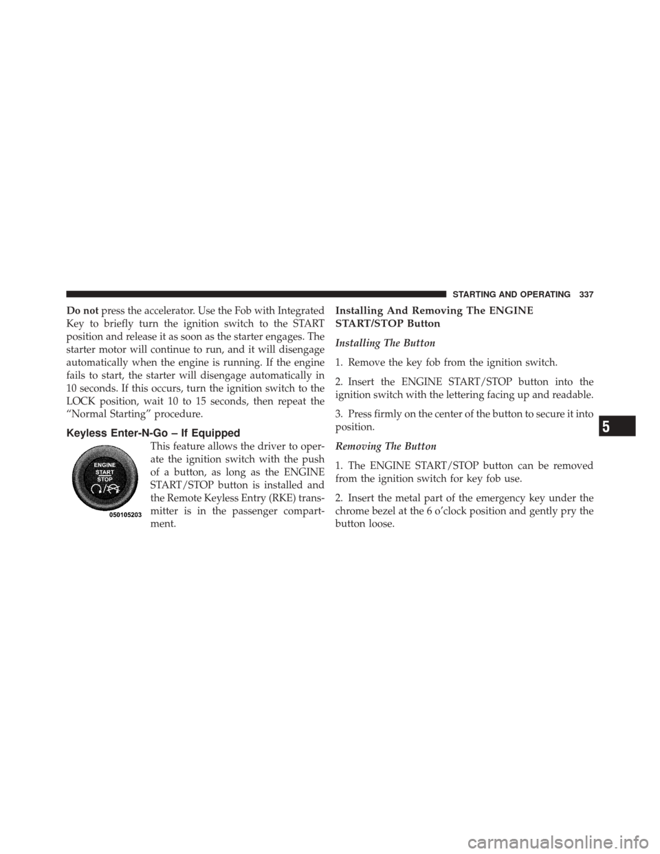
Keyless Enter-N-Go – If Equipped
This feature allows the driver to oper-
ate the ignition switch with the push
of a button, as long as the ENGINE
START/STOP button is installed and
the Remote Keyless Entry (RKE) trans-
mitter is in the passenger compart-
ment.
Installing And Removing The ENGINE
START/STOP Button
Installing The Button
1. Remove the key fob from the ignition switch.
2. Insert the ENGINE START/STOP button into the
ignition switch with the lettering facing up and readable.
3. Press firmly on the center of the button to secure it into
position.
Removing The Button
1. The ENGINE START/STOP button can be removed
from the ignition switch for key fob use.
2. Insert the metal part of the emergency key under the
chrome bezel at the 6 o’clock position and gently pry the
button loose.
5
STARTING AND OPERATING 337
Page 461 of 576
5. Raise the vehicle by turning the jack screw clockwise.
Raise the vehicle just enough to remove the flat tire.
WARNING!
Raising the vehicle higher than necessary can make
the vehicle less stable. It could slip off the jack and
hurt someone near it. Raise the vehicle only enough
to remove the tire.
6. Remove the lug nuts and wheel.
7. Install the spare wheel/tire on the vehicle and install
the lug nuts with the cone-shaped end toward the wheel.
Lightly tighten the nuts.
WARNING!
To avoid the risk of forcing the vehicle off the jack,
do not fully tighten the wheel nuts until the vehicle
has been lowered. Failure to follow this warning may
result in personal injury.
Rear Jacking Location6
WHAT TO DO IN EMERGENCIES 459
Page 462 of 576
8. Lower the vehicle by turning the jack screw counter-
clockwise, and remove the jack and wheel blocks.
9. Finish tightening the lug nuts. Push down on the
wrench while tightening for increased leverage. Alternate
nuts until each nut has been tightened twice. The correct
wheel nut tightness is 110 ft lbs (150 N·m). If in doubt
about the correct tightness, have them checked with a
torque wrench by your authorized dealer or at a service
station.
10. Remove the small center cap and position the alumi-
num road wheel behind rear bumper with the “beauty
side” facing rearward.11. Insert the two long tubes on the plastic protective
plate in the lug holes of the road wheel. Push the end of
the winch’s cable, spring, steel sleeve and stamped cone
shape wheel plate though the road wheel and protective
plate.
“Beauty Side”
460 WHAT TO DO IN EMERGENCIES
Page 463 of 576
12. Slide the road wheel on the ground using the protec-
tive plate until it is directly under the winch and between
the rear bumper and exhaust system heat shields. Raise
the tire by turn the lug wrench on the winch extension
clockwise until it clicks/ratchets three times to make sure
the cable is tight.NOTE:
Double check to ensure the tire is snug against
the underbody of the vehicle. Damage to the winch cable
may result if the vehicle is driven with the tire loose.
Installing WinchRoad Wheel Installed In Spare Location6
WHAT TO DO IN EMERGENCIES 461
Page 464 of 576
WARNING!
Do not use power tools to winch the tire up or down.
Impact-type tools may damage the winch mecha-
nism.
13. Lower the jack to the fully closed position. Return the
tools to the proper positions in the tool bag. Fold the flap
on the tool bag under the tools and roll the tools in the
bag underneath the others. Use the Velcro straps to
secure the tool bag to the jack with the lug wrench on the
forward side of the jack. Expand the jack on the bracket
by turning the thumb screw clockwise until it is tight to
prevent rattles.
14. Reinstall the plastic plug into the floor of the cargo
area. Roll up and store the Jack, Tool Kit and Tire
Changing Instructions. Reinstall the cover for the jack in
the rear storage bin.
Jack And Tool Kit
462 WHAT TO DO IN EMERGENCIES
Page 521 of 576
WARNING!
A transient high tension occurs at the bulb sockets of
High Intensity Discharge (HID) headlamps when the
headlamp switch is turned ON. It may cause serious
electrical shock or electrocution if not serviced prop-
erly. See your authorized dealer for service.
NOTE: On vehicles equipped with High Intensity Dis-
charge (HID) headlamps, when the headlamps are
turned on, there is a blue hue to the lamps. This dimin-
ishes and becomes more white after approximately
10 seconds, as the system charges.
Halogen Headlamps – If Equipped
1. Open the hood.
2. Turn the low or high beam bulb one–quarter turn
counterclockwise to remove from housing. 3. Disconnect the electrical connector and replace the
bulb.
CAUTION!
Do not touch the new bulb with your fingers. Oil
contamination will severely shorten bulb life. If the
bulb comes in contact with any oily surface, clean the
bulb with rubbing alcohol.
Front Turn Signal
1. Open the hood.
2. Turn the turn signal bulb one–quarter turn counter-
clockwise to remove from housing.
3. Disconnect the electrical connector and replace the
bulb.
7
MAINTAINING YOUR VEHICLE 519
Page 524 of 576
4. Twist socket counter clockwise and remove from
lamp.
5. Pull the bulb to remove it from the socket.
6. Replace the bulb, reinstall the socket, and reattach the
lamp assembly.
Rear Liftgate Mounted Tail Lamp
1. Raise the liftgate.
2. Use a fiber stick or flat blade screw driver to pry the
lower trim from the liftgate.
3. Once lower trim is loose, close the liftgate.
4. Open the flipper glass.5. Pull up glass seal at bottom of window opening.
6. Remove small trim panel around liftgate glass striker.
7. Close flipper glass and raise the liftgate.
8. Continue removing the trim.
9. Disconnect the two trim panel lights.
10. Tail lamps are now visible. Rotate socket(s) counter
clockwise.
11. Remove/replace bulb(s).
12. Reinstall the socket(s)
13. Reverse process to reinstall the liftgate trim.
522 MAINTAINING YOUR VEHICLE
Page 558 of 576
Cargo Compartment...................... 225
Light ............................. 226
Luggage Carrier ..................... 230
Cargo Light ............................ 226
Cargo Tie-Downs ........................ 227
Cellular Phone ....................... 1 19,319
Center High Mounted Stop Light ............ 523
Certification Label ....................... 422
Chains, Tire ............................ 397
Changing A Flat Tire ..................... 449
Chart, Tire Sizing ........................ 379
Check Engine Light
(Malfunction Indicator Light) .............262,478
Checking Your Vehicle For Safety ............. 96
Checks, Safety ........................... 96
Child Restraint .................... 82,83,88,90
Child Restraint Tether Anchors .............86,88
Child Safety Locks ........................ 36
Clean Air Gasoline ....................... 411 Climate Control
......................... 319
Clock ............................. 285,294
Cold Weather Operation ................... 339
Compact Disc (CD) Maintenance ............. 318
Compact Spare Tire ...................... 391
Compass .............................. 271
Compass Calibration ..................... 273
Compass Variance ....................... 272
Computer, Trip/Travel .................... 269
Connector UCI .............................. 308
Universal Consumer Interface (UCI) ....... 308
Conserving Fuel ........................ 268
Console, Overhead ....................... 204
Contract, Service ........................ 547
Cooling System ......................... 494
Adding Coolant (Antifreeze) ............. 496
Coolant Capacity ..................... 524
Coolant Level ....................... 498
556 INDEX