radio DODGE DURANGO 2012 3.G Owner's Guide
[x] Cancel search | Manufacturer: DODGE, Model Year: 2012, Model line: DURANGO, Model: DODGE DURANGO 2012 3.GPages: 140, PDF Size: 4.3 MB
Page 72 of 140
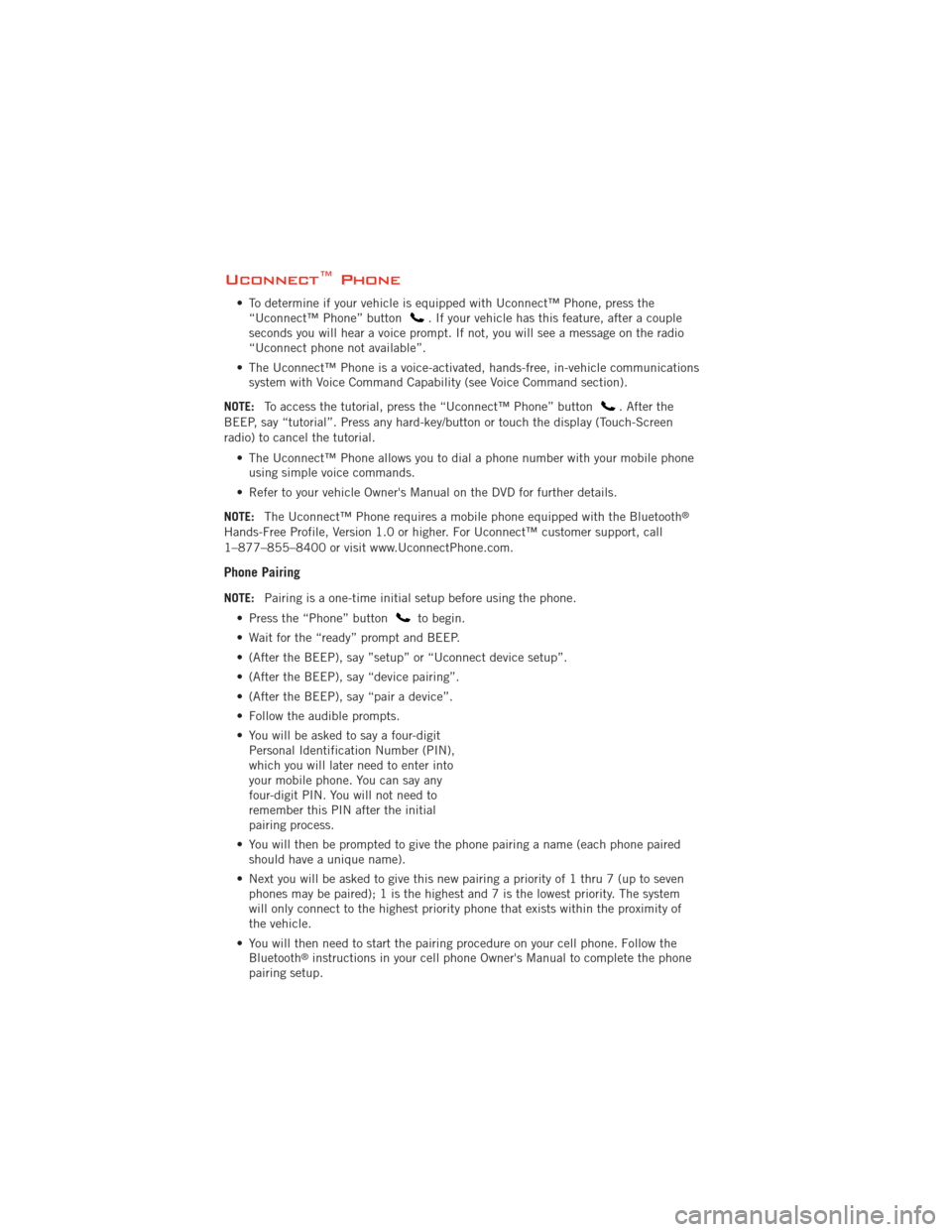
Uconnect™ Phone
• To determine if your vehicle is equipped with Uconnect™ Phone, press the“Uconnect™ Phone” button. If your vehicle has this feature, after a couple
seconds you will hear a voice prompt. If not, you will see a message on the radio
“Uconnect phone not available”.
• The Uconnect™ Phone is a voice-activated, hands-free, in-vehicle communications system with Voice Command Capability (see Voice Command section).
NOTE: To access the tutorial, press the “Uconnect™ Phone” button
. After the
BEEP, say “tutorial”. Press any hard-key/button or touch the display (Touch-Screen
radio) to cancel the tutorial.
• The Uconnect™ Phone allows you to dial a phone number with your mobile phoneusing simple voice commands.
• Refer to your vehicle Owner's Manual on the DVD for further details.
NOTE: The Uconnect™ Phone requires a mobile phone equipped with the Bluetooth
®
Hands-Free Profile, Version 1.0 or higher. For Uconnect™ customer support, call
1–877–855–8400 or visit www.UconnectPhone.com.
Phone Pairing
NOTE:Pairing is a one-time initial setup before using the phone.
• Press the “Phone” button
to begin.
• Wait for the “ready” prompt and BEEP.
• (After the BEEP), say ”setup” or “Uconnect device setup”.
• (After the BEEP), say “device pairing”.
• (After the BEEP), say “pair a device”.
• Follow the audible prompts.
• You will be asked to say a four-digit Personal Identification Number (PIN),
which you will later need to enter into
your mobile phone. You can say any
four-digit PIN. You will not need to
remember this PIN after the initial
pairing process.
• You will then be prompted to give the phone pairing a name (each phone paired should have a unique name).
• Next you will be asked to give this new pairing a priority of 1 thru 7 (up to seven phones may be paired); 1 is the highest and 7 is the lowest priority. The system
will only connect to the highest priority phone that exists within the proximity of
the vehicle.
• You will then need to start the pairing procedure on your cell phone. Follow the Bluetooth
®instructions in your cell phone Owner's Manual to complete the phone
pairing setup.
ELECTRONICS
70
Page 74 of 140
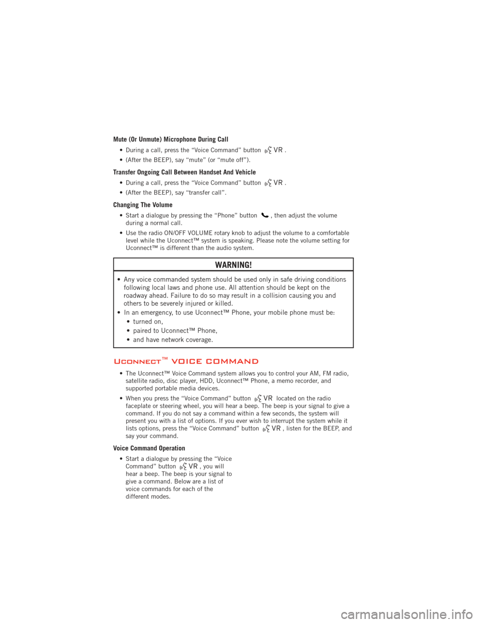
Mute (Or Unmute) Microphone During Call
• During a call, press the “Voice Command” button.
• (After the BEEP), say “mute” (or “mute off”).
Transfer Ongoing Call Between Handset And Vehicle
• During a call, press the “Voice Command” button.
• (After the BEEP), say “transfer call”.
Changing The Volume
• Start a dialogue by pressing the “Phone” button, then adjust the volume
during a normal call.
• Use the radio ON/OFF VOLUME rotary knob to adjust the volume to a comfortable level while the Uconnect™ system is speaking. Please note the volume setting for
Uconnect™ is different than the audio system.
WARNING!
• Any voice commanded system should be used only in safe driving conditionsfollowing local laws and phone use. All attention should be kept on the
roadway ahead. Failure to do so may result in a collision causing you and
others to be severely injured or killed.
• In an emergency, to use Uconnect™ Phone, your mobile phone must be: • turned on,
• paired to Uconnect™ Phone,
• and have network coverage.
Uconnect™ VOICE COMMAND
• The Uconnect™ Voice Command system allows you to control your AM, FM radio,satellite radio, disc player, HDD, Uconnect™ Phone, a memo recorder, and
supported portable media devices.
• When you press the “Voice Command” button
located on the radio
faceplate or steering wheel, you will hear a beep. The beep is your signal to give a
command. If you do not say a command within a few seconds, the system will
present you with a list of options. If you ever wish to interrupt the system while it
lists options, press the “Voice Command” button
, listen for the BEEP, and
say your command.
Voice Command Operation
• Start a dialogue by pressing the “Voice Command” button, you will
hear a beep. The beep is your signal to
give a command. Below are a list of
voice commands for each of the
different modes.
ELECTRONICS
72
Page 75 of 140
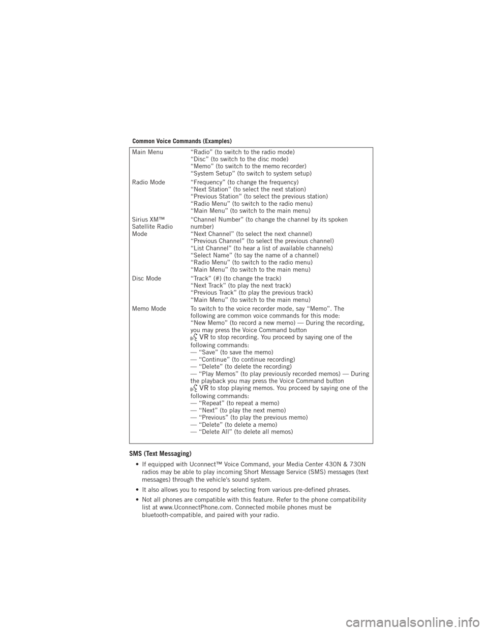
Common Voice Commands (Examples)
Main Menu “Radio” (to switch to the radio mode)“Disc” (to switch to the disc mode)
“Memo” (to switch to the memo recorder)
“System Setup” (to switch to system setup)
Radio Mode “Frequency” (to change the frequency) “Next Station” (to select the next station)
“Previous Station” (to select the previous station)
“Radio Menu” (to switch to the radio menu)
“Main Menu” (to switch to the main menu)
Sirius XM™
Satellite Radio
Mode “Channel Number” (to change the channel by its spoken
number)
“Next Channel” (to select the next channel)
“Previous Channel” (to select the previous channel)
“List Channel” (to hear a list of available channels)
“Select Name” (to say the name of a channel)
“Radio Menu” (to switch to the radio menu)
“Main Menu” (to switch to the main menu)
Disc Mode “Track” (#) (to change the track) “Next Track” (to play the next track)
“Previous Track” (to play the previous track)
“Main Menu” (to switch to the main menu)
Memo Mode To switch to the voice recorder mode, say “Memo”. The following are common voice commands for this mode:
“New Memo” (to record a new memo) — During the recording,
you may press the Voice Command button
to stop recording. You proceed by saying one of the
following commands:
— “Save” (to save the memo)
— “Continue” (to continue recording)
— “Delete” (to delete the recording)
— “Play Memos” (to play previously recorded memos) — During
the playback you may press the Voice Command button
to stop playing memos. You proceed by saying one of the
following commands:
— “Repeat” (to repeat a memo)
— “Next” (to play the next memo)
— “Previous” (to play the previous memo)
— “Delete” (to delete a memo)
— “Delete All” (to delete all memos)
SMS (Text Messaging)
• If equipped with Uconnect™ Voice Command, your Media Center 430N & 730N radios may be able to play incoming Short Message Service (SMS) messages (text
messages) through the vehicle's sound system.
• It also allows you to respond by selecting from various pre-defined phrases.
• Not all phones are compatible with this feature. Refer to the phone compatibility list at www.UconnectPhone.com. Connected mobile phones must be
bluetooth-compatible, and paired with your radio.
ELECTRONICS
73
Page 76 of 140
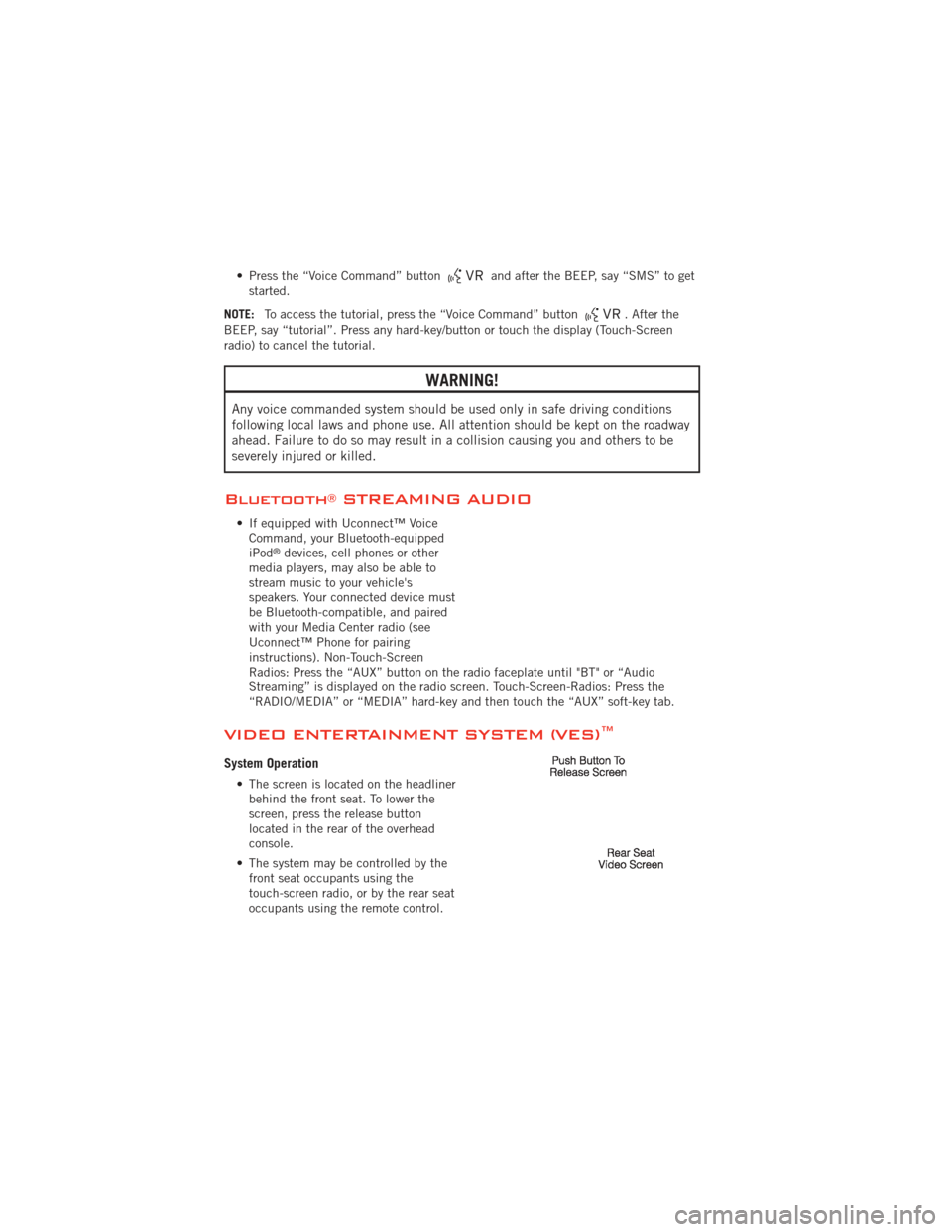
• Press the “Voice Command” buttonand after the BEEP, say “SMS” to get
started.
NOTE: To access the tutorial, press the “Voice Command” button
. After the
BEEP, say “tutorial”. Press any hard-key/button or touch the display (Touch-Screen
radio) to cancel the tutorial.
WARNING!
Any voice commanded system should be used only in safe driving conditions
following local laws and phone use. All attention should be kept on the roadway
ahead. Failure to do so may result in a collision causing you and others to be
severely injured or killed.
Bluetooth®STREAMING AUDIO
• If equipped with Uconnect™ Voice Command, your Bluetooth-equipped
iPod
®devices, cell phones or other
media players, may also be able to
stream music to your vehicle's
speakers. Your connected device must
be Bluetooth-compatible, and paired
with your Media Center radio (see
Uconnect™ Phone for pairing
instructions). Non-Touch-Screen
Radios: Press the “AUX” button on the radio faceplate until "BT" or “Audio
Streaming” is displayed on the radio screen. Touch-Screen-Radios: Press the
“RADIO/MEDIA” or “MEDIA” hard-key and then touch the “AUX” soft-key tab.
VIDEO ENTERTAINMENT SYSTEM (VES)™
System Operation
• The screen is located on the headliner behind the front seat. To lower the
screen, press the release button
located in the rear of the overhead
console.
• The system may be controlled by the front seat occupants using the
touch-screen radio, or by the rear seat
occupants using the remote control.
ELECTRONICS
74
Page 77 of 140
• The video screen displays information in a split-screen format. The left side of thescreen is referred to as Channel 1 and the right side of the screen is referred to as
Channel 2. All modes except video modes are displayed in a split-screen format.
• To use the headphones, press the power button located on the right ear cup. Select the channel on the headphones (1 or 2) that corresponds to the channel selected
on the VES™ screen.
Operation Of The Touch-Screen Radio
• To view a DVD video, press the OPEN/CLOSE or LOAD hard-key and insert the disc.Playback will begin automatically after the DVD is recognized by the disc drive. If
playback does not begin automatically, follow these steps:
• Press the MENU hard-key, then touch the Rear VES™ soft-key. If a chapter list appears on the right side of the screen touch the HIDE LIST soft-key to display
the Rear VES™ Control screen.
• Touch the 1 soft-key to select an audio channel, then touch the DISC soft-key in the MEDIA column.
Operation Of The Remote
• The remote control operates similarly to any DVD remote you have used before andallows the rear seat passengers to change stations, tracks, discs and audio/video
modes.
• The remote control is designed to control either channel by using the selector switch located on the right side of the remote.
• Pressing the power button will turn the VES™ system ON/OFF.
• Pressing the MODE button causes the Mode Selection menu to appear on the VES™ screen. Use the remote control arrow buttons to scroll through the available
modes, then press ENTER to select the desired mode.
Auxiliary Audio/Video Input Jacks
• The Aux jacks are located on the rear of the center console.
• Connect the video game or other external media devices to the AUX jacks followingthe color coding for VES™ jacks.
• Using either the touch-screen radio or remote control, select AUX from the Rear VES™ Control or Mode Selection screen.
• Refer to your vehicle's Owners Manual on the DVD for further details.
ELECTRONICS
75
Page 80 of 140
Before You Begin Programming HomeLink®
• Be sure that your vehicle is parkedoutside of the garage before you begin
programming.
• For more efficient programming and accurate transmission of the
radio-frequency signal it is
recommended that a new battery be
placed in the hand-held transmitter of
the device that is being programmed to
the HomeLink
®system.
• Erase all channels before you begin programming. To erase the channels, place the ignition switch into the ON/RUN position, then press and hold the two outside
HomeLink
®buttons (I and III) for up 20 seconds or until the red indicator flashes.
NOTE:
• Erasing all channels should only be performed when programming HomeLink
®for the
first time. Do not erase channels when programming additional buttons.
• If you have any problems, or require assistance, please call toll-free 1–800–355– 3515 or, on the Internet at www.HomeLink.com for information or assistance.
Programming A Rolling Code
• For programming Garage Door Openers that were manufactured after 1995. TheseGarage Door Openers can be identified by the “LEARN” or “TRAIN” button located
where the hanging antenna is attached to the Garage Door Opener. It is NOT the
button that is normally used to open and close the door. The name and color of the
button may vary by manufacturer.
• Place the ignition switch into the ON/RUN position.
• Place the hand-held transmitter 1 to 3 in (3 to 8 cm) away from the HomeLink
®
button you wish to program while keeping the HomeLink®indicator light in view.
• Simultaneously press and hold both the HomeLink
®button you want to program
and the hand-held transmitter button.
• Continue to hold both buttons and observe the indicator light. The Homelink
®
indicator will flash slowly and then rapidly after Homelink®has received the
frequency signal from the hand-held transmitter. Release both buttons after the
indicator light changes from slow to rapid.
• At the garage door opener motor (in the garage), locate the “LEARN” or “TRAINING” button. This can usually be found where the hanging antenna wire is
attached to the garage door opener motor. Firmly press and release the “LEARN”
or “TRAINING” button.
NOTE: You have 30 seconds in which to initiate the next step after the LEARN button
has been pressed.
ELECTRONICS
78
Page 105 of 140
BATTERY LOCATION
• The battery in your vehicle is located under the passenger's front seat. Remotebattery posts are located on the right side of the engine compartment for
jump-starting.
JUMP-STARTING
• If your vehicle has a discharged battery it can be jump-started using a set ofjumper cables and a battery in another vehicle or by using a portable battery
booster pack.
• Jump-starting can be dangerous if done improperly so please follow the procedures in this section carefully.
NOTE: When using a portable battery booster pack follow the manufacturer’s operating
instructions and precautions.
Preparations for Jump-Start
• The battery in your vehicle is located under the passengers front seat. There
are remote locations under the hood to
assist in jump starting.
• Set the parking brake, shift the automatic transmission into PARK and
turn the ignition to OFF.
• Turn off the heater, radio, and all unnecessary electrical accessories.
• Remove the protective cover over the remote positive (+) battery post. Pull
upward on the cover to remove it.
• If using another vehicle to jump-start the battery, park the vehicle within the jumper cables reach, set the parking brake and make sure the ignition is OFF.
Jump-Starting Procedure
• Connect the positive (+)end of the jumper cable to the remote positive (+)post of
the discharged vehicle.
• Connect the opposite end of the positive (+)jumper cable to the positive (+)post
of the booster battery.
• Remove the protective cap from the negative jump post. Connect the negative end (-) of the jumper cable to the negative (-)post of the booster battery.
• Connect the opposite end of the negative (-)jumper cable to the remote negative
(-) post of the vehicle with the discharged battery.
WHAT TO DO IN EMERGENCIES
103
Page 122 of 140
Cavity Cartridge Fuse Mini FuseDescription
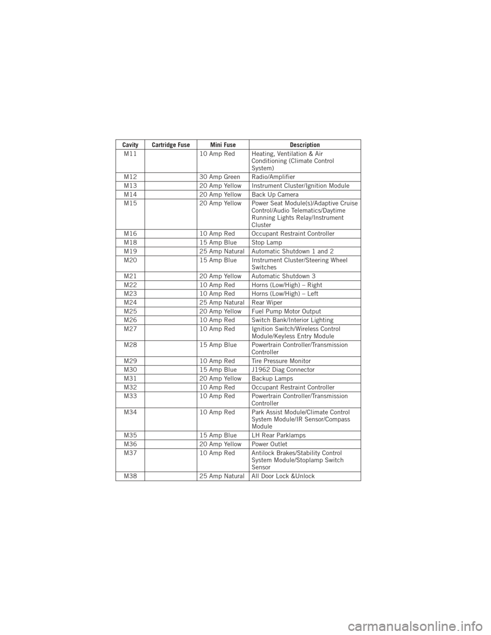
M11 10 Amp Red Heating, Ventilation & Air
Conditioning (Climate Control
System)
M12 30 Amp Green Radio/Amplifier
M13 20 Amp Yellow Instrument Cluster/Ignition Module
M14 20 Amp Yellow Back Up Camera
M15 20 Amp Yellow Power Seat Module(s)/Adaptive Cruise
Control/Audio Telematics/Daytime
Running Lights Relay/Instrument
Cluster
M16 10 Amp Red Occupant Restraint Controller
M18 15 Amp Blue Stop Lamp
M19 25 Amp Natural Automatic Shutdown 1 and 2
M20 15 Amp Blue Instrument Cluster/Steering Wheel
Switches
M21 20 Amp Yellow Automatic Shutdown 3
M22 10 Amp Red Horns (Low/High) – Right
M23 10 Amp Red Horns (Low/High) – Left
M24 25 Amp Natural Rear Wiper
M25 20 Amp Yellow Fuel Pump Motor Output
M26 10 Amp Red Switch Bank/Interior Lighting
M27 10 Amp Red Ignition Switch/Wireless Control
Module/Keyless Entry Module
M28 15 Amp Blue Powertrain Controller/Transmission
Controller
M29 10 Amp Red Tire Pressure Monitor
M30 15 Amp Blue J1962 Diag Connector
M31 20 Amp Yellow Backup Lamps
M32 10 Amp Red Occupant Restraint Controller
M33 10 Amp Red Powertrain Controller/Transmission
Controller
M34 10 Amp Red Park Assist Module/Climate Control
System Module/IR Sensor/Compass
Module
M35 15 Amp Blue LH Rear Parklamps
M36 20 Amp Yellow Power Outlet
M37 10 Amp Red Antilock Brakes/Stability Control
System Module/Stoplamp Switch
Sensor
M38 25 Amp Natural All Door Lock &Unlock
MAINTAINING YOUR VEHICLE
120
Page 125 of 140
CHRYSLER GROUP LLC CUSTOMER CENTER
P.O. Box 21–8004
Auburn Hills, MI 48321–8004
Phone: 1–800–423–6343
CHRYSLER CANADA INC. CUSTOMER CENTER
P.O. Box 1621
Windsor, Ontario N9A 4H6
Phone: 1–800–465–2001 (English)
Phone: 1–800–387–9983 (French)
ASSISTANCE FOR THE HEARING IMPAIRED
• To assist customers who have hearing difficulties, the manufacturer has installedspecial TDD (Telecommunication Devices for the Deaf) equipment at its customer
center. Any hearing or speech impaired customer, who has access to a TDD or a
conventional teletypewriter (TTY) in the United States, can communicate with the
manufacturer by dialing 1–800–380–CHRY. Canadian residents with hearing
difficulties that require assistance can use the special needs relay service offered
by Bell Canada. For TTY teletypewriter users, dial 711 and for Voice callers, dial
1–800–855–0511 to connect with a Bell Relay Service operator.
WARNING!
Engine exhaust, some of its constituents, and certain vehicle components
contain, or emit, chemicals known to the State of California to cause cancer
and birth defects, or other reproductive harm. In addition, certain fluids
contained in vehicles and certain products of component wear contain, or emit,
chemicals known to the State of California to cause cancer and birth defects, or
other reproductive harm.
PUBLICATIONS ORDERING
•If you are the first registered retail owner of your vehicle, you may obtain one free
printed copy of the Owner's Manual, Warranty Booklet or Radio Manuals on your
DVD by calling 1–800–423–6343 (U.S.) or 1–800–387–1143 (Canada) or by
contacting your dealer.
• Replacement User Guide kits or DVDs or, if you prefer, additional printed copies of the Owner's Manual, Warranty Booklet or Radio Manuals may be purchased by
visiting www.techauthority.com or by calling 1–800–890–4038 (U.S.) or
1–800–387–1143 (Canada). Visa, Master Card, American Express and Discover
orders are accepted. If you prefer mailing your order, please call the above
numbers for an order form.
NOTE: A street address is required when ordering manuals (no P.O. Boxes).
CONSUMER ASSISTANCE
123
Page 129 of 140
Fluid Capacities............ 113
Fluids ................. 113
FogLights ................ 27
Folding Front Passenger Seat ..... 21
Folding Power Third Row
Head Restraints ............ 23
FoldingRearSeat ......... 21,22
Four Wheel Drive ............ 83
Operation ............... 83
Systems ................ 83
Four Wheel Drive Operation ...... 83
Front Heated Seats ........... 23
Fuel Filler Cap (Gas Cap) ......... 92
Filler Door (Gas Cap) ....... 109
Filler Door Emergency Release . . 110
Specifications ........113,114
Fuses .................. 118
Garage Door Opener (HomeLink
®)..77
Gas Cap (Fuel Filler Cap) ....... 92
Head Restraints Power Folding Third Row ...... 23
Headlights ............... 27 Automatic .............. 27
Dimmer Switch ........... 28
HighBeam .............. 29
High Beam/Low Beam Select
Switch ................ 29
Heated Mirrors ............. 35
Heated Seats .............. 23
Heated Steering Wheel ........ 25
High Beam/Low Beam Select
(Dimmer) Switch ............ 29
HomeLink
®(Garage Door Opener)
Transmitter ............... 77
Hood Release ............. 109
Instrument Cluster ............ 6
Indicators ............... 7
Instrument Cluster Warning
Lights ................. 6,89
Integrated Power Module (Fuses) . . 119
Intermittent Wipers (Delay Wipers) . . 28
Introduction ............... 2
Inverter Outlet (115V) ......... 80Inverter, Power
............. 80
iPod
®/USB/MP3 Control ........ 68
Bluetooth Streaming Audio ..... 74
Jack Location .............. 94
Jack Operation ........... 94,97
Jacking Instructions .......... 97
Jump Starting ............. 103
KeyFob .................. 8
Keyless Enter-N-Go™ ......... 11
Lock/Unlock ........... 11,12
Starting/Stopping .......... 13
Lane Change Assist .......... 28
LATCH (Lower Anchors and Tether for
CHildren) ................ 16
Liftgate, Power .............. 8
LightBulbs .............. 122
Lights Warning (Instrument Cluster
Description) .............. 6
Luggage Rack (Roof Rack) ...... 85
Maintenance Record ......... 117
MaintenanceSchedule ........ 115
Malfunction Indicator Light (Check
Engine) ................. 90
MediaCenterRadio ........ 42,44
MemorySeat .............. 19
Mirrors Automatic Dimming ......... 29
Heated ................ 35
MOPAR
®Accessories ........ 125
Navigation .............. 52,61
New Vehicle Break-In Period ..... 27
Oil Change Indicator .......... 92
Oil Change Indicator, Reset ...... 92
Oil Pressure Light ........... 91
Oil, Engine Capacity ............... 113
Outlet Power ................. 81
INDEX
127