engine DODGE DURANGO 2012 3.G User Guide
[x] Cancel search | Manufacturer: DODGE, Model Year: 2012, Model line: DURANGO, Model: DODGE DURANGO 2012 3.GPages: 140, PDF Size: 4.3 MB
Page 3 of 140
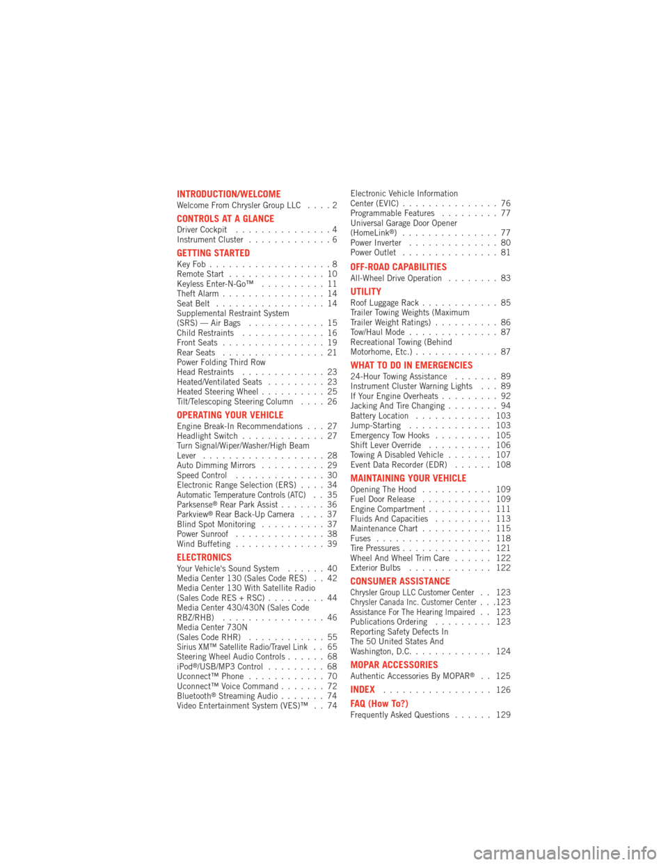
INTRODUCTION/WELCOMEWelcome From Chrysler Group LLC....2
CONTROLS AT A GLANCEDriver Cockpit...............4
Instrument Cluster .............6
GETTING STARTEDKeyFob...................8
Remote Start...............10
Keyless Enter-N-Go™ ..........11
Theft Alarm ................14
Seat Belt .................14
Supplemental Restraint System
(SRS) — Air Bags ............15
Child Restraints .............16
Front Seats ................19
Rear Seats ................21
Power Folding Third Row
Head Restraints .............23
Heated/Ventilated Seats .........23
Heated Steering Wheel ..........25
Tilt/Telescoping Steering Column ....26
OPERATING YOUR VEHICLEEngine Break-In Recommendations . . . 27
Headlight Switch.............27
Turn Signal/Wiper/Washer/High Beam
Lever ...................28
Auto Dimming Mirrors ..........29
Speed Control ..............30
Electronic Range Selection (ERS) ....34
Automatic Temperature Controls (ATC).. 35
Parksense®Rear Park Assist .......36
Parkview®Rear Back-Up Camera ....37
Blind Spot Monitoring ..........37
Power Sunroof ..............38
Wind Buffeting ..............39
ELECTRONICSYour Vehicle's Sound System ......40
Media Center 130 (Sales Code RES) . . 42
Media Center 130 With Satellite Radio
(Sales Code RES + RSC) .........44
Media Center 430/430N (Sales Code
RBZ/RHB) ................46
Media Center 730N
(Sales Code RHR) ............55
Sirius XM™ Satellite Radio/Travel Link.. 65
Steering Wheel Audio Controls ......68
iPod
®/USB/MP3 Control .........68
Uconnect™ Phone ............70
Uconnect™ Voice Command .......72
Bluetooth
®Streaming Audio .......74
Video Entertainment System (VES)™ . . 74 Electronic Vehicle Information
Center (EVIC)
...............76
Programmable Features .........77
Universal Garage Door Opener
(HomeLink
®) ...............77
Power Inverter ..............80
Power Outlet ...............81
OFF-ROAD CAPABILITIESAll-Wheel Drive Operation ........83
UTILITYRoof Luggage Rack............85
Trailer Towing Weights (Maximum
Trailer Weight Ratings) ..........86
Tow/Haul Mode ..............87
Recreational Towing (Behind
Motorhome, Etc.) .............87
WHAT TO DO IN EMERGENCIES24-Hour Towing Assistance .......89
Instrument Cluster Warning Lights . . . 89
If Your Engine Overheats .........92
Jacking And Tire Changing ........94
Battery Location ............ 103
Jump-Starting ............. 103
Emergency Tow Hooks ......... 105
Shift Lever Override .......... 106
Towing A Disabled Vehicle ....... 107
Event Data Recorder (EDR) ...... 108
MAINTAINING YOUR VEHICLEOpening The Hood........... 109
Fuel Door Release ........... 109
Engine Compartment .......... 111
Fluids And Capacities ......... 113
Maintenance Chart ........... 115
Fuses .................. 118
Tire Pressures .............. 121
Wheel And Wheel Trim Care ...... 122
Exterior Bulbs ............. 122
CONSUMER ASSISTANCEChrysler Group LLC Customer Center. . 123Chrysler Canada Inc. Customer Center...123Assistance For The Hearing Impaired. . 123
Publications Ordering ......... 123
Reporting Safety Defects In
The 50 United States And
Washington, D.C. ............ 124
MOPAR ACCESSORIESAuthentic Accessories By MOPAR®. . 125
INDEX................. 126
FAQ (How To?)Frequently Asked Questions ...... 129
TABLE OF CONTENTS
Page 8 of 140
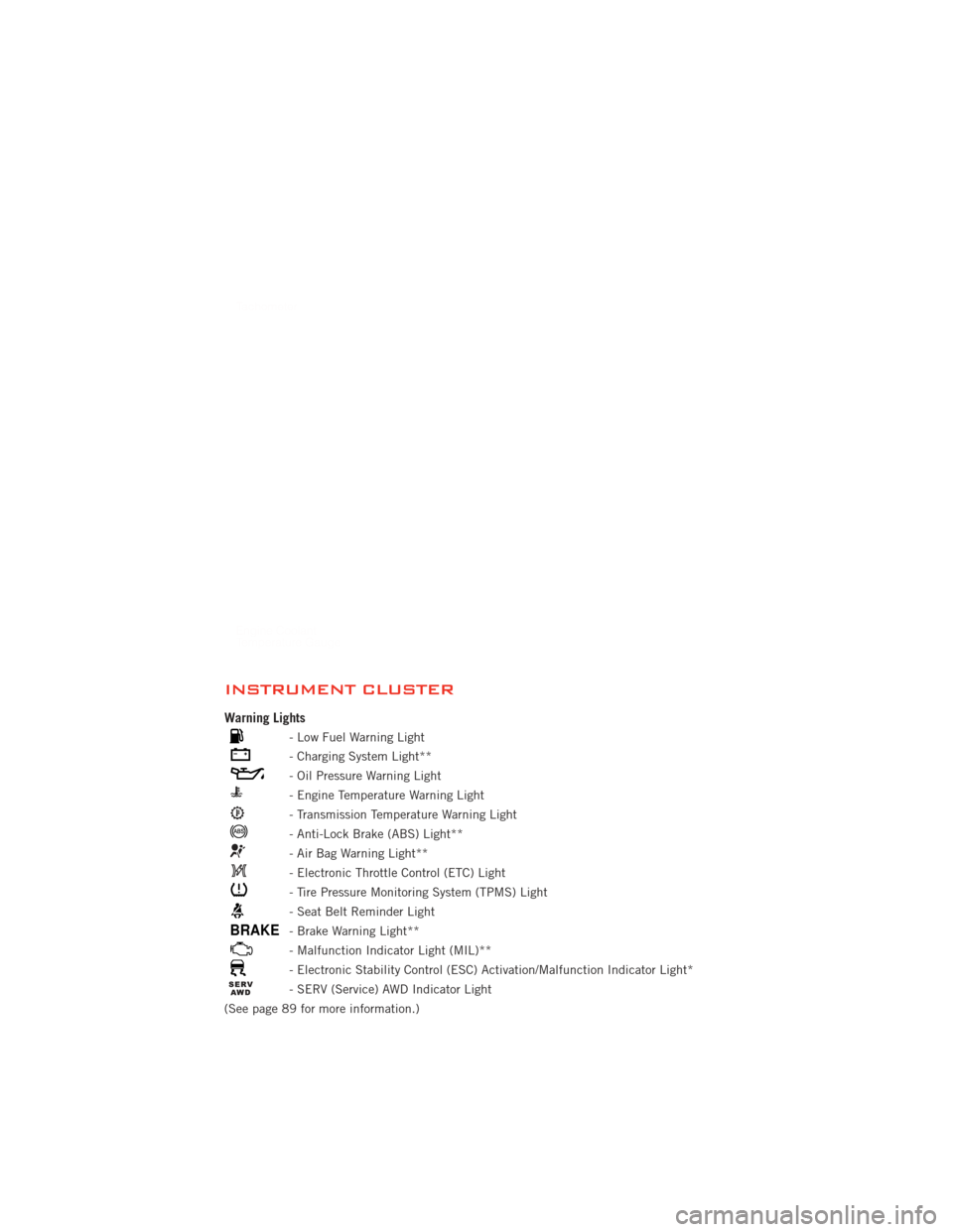
INSTRUMENT CLUSTER
Warning Lights
- Low Fuel Warning Light
- Charging System Light**
- Oil Pressure Warning Light
- Engine Temperature Warning Light
- Transmission Temperature Warning Light
- Anti-Lock Brake (ABS) Light**
- Air Bag Warning Light**
- Electronic Throttle Control (ETC) Light
- Tire Pressure Monitoring System (TPMS) Light
- Seat Belt Reminder Light
BRAKE- Brake Warning Light**
- Malfunction Indicator Light (MIL)**
- Electronic Stability Control (ESC) Activation/Malfunction Indicator Light*
- SERV (Service) AWD Indicator Light
(See page 89 for more information.)
CONTROLS AT A GLANCE
6
Page 11 of 140
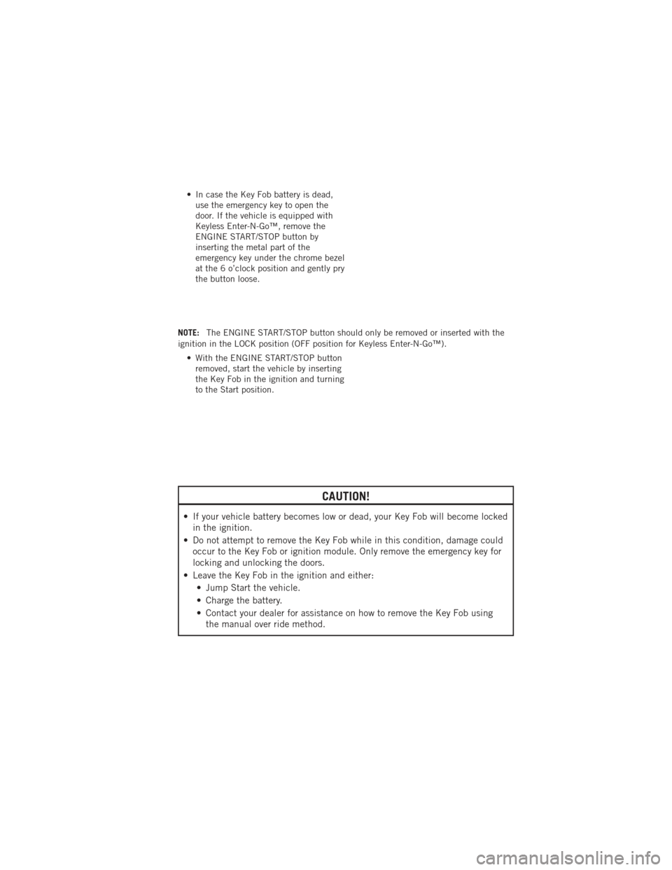
• In case the Key Fob battery is dead,use the emergency key to open the
door. If the vehicle is equipped with
Keyless Enter-N-Go™, remove the
ENGINE START/STOP button by
inserting the metal part of the
emergency key under the chrome bezel
at the 6 o’clock position and gently pry
the button loose.
NOTE: The ENGINE START/STOP button should only be removed or inserted with the
ignition in the LOCK position (OFF position for Keyless Enter-N-Go™).
• With the ENGINE START/STOP buttonremoved, start the vehicle by inserting
the Key Fob in the ignition and turning
to the Start position.
CAUTION!
• If your vehicle battery becomes low or dead, your Key Fob will become lockedin the ignition.
• Do not attempt to remove the Key Fob while in this condition, damage could occur to the Key Fob or ignition module. Only remove the emergency key for
locking and unlocking the doors.
• Leave the Key Fob in the ignition and either: • Jump Start the vehicle.
• Charge the battery.
• Contact your dealer for assistance on how to remove the Key Fob usingthe manual over ride method.
GETTING STARTED
9
Page 12 of 140
WARNING!
• Leaving unattended children in a vehicle is dangerous for a number ofreasons. A child or others could be severely injured or killed. Children should
be warned not to touch the parking brake, brake pedal, or the shift lever. Do
not leave the Key Fob inside the vehicle or in the ignition. A child could start
the vehicle, operate power windows, other controls, or move the vehicle.
• Do not leave children or animals inside parked vehicles in hot weather. Interior heat build-up may cause them to be severely injured or killed.
• Keep Key Fob transmitters away from children. Operation of the Remote Start System, windows, door locks or other controls could cause serious injury or
death.
• Driving with the liftgate open can allow poisonous exhaust gases into your vehicle. You and your passengers could be injured by these fumes. Keep the
flipper glass closed when you are operating the vehicle.
REMOTE START
• Press the REMOTE START buttonx2on the Key Fob twice within five seconds.
Pressing the REMOTE START button a third time shuts the engine off.
• To drive the vehicle, with a valid Keyless Enter-N-Go™ Key Fob within 5 ft (1.5 m) of the driver's side of the vehicle, grab the front driver door handle to unlock the
driver's door automatically, then press the Start/Stop switch. Or press the UNLOCK
button, insert the Key Fob in the ignition and turn to the ON/RUN position.
• With remote start, the engine will only run for 15 minutes (timeout) unless the ignition is placed in the ON/RUN position.
• The vehicle must be started with the Key Fob after two consecutive timeouts.
WARNING!
• Do not start or run an engine in a closed garage or confined area. Exhaust gas contains Carbon Monoxide (CO) which is odorless and colorless. Carbon
Monoxide is poisonous and can cause you or others to be severely injured or
killed when inhaled.
• Keep Key Fob transmitters away from children. Operation of the Remote Start System, windows, door locks or other controls could cause you and others to
be severely injured or killed.
GETTING STARTED
10
Page 14 of 140
• If a Key Fob is detected in the vehicle when locking the vehicle using the power doorlock switch, the doors and liftgate will unlock and the horn will chirp three times. On
the third attempt, your Key Fob can be locked inside the vehicle.
• After pressing the Keyless Enter-N-Go™ LOCK button, you must wait 2 seconds before you can lock or unlock the vehicle using the door handle. This is done to allow
you to check if the vehicle is locked by pulling the door handle, without the vehicle
reacting and unlocking.
• If a Keyless Enter-N-Go™ door handle has not been used for 72 hours, the Keyless Enter-N-Go™ feature for that handle may time out. Pulling the deactivated front door
handle will reactivate the door handle's Keyless Enter-N-Go™ feature.
Lock or Unlock the Liftgate:
• With a valid Keyless Enter-N-Go™ KeyFob within 3 ft (1.0 m) of the liftgate,
press the button located to the right of
the liftgate handle to unlock the
liftgate. Press the button a second
time to lock the liftgate.
NOTE:
• Refer to your Owner's Manual on the DVD for further information.
Installing And Removing The ENGINE START/STOP Button
Installing The Button
• Remove the Key Fob from the ignition switch.
• Insert the ENGINE START/STOP button into the ignition switch with the lettering facing up and readable.
• Press firmly on the center of the button to secure it into position.
Removing The Button • The ENGINE START/STOP button can be removed from the ignition switch for Key Fob use.
• Insert the metal part of the emergency key under the chrome bezel at the 6 o’clock position and gently pry the button
loose.
NOTE:
• The ENGINE START/STOP button should only be removed or inserted with the
ignition in the LOCK position (OFF
position for Keyless Enter-N-Go™).
GETTING STARTED
12
Page 15 of 140
Engine Starting/Stopping
Starting• With a valid Keyless Enter-N-Go™ Key Fob inside the vehicle.
• Place the shift lever in PARK or NEUTRAL.
• While pressing the brake pedal, press the ENGINE START/STOP button once.
If the engine fails to start, the starter
will disengage automatically after
10 seconds.
• To stop the cranking of the engine prior to the engine starting, press the button again.
Stopping • Place the shift lever in PARK.
• Press the ENGINE START/STOP button once. The ignition switch will return to the OFF position.
• If the shift lever is not in PARK, the ENGINE START/STOP button must be held for two
seconds and vehicle speed must be above 5 mph (8 km/h) before the engine will shut
off.
Accessory Positions with Engine Off
NOTE:
• The following functions are with the driver’s foot OFF the Brake Pedal (Transmission
in PARK or NEUTRAL Position).
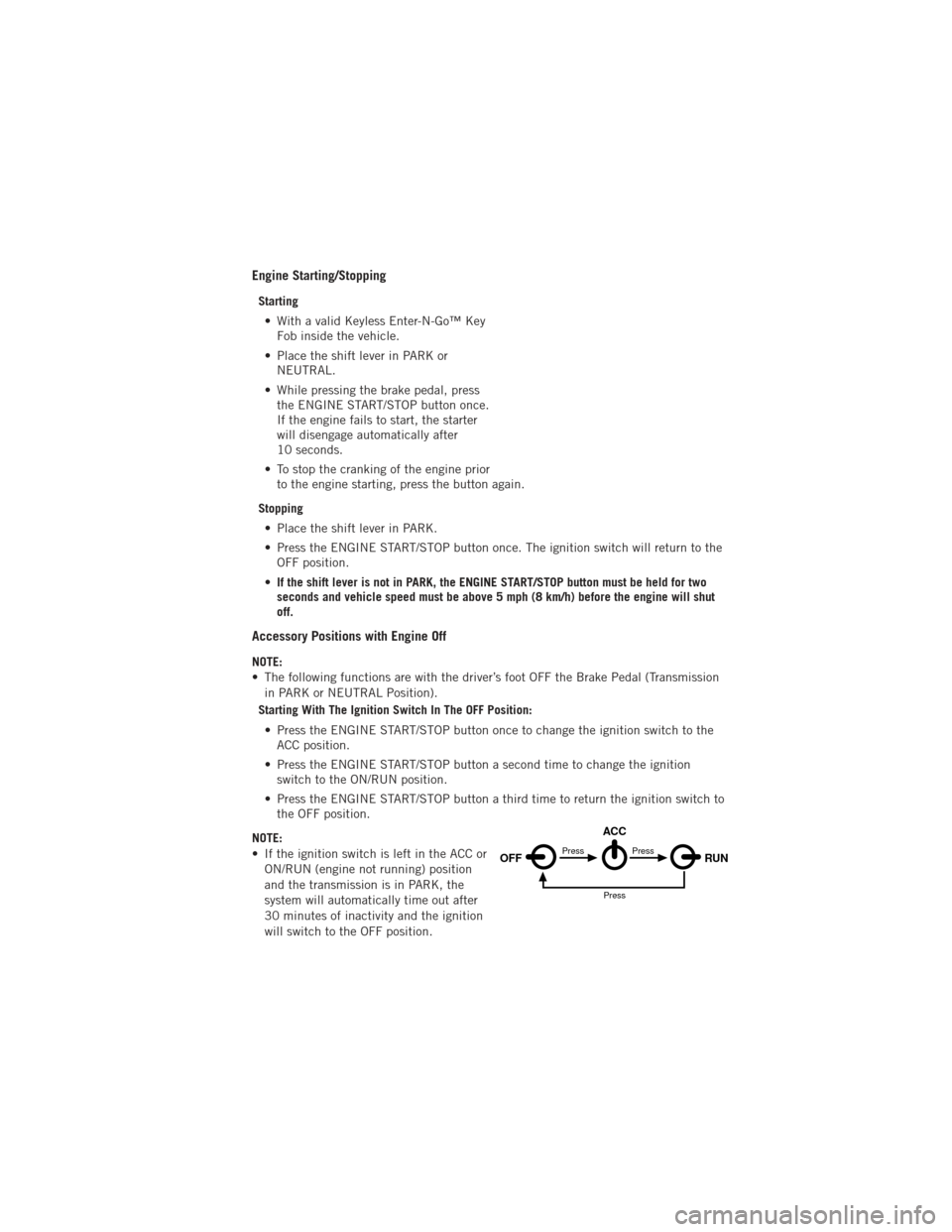
Starting With The Ignition Switch In The OFF Position:
• Press the ENGINE START/STOP button once to change the ignition switch to the ACC position.
• Press the ENGINE START/STOP button a second time to change the ignition switch to the ON/RUN position.
• Press the ENGINE START/STOP button a third time to return the ignition switch to the OFF position.
NOTE:
• If the ignition switch is left in the ACC or ON/RUN (engine not running) position
and the transmission is in PARK, the
system will automatically time out after
30 minutes of inactivity and the ignition
will switch to the OFF position.
OFF RUN
ACCPress
Press
Press
GETTING STARTED
13
Page 29 of 140
ENGINE BREAK-IN RECOMMENDATIONS
• A long break-in period is not required for the engine and drivetrain (transmissionand axle) in your vehicle.
• Drive moderately during the first 300 miles (500 km). After the initial 60 miles (100 km), speeds up to 50 or 55 mph (80 or 90 km/h) are desirable.
• While cruising, brief full-throttle acceleration within the limits of local traffic laws contributes to a good break-in. Wide-open throttle acceleration in low gear can be
detrimental and should be avoided.
• The engine oil installed in the engine at the factory is a high-quality energy conserving type lubricant. Oil changes should be consistent with anticipated
climate conditions under which vehicle operations will occur. For the
recommended viscosity and quality grades, refer to “Maintaining Your Vehicle”.
NOTE: A new engine may consume some oil during its first few thousand miles
(kilometers) of operation. This should be considered a normal part of the break-in and
not interpreted as an indication of difficulty.
CAUTION!
Never use Non-Detergent Oil or Straight Mineral Oil in the engine or damage
may result.
HEADLIGHT SWITCH
Automatic Headlights/Parking
Lights/Headlights
• Rotate the headlight switch, located on the instrument panel to the left of the
steering wheel, to the first detent for
parking lights
andtothe
second detent for headlights.
• With the parking lights or low beam headlights on, push the headlight
switch once for fog lights.
• Rotate the headlight switch to “AUTO” for AUTO headlights.
• When set to AUTO, the system automatically turns the headlights on
or off based on ambient light levels.
SmartBeams™
• This system automatically controls the use of the headlight high beams. Refer toProgrammable Features in Electronics for further details.
OPERATING YOUR VEHICLE
27
Page 36 of 140
ELECTRONIC RANGE SELECTION (ERS)
• Electronic Range Select (ERS) allowsyou to limit the highest available
transmission gear, and can be
activated during any driving condition.
When towing a trailer, using ERS shift
control will help you maximize both
performance and engine braking.
• To switch from DRIVE mode to ERS mode, tap the shift lever to the left (-) once. The instrument cluster will display the current gear and the transmission will not
upshift beyond that gear. Tapping the shift lever to the left (-) or right (+) will
decrease or increase the top available gear. To disable ERS, simply hold the shift
lever to the right (+) until “D” is again displayed in the instrument cluster.
• Switching between ERS and DRIVE mode can be done at any vehicle speed.
• Refer to your Owner's Manual on the DVD for further details.
OPERATING YOUR VEHICLE
34
Page 85 of 140
ALL-WHEEL DRIVE OPERATION
Single-Speed Operating Instructions/Precautions
• This system contains a single-speed (HI range only) transfer case, which providesconvenient full-time all-wheel drive. No driver interaction is required. The Brake
Traction Control (BTC) System, which combines standard ABS and Traction
Control, provides resistance to any wheel that is slipping to allow additional torque
transfer to wheels with traction.
NOTE: This system is not appropriate for conditions where AWD LOW range is
recommended. Refer to “Off-Road Driving Tips” in “Starting and Operating” on the
DVD for further information.
Electronically Shifted Transfer Case (Three-Position Switch)
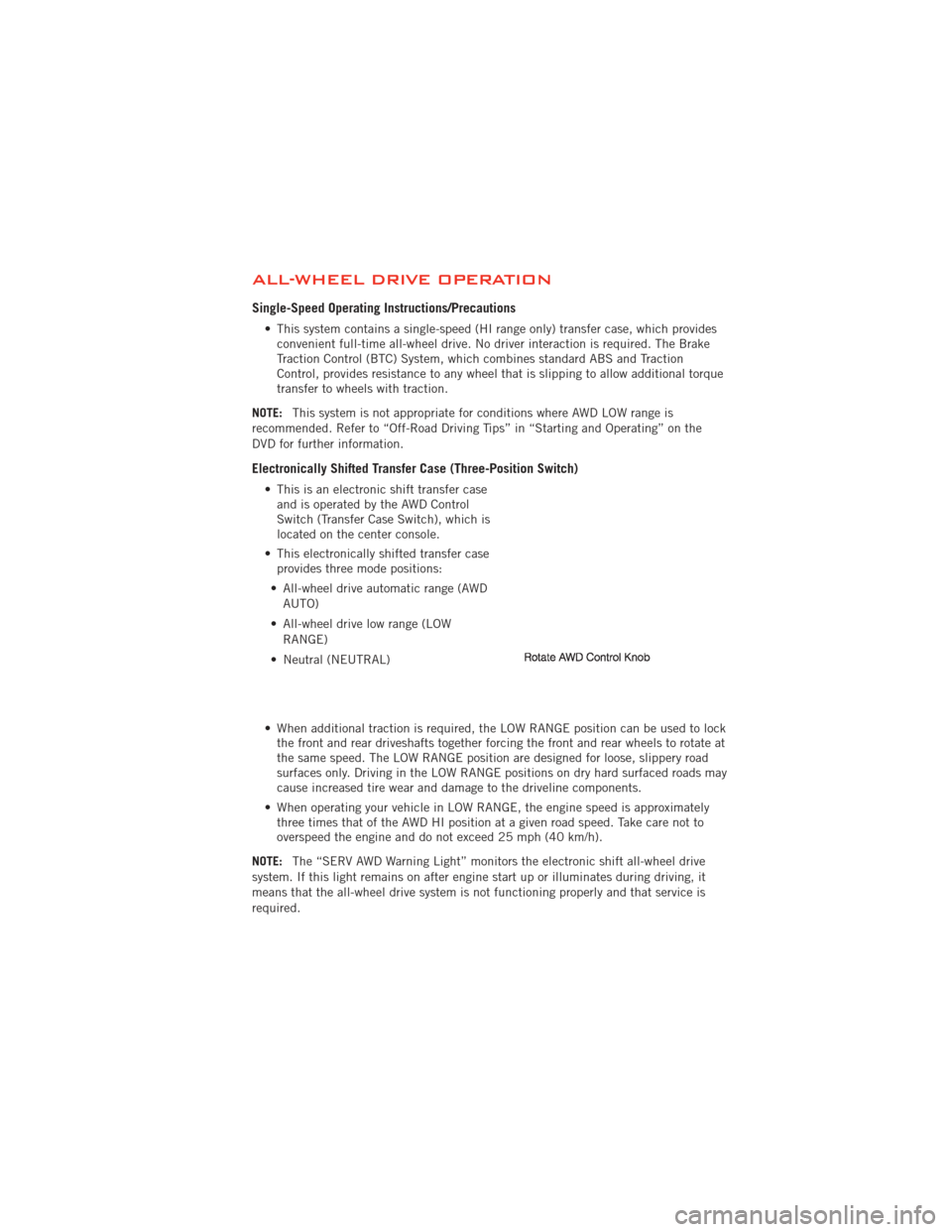
• This is an electronic shift transfer case and is operated by the AWD Control
Switch (Transfer Case Switch), which is
located on the center console.
• This electronically shifted transfer case provides three mode positions:
• All-wheel drive automatic range (AWD AUTO)
• All-wheel drive low range (LOW RANGE)
• Neutral (NEUTRAL)
• When additional traction is required, the LOW RANGE position can be used to lock the front and rear driveshafts together forcing the front and rear wheels to rotate at
the same speed. The LOW RANGE position are designed for loose, slippery road
surfaces only. Driving in the LOW RANGE positions on dry hard surfaced roads may
cause increased tire wear and damage to the driveline components.
• When operating your vehicle in LOW RANGE, the engine speed is approximately three times that of the AWD HI position at a given road speed. Take care not to
overspeed the engine and do not exceed 25 mph (40 km/h).
NOTE: The “SERV AWD Warning Light” monitors the electronic shift all-wheel drive
system. If this light remains on after engine start up or illuminates during driving, it
means that the all-wheel drive system is not functioning properly and that service is
required.
OFF-ROAD CAPABILITIES
83
Page 86 of 140
Shifting Procedures
AWD AUTO To LOW RANGE
NOTE: When shifting into or out of LOW RANGE some gear noise may be heard. This
noise is normal and is not detrimental to the vehicle or occupants.
• Shifting can be performed with the vehicle rolling 2 to 3 mph (3 to 5 km/h) orcompletely stopped. Use either of the following procedures:
Preferred Procedure • With the engine running, slow the vehicle to 2 to 3 mph (3 to 5 km/h).
• Shift the transmission into NEUTRAL.
• While still rolling, rotate the transfer case control switch to the desired position.
• After the desired position indicator light is ON (not flashing), shift the transmissionback into gear.
Alternate Procedure • Bring the vehicle to complete stop.
• With the ignition switch in the ON position and the engine either OFF or running,shift the transmission into NEUTRAL.
• Rotate the transfer case control switch to the desired position.
• After the desired position indicator light is ON (not flashing), shift the transmission back into gear.
NOTE:
• If Steps 1 or 2 of either the Preferred or Alternate Procedure are not satisfied prior to attempting the shift or if they no longer are being met while the shift attempt is in
process, the desired position indicator light will flash continuously while the original
position indicator light is ON, until all requirements have been met.
• The ignition switch must be in the ON position for a shift to take place and for the position indicator lights to be operable. If the ignition switch is not in the ON
position, then the shift will not take place and no position indicator lights will be on
or flashing.
WARNING!
• Always engage the parking brake when powering down the vehicle if the“SERV AWD Warning Light” is illuminated. Not engaging the parking brake
may allow the vehicle to roll which may cause personal injury.
• You or others could be injured if you leave the vehicle unattended with the transfer case in the NEUTRAL position without first fully engaging the
parking brake. The transfer case NEUTRAL position disengages both the front
and rear driveshafts from the powertrain and will allow the vehicle to move
regardless of the transmission position. The parking brake should always be
applied when the driver is not in the vehicle.
OFF-ROAD CAPABILITIES
84