wheel DODGE DURANGO 2012 3.G User Guide
[x] Cancel search | Manufacturer: DODGE, Model Year: 2012, Model line: DURANGO, Model: DODGE DURANGO 2012 3.GPages: 140, PDF Size: 4.3 MB
Page 3 of 140
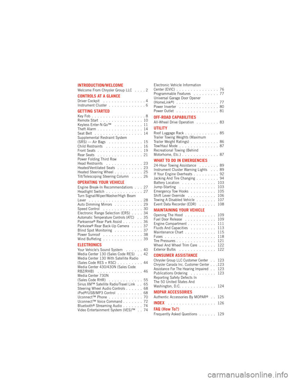
INTRODUCTION/WELCOMEWelcome From Chrysler Group LLC....2
CONTROLS AT A GLANCEDriver Cockpit...............4
Instrument Cluster .............6
GETTING STARTEDKeyFob...................8
Remote Start...............10
Keyless Enter-N-Go™ ..........11
Theft Alarm ................14
Seat Belt .................14
Supplemental Restraint System
(SRS) — Air Bags ............15
Child Restraints .............16
Front Seats ................19
Rear Seats ................21
Power Folding Third Row
Head Restraints .............23
Heated/Ventilated Seats .........23
Heated Steering Wheel ..........25
Tilt/Telescoping Steering Column ....26
OPERATING YOUR VEHICLEEngine Break-In Recommendations . . . 27
Headlight Switch.............27
Turn Signal/Wiper/Washer/High Beam
Lever ...................28
Auto Dimming Mirrors ..........29
Speed Control ..............30
Electronic Range Selection (ERS) ....34
Automatic Temperature Controls (ATC).. 35
Parksense®Rear Park Assist .......36
Parkview®Rear Back-Up Camera ....37
Blind Spot Monitoring ..........37
Power Sunroof ..............38
Wind Buffeting ..............39
ELECTRONICSYour Vehicle's Sound System ......40
Media Center 130 (Sales Code RES) . . 42
Media Center 130 With Satellite Radio
(Sales Code RES + RSC) .........44
Media Center 430/430N (Sales Code
RBZ/RHB) ................46
Media Center 730N
(Sales Code RHR) ............55
Sirius XM™ Satellite Radio/Travel Link.. 65
Steering Wheel Audio Controls ......68
iPod
®/USB/MP3 Control .........68
Uconnect™ Phone ............70
Uconnect™ Voice Command .......72
Bluetooth
®Streaming Audio .......74
Video Entertainment System (VES)™ . . 74 Electronic Vehicle Information
Center (EVIC)
...............76
Programmable Features .........77
Universal Garage Door Opener
(HomeLink
®) ...............77
Power Inverter ..............80
Power Outlet ...............81
OFF-ROAD CAPABILITIESAll-Wheel Drive Operation ........83
UTILITYRoof Luggage Rack............85
Trailer Towing Weights (Maximum
Trailer Weight Ratings) ..........86
Tow/Haul Mode ..............87
Recreational Towing (Behind
Motorhome, Etc.) .............87
WHAT TO DO IN EMERGENCIES24-Hour Towing Assistance .......89
Instrument Cluster Warning Lights . . . 89
If Your Engine Overheats .........92
Jacking And Tire Changing ........94
Battery Location ............ 103
Jump-Starting ............. 103
Emergency Tow Hooks ......... 105
Shift Lever Override .......... 106
Towing A Disabled Vehicle ....... 107
Event Data Recorder (EDR) ...... 108
MAINTAINING YOUR VEHICLEOpening The Hood........... 109
Fuel Door Release ........... 109
Engine Compartment .......... 111
Fluids And Capacities ......... 113
Maintenance Chart ........... 115
Fuses .................. 118
Tire Pressures .............. 121
Wheel And Wheel Trim Care ...... 122
Exterior Bulbs ............. 122
CONSUMER ASSISTANCEChrysler Group LLC Customer Center. . 123Chrysler Canada Inc. Customer Center...123Assistance For The Hearing Impaired. . 123
Publications Ordering ......... 123
Reporting Safety Defects In
The 50 United States And
Washington, D.C. ............ 124
MOPAR ACCESSORIESAuthentic Accessories By MOPAR®. . 125
INDEX................. 126
FAQ (How To?)Frequently Asked Questions ...... 129
TABLE OF CONTENTS
Page 7 of 140

A. Headlight Switch pg. 27
B. Turn Signal/Wiper/Washer/High BeamsLever (behind steering wheel) pg. 28
C. Instrument Cluster pg. 6
D. Electronic Vehicle Information Center (EVIC) Display pg. 76
E. Ignition Switch (behind steering wheel)
F. Audio System (touch-screen-radio shown) pg. 40
G. Climate Controls pg. 35 H. SWITCH PANEL
− Electronic Stability Control pg. 91
− Tow/Haul
− Heated Steering Wheel pg. 25
− Hazard Switch
− Power Inverter pg. 80
− ParkSense
®pg. 36
− Power Folding Third Row Head Restraints pg. 23
I. Transmission Gear Selector J. Power Outlet pg. 81
K. Speed Control pg. 30
L. EVIC Controls pg. 76
M. Fuel Door Release pg. 109
N. Parking Brake Release
O. Power Mirrors
P. Power Windows
Q. Power Door Locks
R. Driver's Memory Buttons pg. 19
CONTROLS AT A GLANCE
5
Page 18 of 140
WARNING!
• Relying on the air bags alone could lead to more severe injuries in a collision.The air bags work with your seat belt to restrain you properly. In some
collisions, the air bags won't deploy at all. Always wear your seat belts even
though you have air bags.
• Being too close to the steering wheel or instrument panel during Advanced Front Air Bag deployment could cause serious injury, including death. Air
bags need room to inflate. Sit back, comfortably extending your arms to
reach the steering wheel or instrument panel.
• Supplemental Side Air Bag Inflatable Curtains and Supplemental Seat-Mounted Side Air Bags need room to inflate. Do not lean against the
door or window. Sit upright in the center of the seat.
• Being too close to the Supplemental Side Air Bag Inflatable Curtain and/or Seat-Mounted Side Air Bag during deployment could cause you to be severely
injured or killed.
• Do not drive your vehicle after the air bags have deployed. If you are involved in another collision, the air bags will not be in place to protect you.
• After any collision, the vehicle should be taken to an authorized dealer immediately.
CHILD RESTRAINTS
• Children 12 years and under should ride properly buckled up in a rear seat, ifavailable. According to crash statistics, children are safer when properly restrained
in the rear seats rather than in the front.
• Every state in the United States and all Canadian provinces require that small children ride in proper restraint systems. This is the law, and you can be
prosecuted for ignoring it.
Installing The LATCH - Compatible Child Restraint System
• Your vehicle's second row passenger seats are equipped with the child restraintanchorage system called LATCH, which stands for Lower Anchors and Tether for
CHildren.
• Second and third row seating positions have lower anchorages that are capable of accommodating LATCH-compatible child seats having flexible, webbing-mounted
lower attachments.
• Child seats with fixed lower attachments must be installed in the outboard positions only.
• The vehicle's seat belt must be used for the center position.
• Never install LATCH-compatible child seats such that two seats share a common lower anchorage.
GETTING STARTED
16
Page 27 of 140
HEATED STEERING WHEEL
• The steering wheel contains a heatingelement that heats the steering wheel
to one temperature setting.
• The heated steering wheel switch is located on the center instrument panel
below the climate controls.
• Press the switch once to turn the heating element On. Press the switch a
second time to turn the heating
element Off.
• Once the heated steering wheel has been turned on, it will operate for approximately 58 to 70 minutes before automatically shutting off. The heated
steering wheel can shut off early or may not turn on when the steering wheel is
already warm.
GETTING STARTED
25
Page 28 of 140
TILT/TELESCOPING STEERING COLUMN
Manual - Tilt/Telescoping Steering Column
• The tilt/telescoping control handle islocated below the steering wheel at the
end of the steering column.
• Push the handle down to unlock the steering column.
• To tilt the steering column, move the steering wheel upward or downward as
desired. To lengthen or shorten the
steering column, pull the steering
wheel outward or push it inward as
desired.
• Pull up on the handle to lock the column firmly in place.
Power - Tilt/Telescoping Steering Column
• The power tilt/telescoping steering control is located below the turn
signal/wiper/washer/high beam lever on
the steering column.
• To tilt the steering column, move the power tilt/telescoping control up or
down as desired. To lengthen or
shorten the steering column, pull the
control toward you or push the control
away from you as desired.
WARNING!
• Do not adjust the steering wheel while driving. The tilt/telescopingadjustment must be locked while driving. Adjusting the steering wheel while
driving or driving without the tilt/telescoping adjustment locked could cause
the driver to lose control of the vehicle. Failure to follow this warning may
result in you and others being severely injured or killed.
• Moving the steering column while the vehicle is moving is dangerous. Without a stable steering column, you could lose control of the vehicle and
have a collision. Adjust the column only while the vehicle is stopped.
GETTING STARTED
26
Page 29 of 140
ENGINE BREAK-IN RECOMMENDATIONS
• A long break-in period is not required for the engine and drivetrain (transmissionand axle) in your vehicle.
• Drive moderately during the first 300 miles (500 km). After the initial 60 miles (100 km), speeds up to 50 or 55 mph (80 or 90 km/h) are desirable.
• While cruising, brief full-throttle acceleration within the limits of local traffic laws contributes to a good break-in. Wide-open throttle acceleration in low gear can be
detrimental and should be avoided.
• The engine oil installed in the engine at the factory is a high-quality energy conserving type lubricant. Oil changes should be consistent with anticipated
climate conditions under which vehicle operations will occur. For the
recommended viscosity and quality grades, refer to “Maintaining Your Vehicle”.
NOTE: A new engine may consume some oil during its first few thousand miles
(kilometers) of operation. This should be considered a normal part of the break-in and
not interpreted as an indication of difficulty.
CAUTION!
Never use Non-Detergent Oil or Straight Mineral Oil in the engine or damage
may result.
HEADLIGHT SWITCH
Automatic Headlights/Parking
Lights/Headlights
• Rotate the headlight switch, located on the instrument panel to the left of the
steering wheel, to the first detent for
parking lights
andtothe
second detent for headlights.
• With the parking lights or low beam headlights on, push the headlight
switch once for fog lights.
• Rotate the headlight switch to “AUTO” for AUTO headlights.
• When set to AUTO, the system automatically turns the headlights on
or off based on ambient light levels.
SmartBeams™
• This system automatically controls the use of the headlight high beams. Refer toProgrammable Features in Electronics for further details.
OPERATING YOUR VEHICLE
27
Page 32 of 140
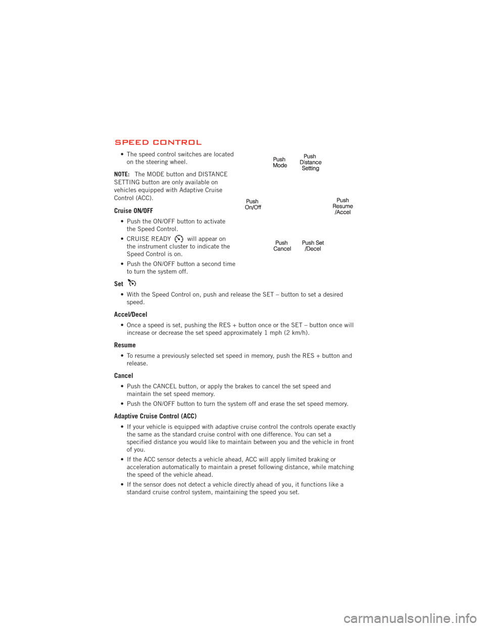
SPEED CONTROL
• The speed control switches are locatedon the steering wheel.
NOTE: The MODE button and DISTANCE
SETTING button are only available on
vehicles equipped with Adaptive Cruise
Control (ACC).
Cruise ON/OFF
• Push the ON/OFF button to activate the Speed Control.
• CRUISE READY
will appear on
the instrument cluster to indicate the
Speed Control is on.
• Push the ON/OFF button a second time to turn the system off.
Set
• With the Speed Control on, push and release the SET – button to set a desiredspeed.
Accel/Decel
• Once a speed is set, pushing the RES + button once or the SET – button once willincrease or decrease the set speed approximately 1 mph (2 km/h).
Resume
• To resume a previously selected set speed in memory, push the RES + button andrelease.
Cancel
• Push the CANCEL button, or apply the brakes to cancel the set speed andmaintain the set speed memory.
• Push the ON/OFF button to turn the system off and erase the set speed memory.
Adaptive Cruise Control (ACC)
• If your vehicle is equipped with adaptive cruise control the controls operate exactly the same as the standard cruise control with one difference. You can set a
specified distance you would like to maintain between you and the vehicle in front
of you.
• If the ACC sensor detects a vehicle ahead, ACC will apply limited braking or acceleration automatically to maintain a preset following distance, while matching
the speed of the vehicle ahead.
• If the sensor does not detect a vehicle directly ahead of you, it functions like a standard cruise control system, maintaining the speed you set.
OPERATING YOUR VEHICLE
30
Page 70 of 140
STEERING WHEEL AUDIO CONTROLS
• The steering wheel audio controls arelocated on the rear surface of the
steering wheel.
Right Switch
• Press the switch up or down toincrease or decrease the volume.
• Press the button in the center to change modes
AM/FM/DISC/SAT/HDD/AUX.
Left Switch
• Press the switch up or down to search for the next listenable station or select thenext or previous CD or HDD track.
• Press the button in the center to select the next preset station (radio) or to change CDs if equipped with a CD Changer.
iPod®/USB/MP3 CONTROL
• There are many ways to play music from iPod®/MP3 players or USB devices
through your vehicle's sound system.
• The remote USB port, located within the center console, allows you to plug an iPod
®into the vehicle's sound system.
NOTE: If equipped with the Media Center
730N (RHR), the USB port on the
faceplate allows the same functions as the
remote USB port.
• Non-Touch-Screen Radios: To hearaudio from devices connected to the
USB port, press the “AUX” button on
the radio faceplate
• Touch-Screen Radios: To hear audio from devices connected to the USB
port, press the “MEDIA” hard-key, then
touch the “AUX” or “iPod
®” soft-key.
ELECTRONICS
68
Page 74 of 140
Mute (Or Unmute) Microphone During Call
• During a call, press the “Voice Command” button.
• (After the BEEP), say “mute” (or “mute off”).
Transfer Ongoing Call Between Handset And Vehicle
• During a call, press the “Voice Command” button.
• (After the BEEP), say “transfer call”.
Changing The Volume
• Start a dialogue by pressing the “Phone” button, then adjust the volume
during a normal call.
• Use the radio ON/OFF VOLUME rotary knob to adjust the volume to a comfortable level while the Uconnect™ system is speaking. Please note the volume setting for
Uconnect™ is different than the audio system.
WARNING!
• Any voice commanded system should be used only in safe driving conditionsfollowing local laws and phone use. All attention should be kept on the
roadway ahead. Failure to do so may result in a collision causing you and
others to be severely injured or killed.
• In an emergency, to use Uconnect™ Phone, your mobile phone must be: • turned on,
• paired to Uconnect™ Phone,
• and have network coverage.
Uconnect™ VOICE COMMAND
• The Uconnect™ Voice Command system allows you to control your AM, FM radio,satellite radio, disc player, HDD, Uconnect™ Phone, a memo recorder, and
supported portable media devices.
• When you press the “Voice Command” button
located on the radio
faceplate or steering wheel, you will hear a beep. The beep is your signal to give a
command. If you do not say a command within a few seconds, the system will
present you with a list of options. If you ever wish to interrupt the system while it
lists options, press the “Voice Command” button
, listen for the BEEP, and
say your command.
Voice Command Operation
• Start a dialogue by pressing the “Voice Command” button, you will
hear a beep. The beep is your signal to
give a command. Below are a list of
voice commands for each of the
different modes.
ELECTRONICS
72
Page 78 of 140
ELECTRONIC VEHICLE INFORMATION CENTER
(EVIC)
• The EVIC features a driver interactivedisplay that is located in the
instrument cluster. Pressing the
controls on the left side of the steering
wheel allows the driver to select
vehicle information and Personal
Settings. For additional information,
refer to Programmable Features in this
guide.
• Press and release the UP
button
to scroll upward through the main
menus (Fuel Economy, Vehicle Speed,
Trip Info, Tire PSI, Vehicle Info,
Messages, Units, System Setup) and
sub menus.
• Press and release the DOWN
button to scroll downward through the main menus and sub menus.
• Press and release the SELECT
button for access to main menus, sub menus or
to select a personal setting in the setup menu.
• Press the BACK button to scroll back to a previous menu or sub menu.
NOTE: Refer to the Driver Cockpit image in Controls At A Glance to see EVIC Display
and EVIC Controls location.
Compass Calibration
• This compass is self-calibrating, which eliminates the need to set the compass manually. When the vehicle is new, the compass may appear erratic and the EVIC
will display “CAL” until the compass is calibrated.
• You may also calibrate the compass manually by selecting Setup (Customer- Programmable Features) in the EVIC, then select Compass Variance and then enter
the correct variance. Next, select Calibrate Compass in the Setup menu to start the
calibration process. The “CAL” indicator will be displayed in the EVIC. Complete
one or more 360 degree turns (in an area free from large metal or metallic objects)
until the “CAL” message displayed in the EVIC turns off. The compass will now
function normally.
ECO
• The ECO message will appear in your EVIC display whenever you are driving in afuel efficient manner.
• This feature allows you to monitor when you are driving in a fuel efficient manner, and it can be used to modify driving habits in order to increase fuel economy.
ELECTRONICS
76